David Park ordered 400 pieces of QSFP28-to-4×SFP28 breakout DACs for a new leaf switch deployment in Seoul. The cables looked good and seated properly. However, the team soon discovered that only half of the switch ports actually supported breakout mode. The remaining ports could only run at 100G. With 200 cables left unused in the corner, the server cutover was delayed by a full week and the project went $30,000 over budget.
This is a classic example of the hidden challenges in QSFP28 breakout cable deployments. The cable itself is only one piece of the puzzle — switch port support, distance, power budget, and signaling compatibility all play critical roles in successful operation.
This guide will help you select the right breakout cable for your 100G-to-25G architecture, verify switch compatibility, and avoid the common mistakes that delay deployments.
Need help selecting breakout cables? Explore Ascent Optics’ QSFP28 connectivity solutions or contact our engineers for a free compatibility review.
What Is a QSFP28 Breakout Cable?
A QSFP28 breakout cable splits a single 100G QSFP28 port into four separate 25G connections. This architecture divides the 100G signal into four independent 25G lanes, allowing one leaf switch port to connect to four 25G server ports.
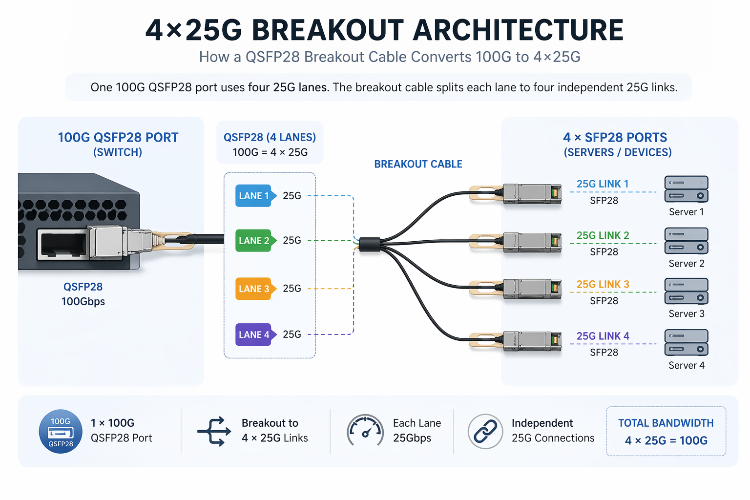
How Breakout Architecture Works (4×25G)
A 100G rate of transmission is transmitted via four 25G NRZ lanes in the QSFP28 modules. In a breakout cable, these four lanes are physically allocated to four individual SFP28 connectors. Each SFP28 is fed from one lane of 25G to a server NIC or another switch port.
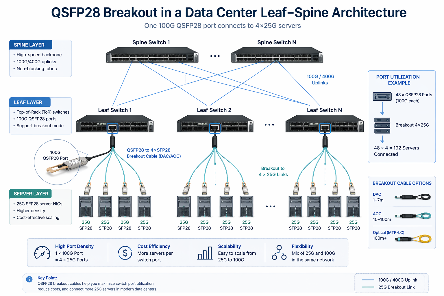
This design has become the standard for modern data centers because it maximizes port utilization. A single 48-port QSFP28 leaf switch that fully supports breakout can connect up to 192 × 25G servers.
QSFP28 Breakout vs Standard QSFP28 Transceivers
Breakout cables are not transceivers. They provide a direct-attach copper or optical assembly between one QSFP28 port and four SFP28 ports for short-reach links. For longer distances or structured cabling, the alternative is to use separate QSFP28 and SFP28 transceivers over a fiber plant.
For a broader introduction to 100G connectivity, see our QSFP28 transceiver guide.
QSFP28 Breakout Cable Types Explained
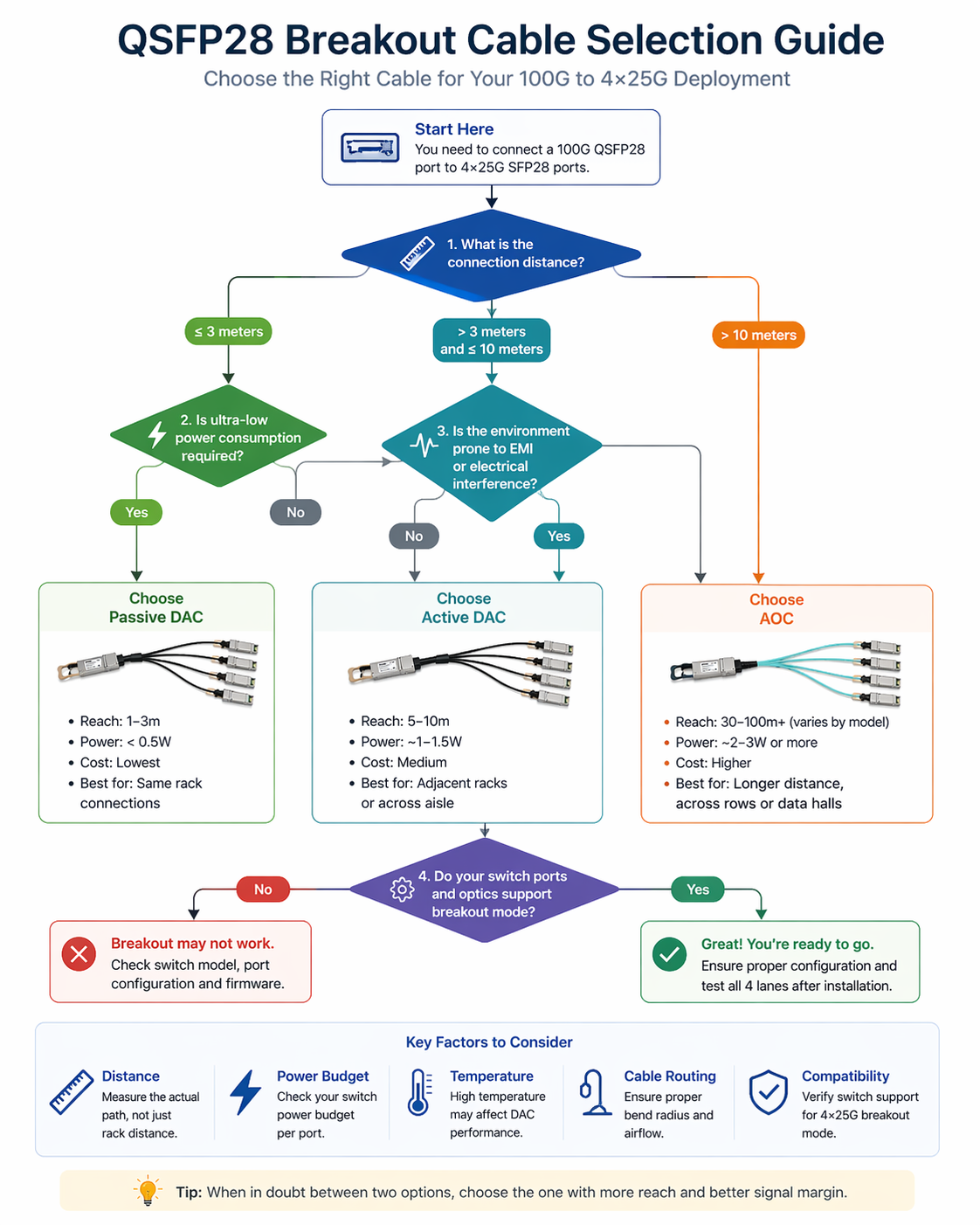
Not all breakout cables are built the same. The right type depends on distance, power budget, and physical routing constraints.
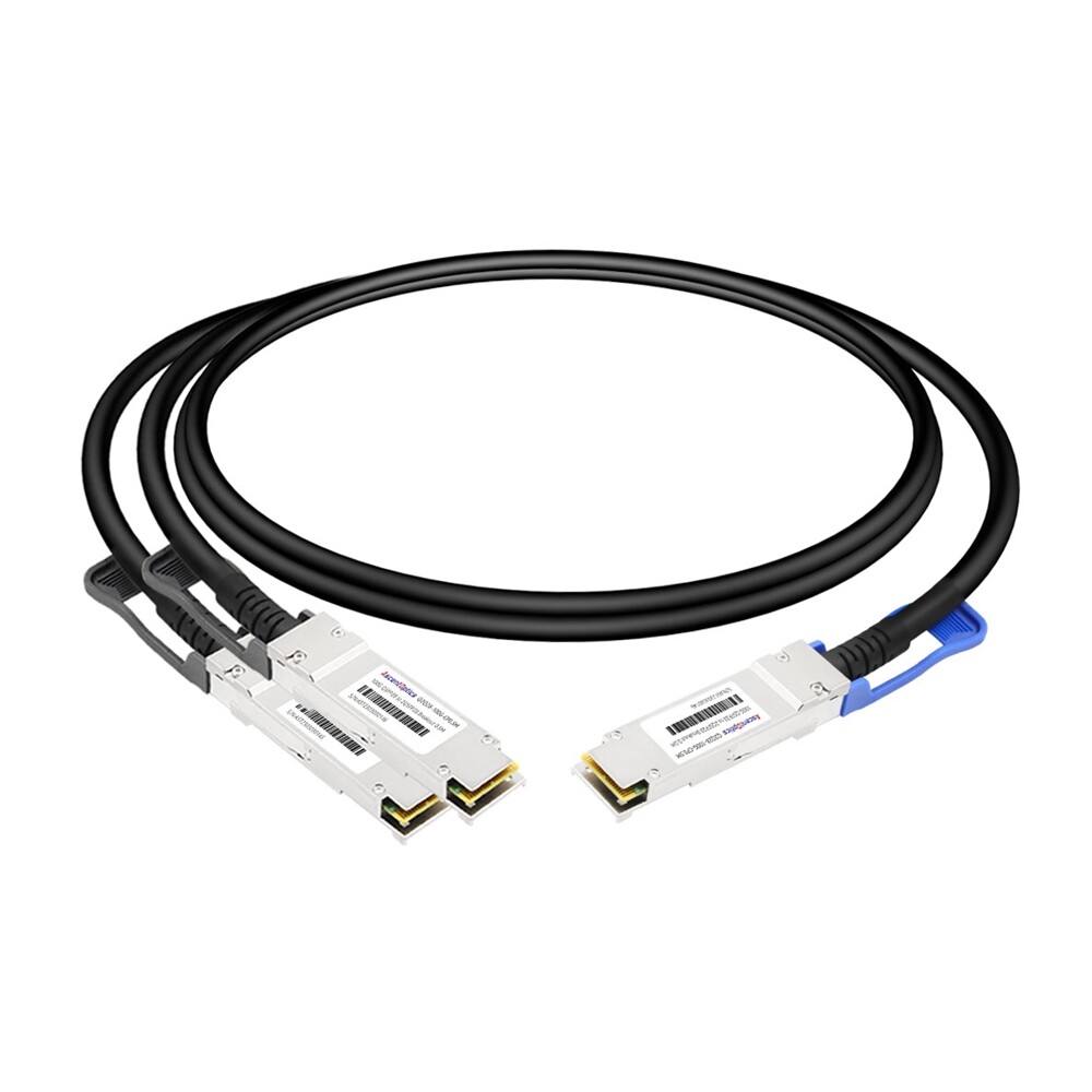
Passive Direct Attach Copper (DAC)
Passive DAC cables use copper traces without signal amplification. They are the lowest-power and most cost-effective option. Typical lengths range from 1 to 3 meters (some manufacturers offer up to 5 meters). Passive DACs are ideal for servers located in the same rack as the leaf switch or in adjacent racks.
Active Direct Attach Copper (Active DAC)
Active DACs include electronic signal conditioning inside the QSFP28 connector, allowing reaches of 5 to 10 meters. They consume slightly more power than passive DACs but remain significantly cheaper than AOCs. Active DACs work the best for racks across an aisle or next to racks where passive copper fails to maintain signal integrity.
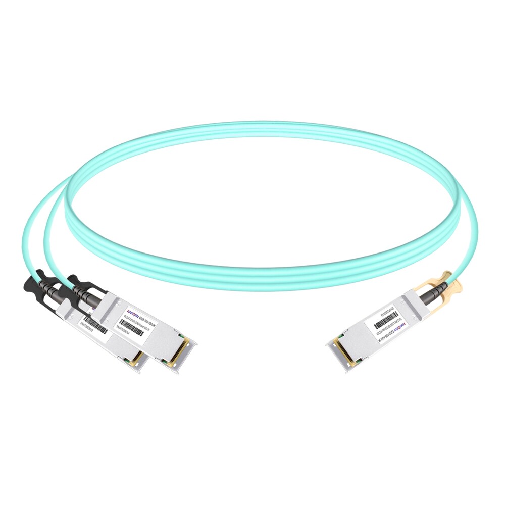
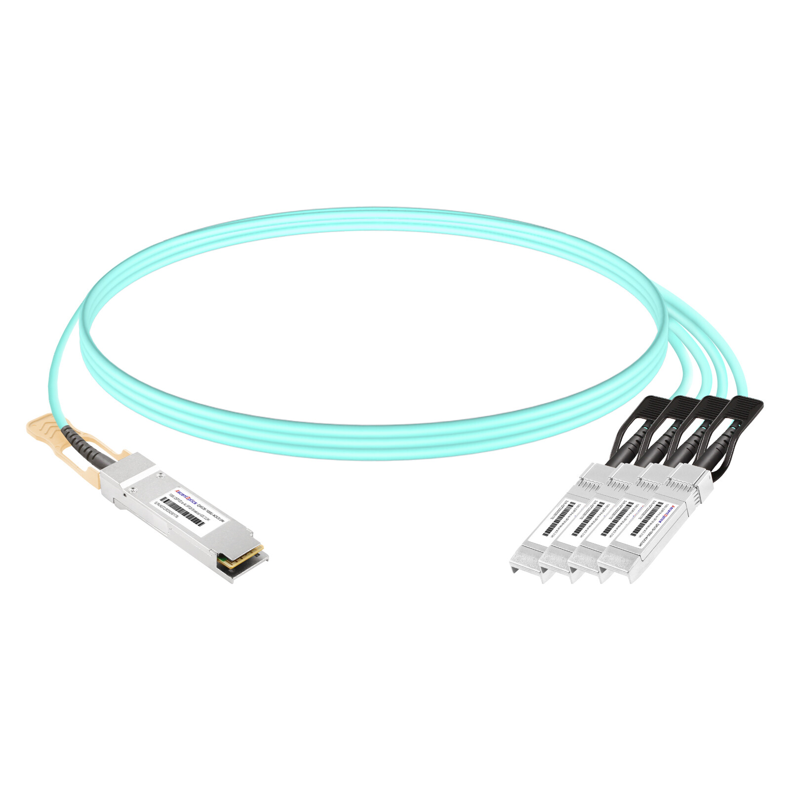
Active Optical Cable (AOC)
AOC breakout cables use multimode fiber with integrated optical transceivers at both ends. They can reach 30 to 100 meters depending on fiber grade and design. Although more expensive and power-intensive than DACs, AOCs solve distance and electromagnetic interference issues that copper cannot handle.
AOCs are commonly used when servers are more than 10 meters from the leaf switch or when copper becomes unreliable due to EMI.
Breakout Optical Fiber Cables (MTP to LC)
In a structured cabling situation, you might install a QSFP28 SR4 transceiver on the switch side and break this out into four SFP28 SR transceivers using a MTP-to-4×LC breakout harness on the server side. This allows one to use traditional optical transceivers instead of direct-attach cables and is the preferable mode of action when already having fixed structural cabling in place.
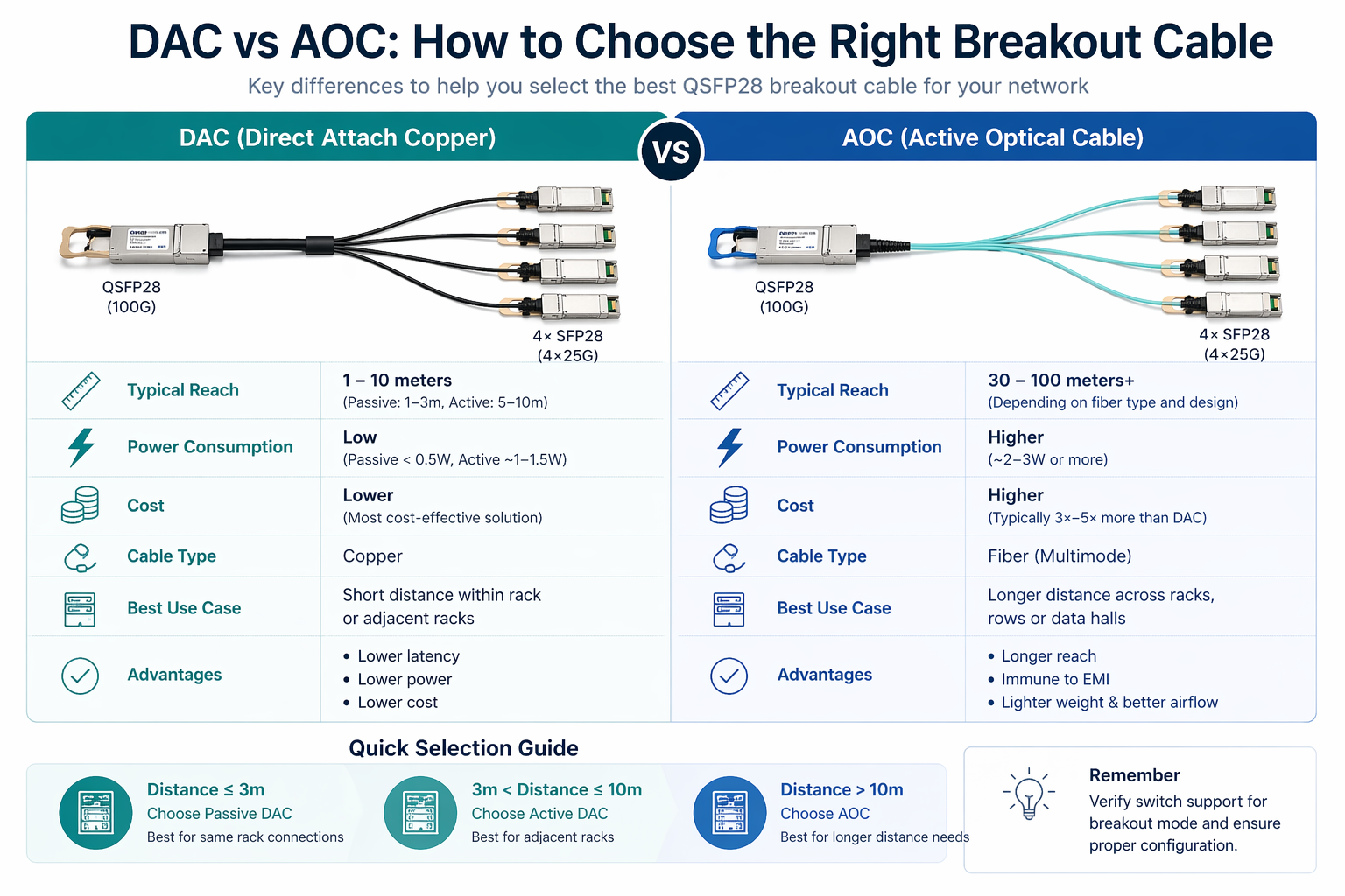
DAC vs AOC: How to Choose
The DAC versus AOC decision is usually the first technical choice in a breakout deployment.
Distance Comparison
| Cable Type |
Typical Reach |
| Passive DAC |
1–3 meters |
| Active DAC |
5–10 meters |
| AOC |
30–100 meters |
Power and Thermal Comparison
Passive DACs consume less than 0.5 W per end. Active DACs typically draw 1.5–2.5 W, while AOCs range from 2–4 W. The lower power of DACs makes them popular in power-constrained designs.
Cost Comparison
Passive DACs are the cheapest per link. Active DACs are typically 20–40% more expensive than passive versions. For the same breakout configuration, AOCs can be 3× to 5× more expensive than passive DACs.
When to Choose DAC
Choose a DAC when:
- •Servers are within 3 meters (passive) or 10 meters (active)
- •Power and thermal budgets are tight
- •Cost per link is a primary concern
- •Electromagnetic interference is not an issue
When to Choose AOC
Choose an AOC when:
- •Servers are more than 10 meters from the switch
- •You need a lightweight, flexible cable for dense cable management
- •Electromagnetic interference is present
- •Permanent structured fiber cabling is not yet installed
Jennifer Tan was managing a colocation facility in Singapore. Her leaf switches had to reach servers across a 15m aisle. She first tried using active DACs due to cost saving, which led to two out of every four lanes of three cables showing intermittent errors at 8 meters. She changed to 20m AOCs and observed instant link stabilization. Although the AOCs are more expensive initially than DACs, they saved her troubleshooting time and kept her from having to work on a cable re-routing project.
DAC vs AOC Quick Reference
| Factor |
Passive DAC
|
Active DAC |
AOC
|
| Distance |
≤3 m
|
≤10 m |
≤100 m
|
| Power draw |
<0.5W
|
1.5W–2.5W |
2W–4W
|
| Cost |
Lowest
|
Low |
Higher
|
| Weight |
Heavier
|
Heavier |
Lighter
|
| EMI sensitivity |
Moderate
|
Moderate |
None
|
| Best for |
Same rack
|
Nearby racks |
Longer runs
|
Connector Configurations and Polarity
Understanding connector layout prevents polarity mismatches that cause link failures.
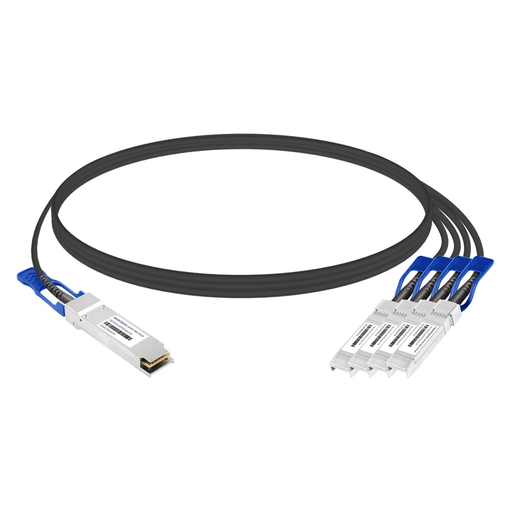
QSFP28-to-4×SFP28 Breakout
There is a standard breakout configuration, where one QSFP28 connector is on the switch side and four individual SFP28 connectors are present on the server side. Each SFP28 handles a single 25G lane.
QSFP28-to-4×SFP28 Hybrid Breakout
Some custom rollouts use hybrid cables mixing different connector types, which includes QSFP28-to-4×SFP28 having different latch orientations or pull-tab style. Such unions of cables are more or less cosmetic or mechanical changes rather than real electrical ones, but they are important in dense cable management areas.
Fiber Polarity and Strand Mapping (AOC)
The four optical fibers within breakout links must map to the four Tx/Rx pairs across each end. In most cases the average certified AOC comes from the factory with the correct polarity (Method B or Method C, depending on the application). If you are making MTP-to-LC breakout cables from scratch instead of using AOCs, the polarity of the link will have to be considered as part of the design.
Switch Breakout Compatibility by Vendor
This is where most breakout deployments fail. Not every QSFP28 port supports breakout mode.
Cisco Nexus Breakout Support
On many switches of the Cisco Nexus 9300 series, efforts are made to retrofit the breakout facility for specific port groups. For instance, on just a few magistral portions can 4×25G breakout be implemented, while the rest remains strictly 100G native. The actual mapping of the ports involves the SKU and regulations supervised.
Arista 7000 Series Breakout Ports
Arista EOS provides flexible per-port speed configuration. Most QSFP28 ports on 7060X4 and 7280R3 series switches support 4×25G breakout. Always verify the hardware datasheet for the exact model.
Juniper QFX Breakout Configuration
Juniper QFX5120 switches support 4×25G breakout on most QSFP28 ports, but Junos OS usually requires explicit channelization configuration. The QFX10002 series offers more comprehensive breakout support but may need specific port group mapping.
NVIDIA Spectrum Breakout Modes
The NVIDIA SN4600C and SN4700 switches lend themselves to 4x25G breakout on most ports. The configuration of breakouts is supported inside Onyx and Cumulus Linux in cases where the CLI configuration might differ. The SN5600 ports supporting OSFP ports will achieve a QSFP28 breakout with subsequent adapters.
For a detailed vendor-by-vendor breakdown, see our QSFP28 compatible switches guide.
Why Not All Ports Support Breakout
The ASIC port is placed in breakout mode where four independent 25G SerDes lanes are exposed from a single physical QSFP28 cage. This feature is only supported on specific ports from some ASICs due to electrical lane mapping, while others support it in hardware but require an exclusive software license or firmware version.
Breakout vs Discrete Optics: When to Use Each
Breakout cables are not always the best solution. Sometimes discrete transceivers make more sense.
Breakout Cables for Leaf-to-Server
Breakout cables excel in leaf-to-server connections where distances are short and fiber count needs to be minimized. A single QSFP28 port can serve four servers, reducing the number of switch ports and optics to manage.
Discrete SFP28 Transceivers for Longer Runs
If the rack to rack distance exceeds 100 meters or you need to traverse structured cabling plant with patch panels, I would recommend using discrete optics. The switch end might have a QSFP28 CWDM4 or LR4, the plant might employ fiber patch cables with SFP28 modules LR or ER at the end of servers.
Cost and Management Tradeoffs
Breakout cables reduce part count and simplify installation. Pluggable optics offer greater flexibility for reconfiguration and longer reach. In most data centers, leaf-to-server links use breakout cables, while leaf-to-spine uplinks use standard 100G transceivers.
Common QSFP28 Breakout Cable Pitfalls
Even experienced engineers make these mistakes. Here is how to avoid them.
The QSFP+ vs QSFP28 Breakout Confusion
QSFP+ breakout cables split 40G into four 10G SFP+ links. QSFP28 breakout cables split 100G into four 25G SFP28 links. The physical connectors look similar, but the signaling is completely different.
Marcus Rodriguez spearheaded a network upgrade in Mexico. His team was on the process of migrating from 40G to 100G leaf switches. They had QSFP+-to-4xSFP+ breakout cables in stock that they tried with the new QSFP28 ports just as a precaution. The cables seated perfectly, but there was no link on the 25G server NICs. After an all-day marathon of troubleshooting firmware and port settings, someone who should have known beforehand paid attention to the cable labeling: it showed “QSFP+” and not “QSFP28.” In turn, the 10G signaling coming from the old cables was not able to engage with the 25G ports, and they had to rush-order in the vicinity of 300 new breakout cables.
Ordering Breakout for Non-Breakout Ports
Always verify that the specific switch ports you plan to use support breakout mode. Check the hardware datasheet, not just the general product family brochure.
Wrong Cable Length and Bend Radius
Active DACs tend to have worse signal performance when corners are encountered on tight bends in dense cable management. In contrast to DACs, active optical cables (AOCs) have a lesser degree of flexibility because of the glass fibers of which they are comprised.
Ignoring FEC on Breakout Links
Breakout links are typically carried on setups having switches from various makers, or run between switches and server NICs. If one side uses FC-FEC and the other requires RS-FEC, there is a likelihood that on the individual 25G lanes, the flap and CRC errors would also occur.
Mismatched Fiber Polarity in AOCs
If you are building custom MTP-to-LC breakout harnesses instead of buying pre-terminated AOCs, verify fiber polarity before installation. A polarity mismatch can leave two or four lanes dark while the others work.
Need help validating your breakout design? Contact our optical networking experts for a pre-deployment review.
Step-by-Step Breakout Deployment Checklist
Follow this checklist to ensure your breakout deployment succeeds the first time.
Step 1: Confirm Switch Port Breakout Support
Determine the accurate switch model and ports that you are planning to use. Check the breakout support in the hardware datasheet and vendor compatibility matrix.
Step 2: Measure Distance and Choose DAC or AOC
path the cable really follows and not straight-line distance. You have to take into account cable-management slack. Go with passive DAC over a length of up to 3 m, active DAC for lengths from 3 m to 10 m, and AOC for greater lengths.
Step 3: Verify Server NIC Compatibility
Confirm that the server NICs are 25G SFP28, not 10G SFP+. Also verify that the NICs support the same FEC mode as the switch.
Step 4: Configure Breakout Mode on the Switch
Use the correct CLI commands for your platform. Cisco NX-OS, Arista EOS, Juniper Junos, and NVIDIA Onyx/Cumulus all use different syntax for breakout channelization.
Step 5: Test and Validate All Four Lanes
After installation, test every lane independently. A breakout cable can show three working lanes and one dark lane due to a bad connector, polarity issue, or FEC mismatch.
Conclusion
A QSFP28breakout cable is more than a copper or fiber assembly. It is a critical piece of a 100G-to-25G architecture that must match your switch ports, server distance, power budget, and signaling requirements.
Key takeaways:
- •Match cable type to distance. Passive DAC for short runs, active DAC for medium runs, AOC for longer runs.
- •Verify breakout support on every port. Not all QSFP28 ports support 4×25G breakout.
- •Do not confuse QSFP+ and QSFP28 breakout cables. The signaling rates are different and they are not interchangeable.
- •Match FEC settings across switches and server NICs.
- •Test all four lanes independently. One bad connector or polarity mismatch can leave a single lane dark.
Ready to deploy your breakout architecture? Explore Ascent Optics’ QSFP28 connectivity solutions and request a quote for your project. For broader 100G guidance, read our QSFP28 transceiver guide. And if you are planning a migration from 40G, see our 40G to 100G migration guide.
Frequently Asked Questions
Q1 What is a QSFP28 breakout cable?
A QSFP28 breakout cable is a direct-attach or active optical cable used to break a single 100G QSFP28 port into four 25G SFP28 ports, allowing a single switch port to connect to four servers or endpoints.
Q2. What is the difference between QSFP+ and QSFP28 breakout cables?
QSFP+ breakout cables split 40G into four 10G SFP+ links, while QSFP28 breakout cables split 100G into four 25G SFP28 links. They cannot be substituted because the lane signaling rates are different.
Q3. How far can QSFP28 breakout DAC cables reach?
Passive DACs are usually of a length 1 meter to 3 meters. Active DACs can usually reach a length of 5 to 10 meters. For any distances exceeding 10 meters, you will need an AOC breakout cable.
Q4. Do all QSFP28 switch ports support the breakout mode?
No not all of them do. It seldom depends on the switch ASIC, port group mapping, or even firmware/licensing. So make sure to check breakout support for the exact ports you are considering using.
Q5. When should I consider using AOC rather than DAC for breakout?
AOC can be used when server distance is more than 10 meters, when you need light cables for dense cabling solutions, or when electromagnetic interference makes copper unreliable.
Q6. Can I use breakout cables and standard 100G transceivers together on the same switch?
Yes, as long as the ports support the modes required. Some chassis are capable of accommodating mixed breakout and native 100G ports.
Q7. What FEC mode do I use for QSFP28 breakout links?
Most 25G breakout links use either FC-FEC or RS-FEC. Set the FEC option in both the switch and the server NIC to either FC-FEC or RS-FEC. Mismatched FEC settings often lead to lane flapping.
IEEE 802.3bm standards
Cisco Nexus Breakout Configuration Guide
Post Views: 1,461