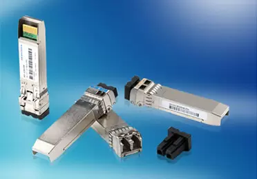
Upgrading a data center from 100G to 400G used to mean more than buying faster optics. Engineers had to check switch ASIC lane rates, module thermal envelopes, fiber type, connector layout, and the migration path from existing 100G links. QSFP112 simplifies part of that transition by delivering 400G-class bandwidth in the familiar QSFP mechanical envelope, but it is not a drop-in upgrade for every QSFP28 environment.
For network infrastructure teams, the value of QSFP112 is practical: four high-speed electrical lanes, a compact front-panel footprint, and strong alignment with modern 400G Ethernet and InfiniBand designs. The key is understanding where the compatibility ends. Physical similarity does not guarantee electrical compatibility, firmware support, thermal readiness, or breakout support.
What Is a QSFP112 Transceiver?
Technical Foundation
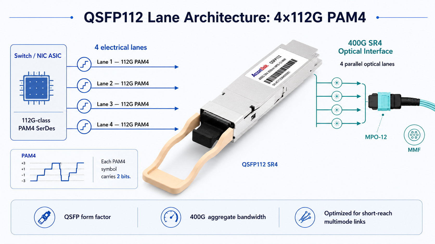
A QSFP112 transceiver is a 400G-class optical transceiver module built around a four-lane electrical interface. Each host electrical lane is in the 100G/112G PAM4 SerDes class. The “112” in QSFP112 refers to the per-lane electrical signaling generation, not the user payload rate. In practical Ethernet deployments, this supports 400GbE interfaces such as 400GBASE-SR4, DR4, FR4, and LR4 variants.
The form factor is based on the established QSFP mechanical family. A QSFP112 module uses the same general module width and height as QSFP28/QSFP56, which helps vendors preserve front-panel density. However, the connector, cage, host PCB, and ASIC must be designed for 112G-class PAM4 operation. A legacy QSFP28 cage may look similar, but that does not mean it is validated for QSFP112 signal integrity or thermal requirements.
The electrical interface relies on PAM4 signaling. PAM4 encodes two bits per symbol, increasing lane throughput compared with NRZ at a similar symbol rate. This reduces the number of host lanes needed for 400G compared with earlier eight-lane 400G implementations, but it also raises the requirements for channel loss, equalization, host firmware, and module diagnostics.
How QSFP112 Differs from QSFP28
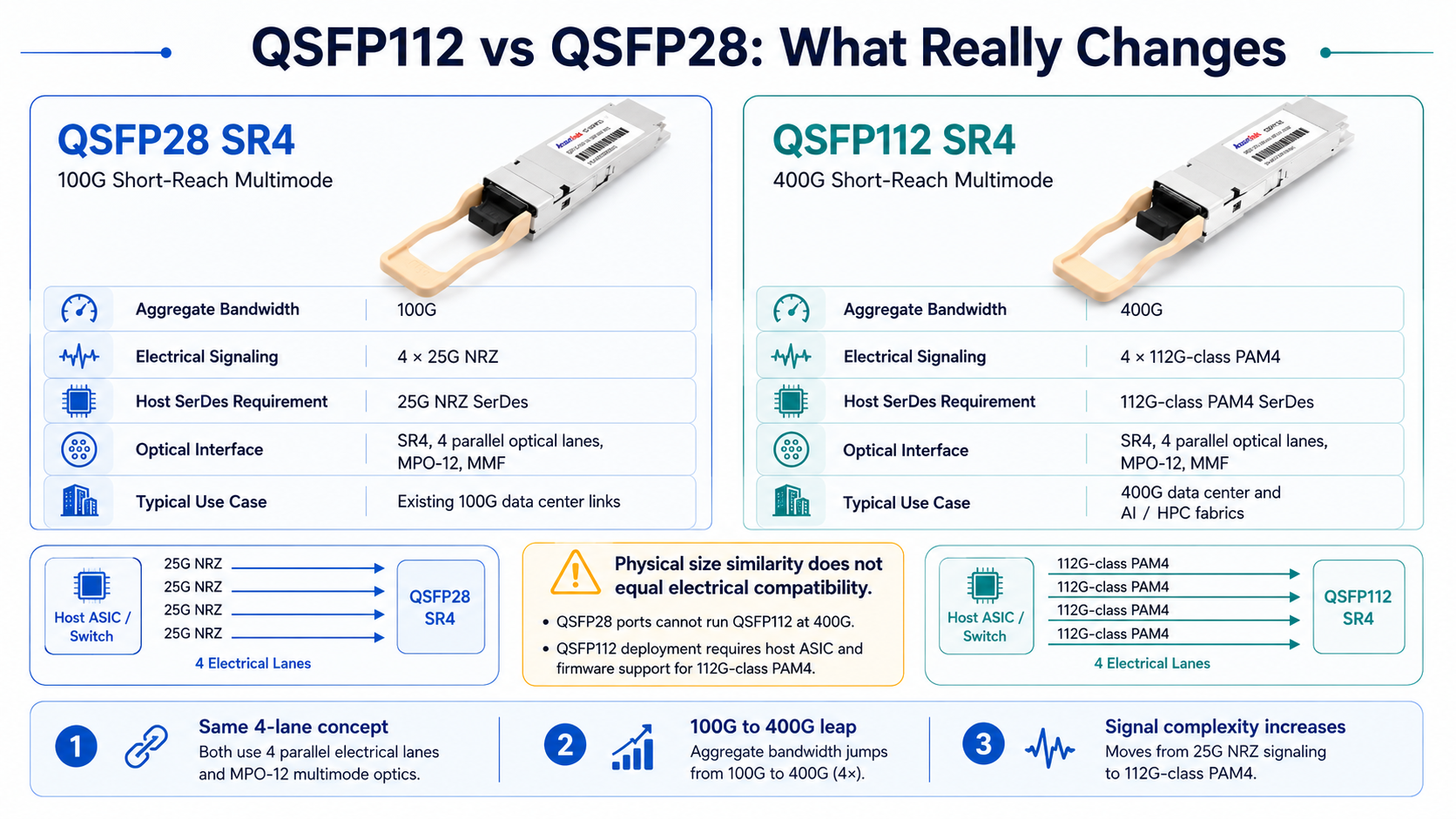
The jump from QSFP28 to QSFP112 is not just a bandwidth increase. QSFP28 100G modules typically use four 25G NRZ electrical lanes. QSFP112 400G modules use four high-speed PAM4 electrical lanes in the 100G/112G class. The lane count stays at four, but the electrical signaling, host SerDes capability, and signal-integrity budget are completely different.
This distinction matters for procurement. A QSFP112-capable port may accept older QSFP28 or QSFP56 modules if the switch vendor supports the required lower-speed port modes. A QSFP28-only port cannot run a QSFP112 module at 400G because it lacks the 112G-class PAM4 electrical interface. Always treat QSFP112 compatibility as a host-port and firmware question, not only a cage-size question.
For a deeper look at how QSFP form factors have evolved, our guide to QSFP28 transceivers covers the 100G standard that QSFP112 is built to replace.
QSFP112 vs QSFP28: Should You Upgrade?
When QSFP28 Still Makes Sense
Not every network needs an immediate 400G upgrade. QSFP28 remains cost-effective for stable 100G environments, including enterprise campus cores, regional interconnects, and access-layer uplinks where bandwidth demand is predictable.
QSFP28 also makes sense when the switching platform does not support 112G PAM4 SerDes. If the hardware refresh cycle is still 12 to 18 months away, it may be more economical to continue using QSFP28 optics and plan a coordinated upgrade of switches, optics, cabling, and monitoring tools later. QSFP28 optics have mature supply chains, broad vendor support, and competitive pricing.
When to Migrate to QSFP112
QSFP112 becomes compelling when the network needs higher bandwidth per front-panel port. AI and machine-learning clusters are the most visible examples because GPU training workloads generate heavy east-west traffic and frequent all-to-all communication. A 100G port can become a bottleneck in rail-optimized and fat-tree designs, while 400G provides more headroom per server or switch uplink.
QSFP112 is also attractive for spine-layer upgrades and high-density 400G Ethernet designs. Because it uses four host electrical lanes rather than eight, it can reduce host-side complexity compared with some QSFP-DD 400G implementations. Power comparisons should still be made by module type and vendor datasheet: a QSFP112 DR4 may be lower power than a comparable QSFP-DD DR4, but the advantage is not universal across every reach and silicon generation.
Need help deciding between 400G form factors? See how QSFP112 compares to QSFP-DD across power, compatibility, and forward scalability.
Migration Considerations
When Marcus Chen, a senior network engineer at a mid-size cloud provider in Singapore, was tasked with upgrading 32 spine ports from 100G to 400G, his first question was whether the existing fiber plant could be reused. His data center had OM4 multimode trunks and MPO patching from a QSFP28-SR4 deployment. After checking the new switch port specifications and optical reach requirements, he found that 400G QSFP112-SR4 could use parallel multimode fiber with MPO connectivity for short links. That allowed him to reuse much of the physical cabling plan, while still validating polarity, insertion loss, and transceiver compatibility before deployment.
The lesson is straightforward: do not assume the old fiber plant automatically works just because the connector looks familiar. Verify the switch ASIC lane rate, the optical variant, the connector type, fiber type, link budget, polarity, and firmware support before ordering optics.
A practical migration checklist includes three items. First, verify that the switch or NIC port supports 112G-class PAM4 and the required 400G mode. Second, confirm that the existing fiber plant matches the selected optical standard and loss budget. Third, validate module management support, typically CMIS 4.0 or later, with newer platforms commonly supporting CMIS 5.x for modern diagnostics and control.
QSFP112 Optical Module Types and Selection Guide
Choosing the right QSFP112 optical module depends on reach, fiber type, connector availability, power budget, and the host platform’s approved optic list. The common 400G QSFP112 variants below serve different parts of the network.
QSFP112-SR4: Short-Reach Multimode
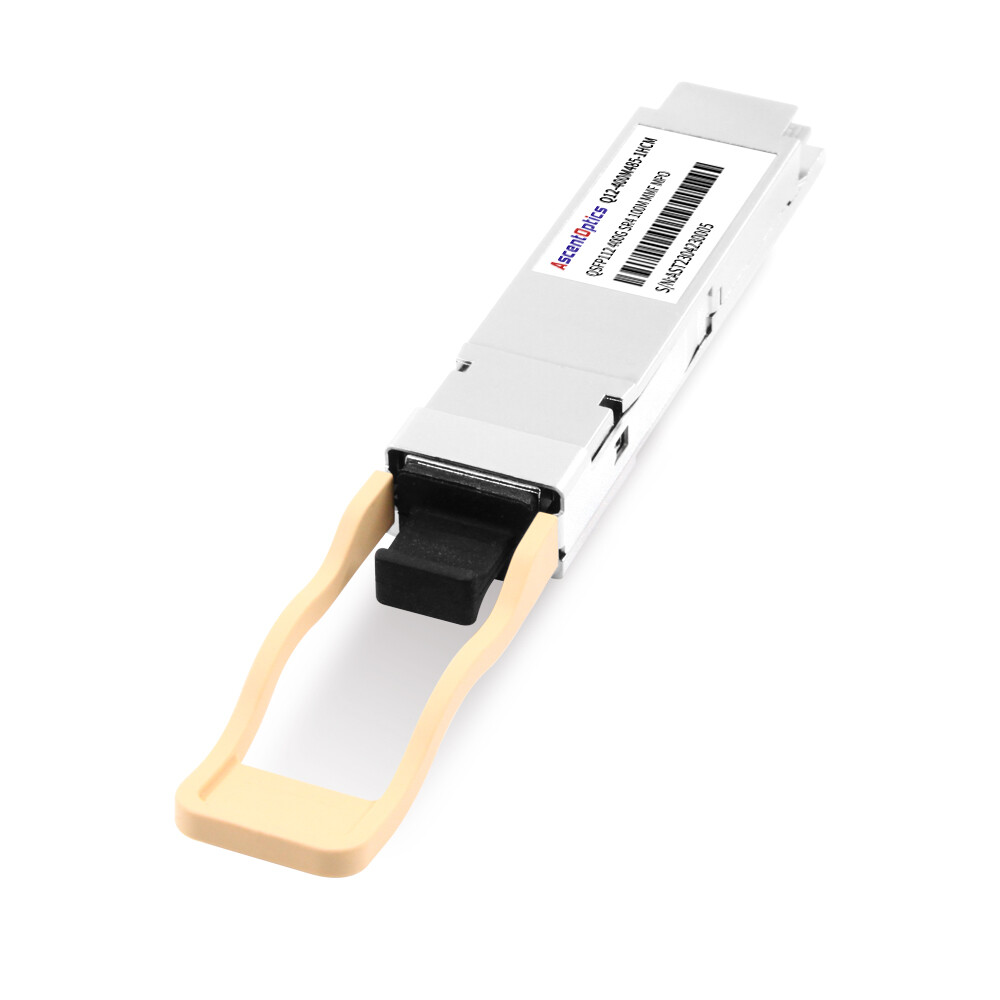
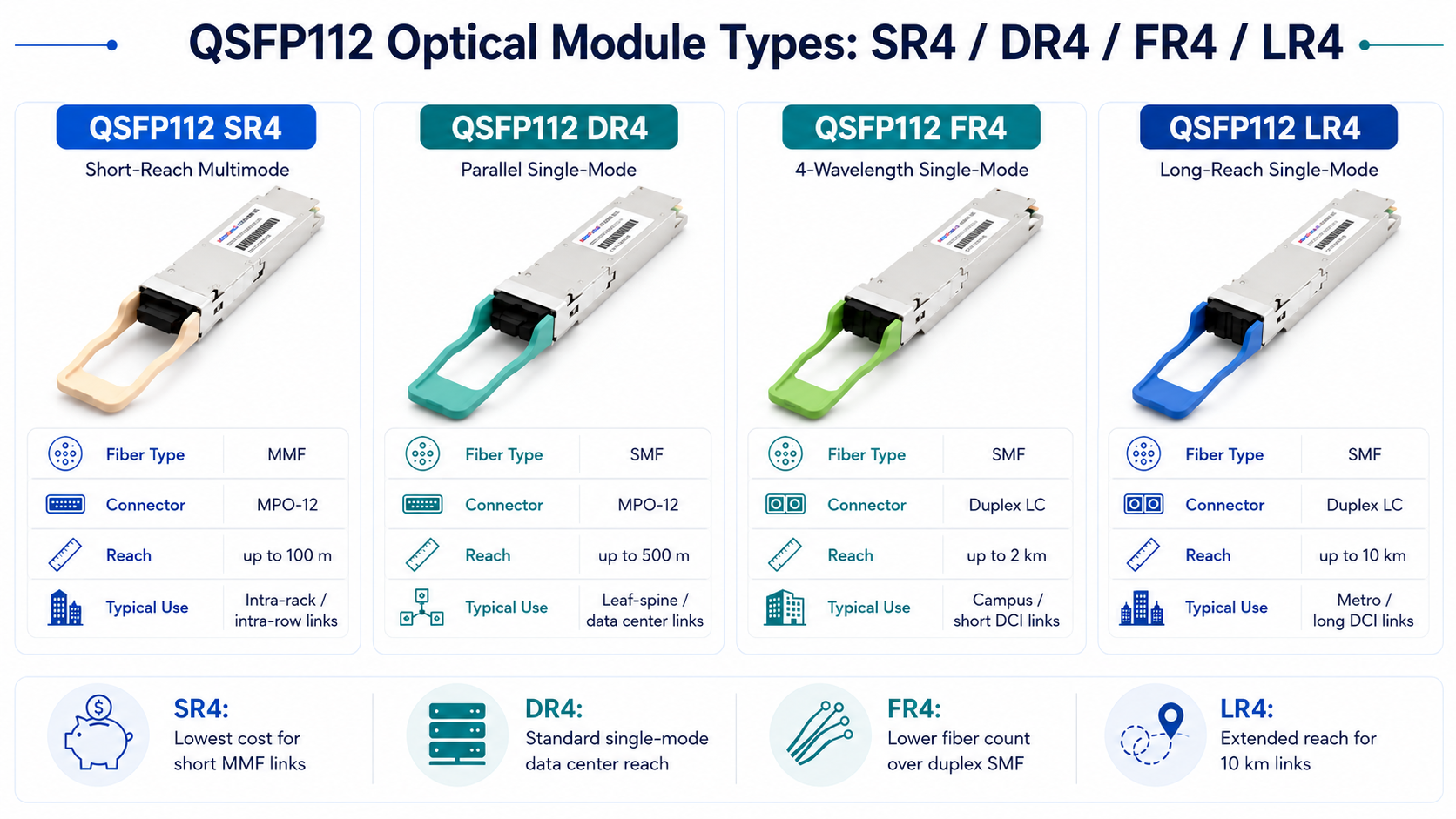
QSFP112-SR4 modules are designed for short multimode links inside data centers. They typically support up to 70 m over OM3 and up to 100 m over OM4 multimode fiber, with some vendor-specific implementations also listing OM5 support. These modules use parallel multimode optics and MPO/MTP connectivity, making them suitable for intra-rack and short intra-row connections.
QSFP112-DR4: Single-Mode to 500 Meters
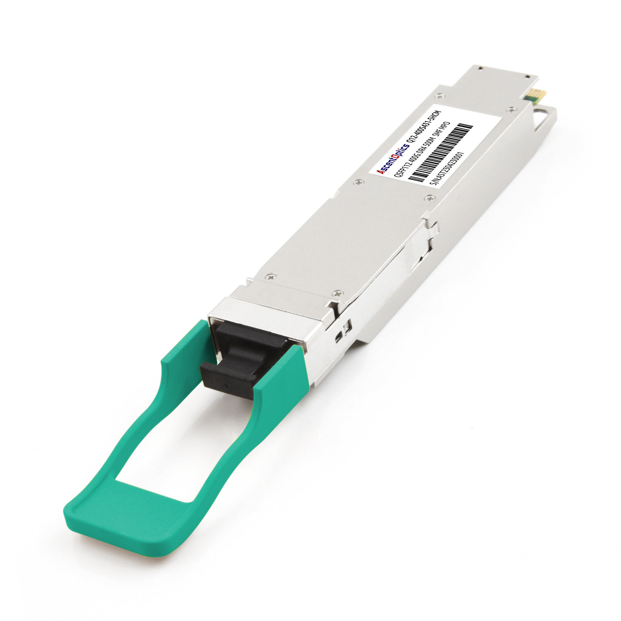
QSFP112-DR4 modules operate over single-mode fiber with parallel optics and MPO/MTP connectivity. They support distances up to 500 m and are widely used for leaf-to-spine links where multimode fiber cannot meet reach or loss requirements. DR4 is often a practical baseline for modern single-mode data center fabrics because it avoids WDM complexity while covering many intra-facility distances.
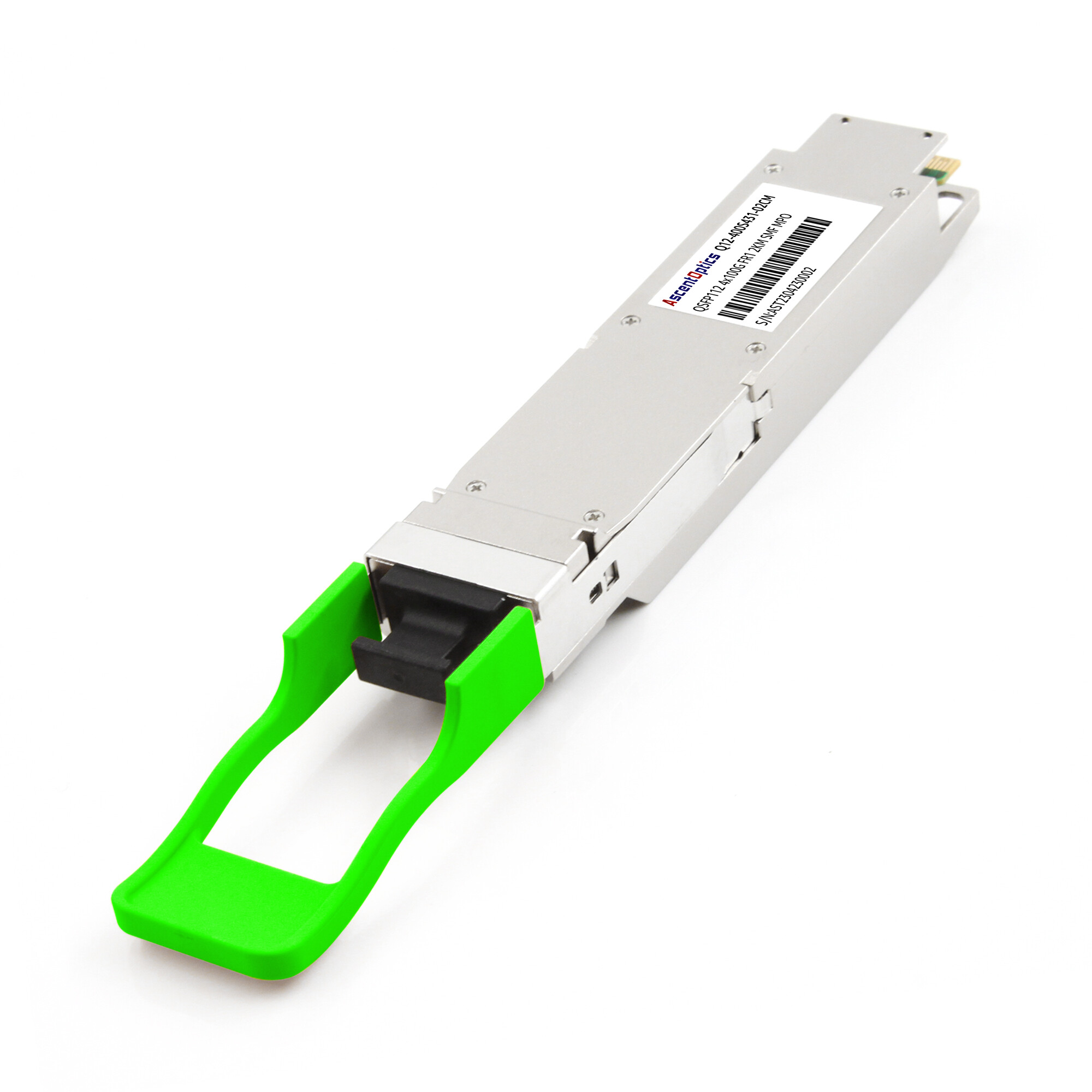
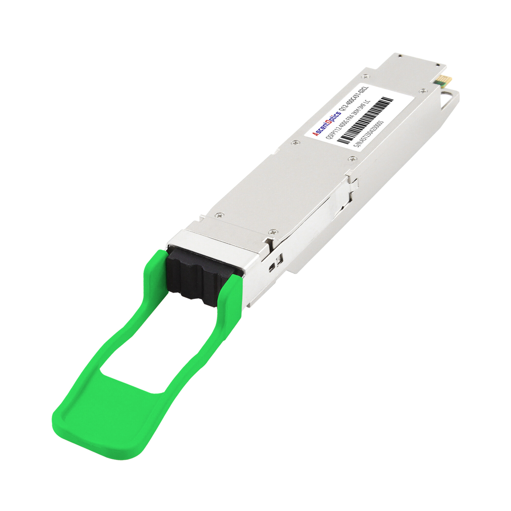
QSFP112-FR4 modules use four optical wavelengths multiplexed over a duplex single-mode fiber pair, normally with LC connectors. They support distances up to 2 km, making them suitable for campus links, large data centers, and short data center interconnects where fiber count is limited.
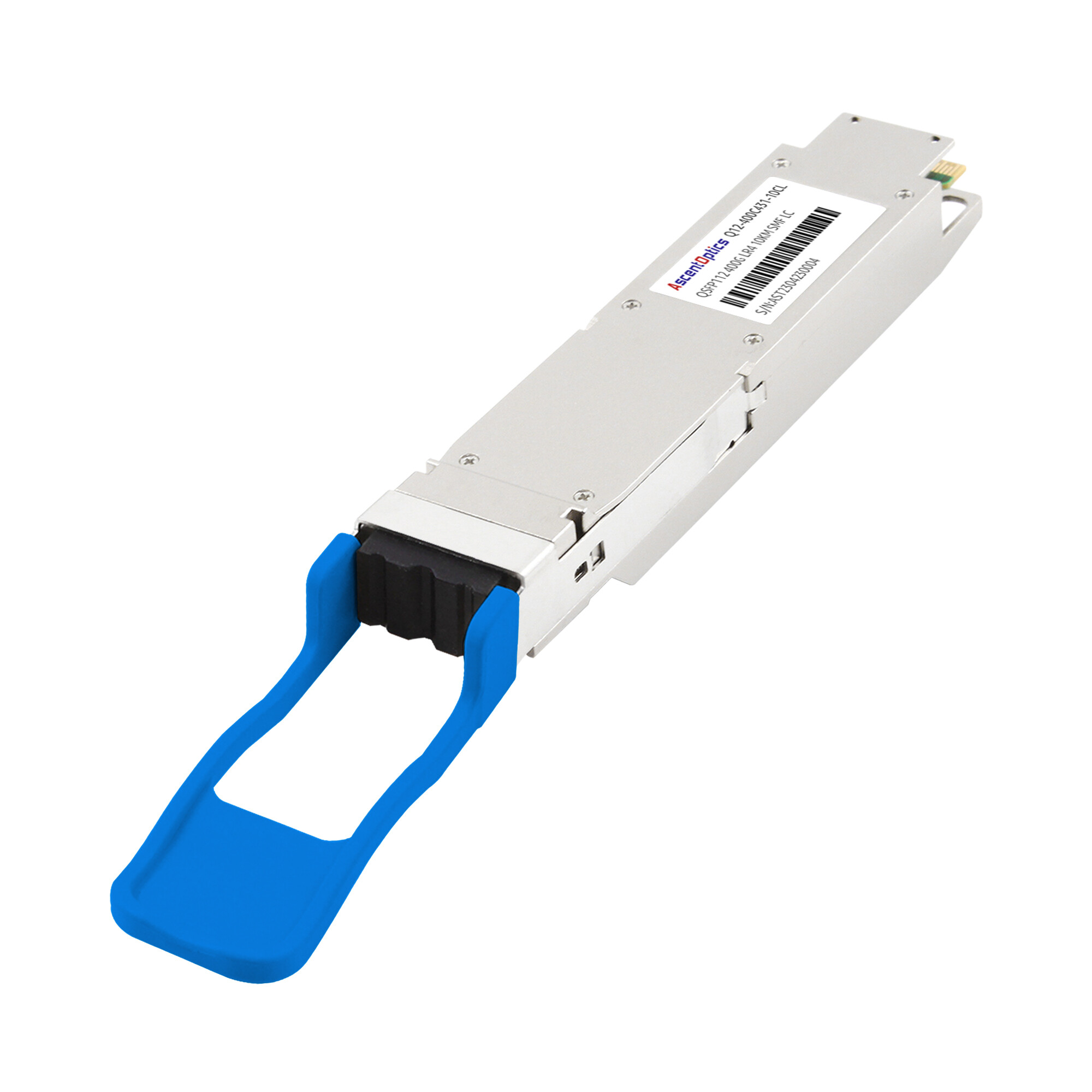
QSFP112-LR4 modules extend the WDM approach to longer single-mode links, typically up to 10 km depending on the specific standard or vendor implementation. They are used for data center interconnect, metro aggregation, and telecom transport handoffs. The trade-off is higher cost and power compared with SR4, DR4, or FR4.
Decision Framework
Start with distance and fiber type. For short multimode links, choose SR4. For single-mode links up to 500 m, DR4 is usually the most direct option. For 500 m to 2 km, evaluate FR4 when duplex fiber conservation matters. For longer single-mode links, consider LR4 or another extended-reach 400G optic.
Then check connector layout and operational limits. SR4 and DR4 use parallel fiber and require careful MPO/MTP polarity management. FR4 and LR4 use duplex single-mode fiber and reduce fiber count, but they normally draw more power because of WDM optics and DSP requirements. Always compare actual datasheet values rather than relying on generic power ranges.
Looking for compatible QSFP112 modules for your switch platform? Explore our 400G QSFP112 optical transceiver solutions to find options matched to your network architecture and bandwidth requirements.
Power, Thermal, and Density Advantages
Power Consumption Comparison
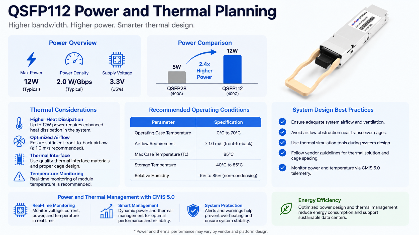
Power efficiency is one of the reasons QSFP112 is attractive, but the numbers must be stated carefully. Many 400G QSFP112 modules fall in the approximate 8 to 12 W range, while comparable QSFP-DD modules may fall in a similar or slightly higher range depending on reach, DSP design, and vendor generation. The best comparison is always variant-to-variant: SR4 vs SR4, DR4 vs DR4, FR4 vs FR4, and LR4 vs LR4.
At scale, even a small per-module difference matters. In a 32-port 400G switch, a 2 W difference per optic equals 64 W of optical power. Across hundreds of switches, that affects rack power distribution, UPS sizing, cooling capacity, and operating cost. For this reason, optics should be included in rack-level power budgets rather than treated as a minor accessory.
Thermal Design Benefits
QSFP112 can simplify thermal design because it delivers 400G through four host electrical lanes. Fewer high-speed host lanes can reduce host-side complexity, but module heat still depends on the optical engine, DSP, reach, ambient temperature, and switch airflow. A low-power DR4 module and a higher-power LR4 module should not be treated the same in thermal planning.
Thermal performance is also controlled by the host cage, heat sink, airflow direction, fan policy, and inlet temperature. Unlike OSFP, where flat-top and finned-top module styles are commonly discussed, QSFP-family platforms typically rely more heavily on host-side heat sinks and system airflow. In high-density 1U deployments, validate module case temperature and DOM readings during burn-in, not only after idle link-up.
Port Density in 1U Switches
QSFP112 preserves the compact QSFP front-panel footprint while enabling 400G-class connectivity. This allows vendors to build dense 400G switches without moving to larger physical module formats. However, QSFP-DD also uses a similar front-panel module size while adding a double-density electrical connector, and OSFP provides more thermal headroom at the cost of a larger module body. The best choice depends on the switch platform, cooling design, and migration strategy.
For data centers where rack space is expensive, 32-port 400G QSFP112 platforms can provide a strong balance of density and efficiency. The final design should still be validated against real optic power, airflow direction, inlet temperature, and serviceability requirements.
QSFP112 in AI and High-Performance Computing
400G Ethernet and InfiniBand Ecosystem
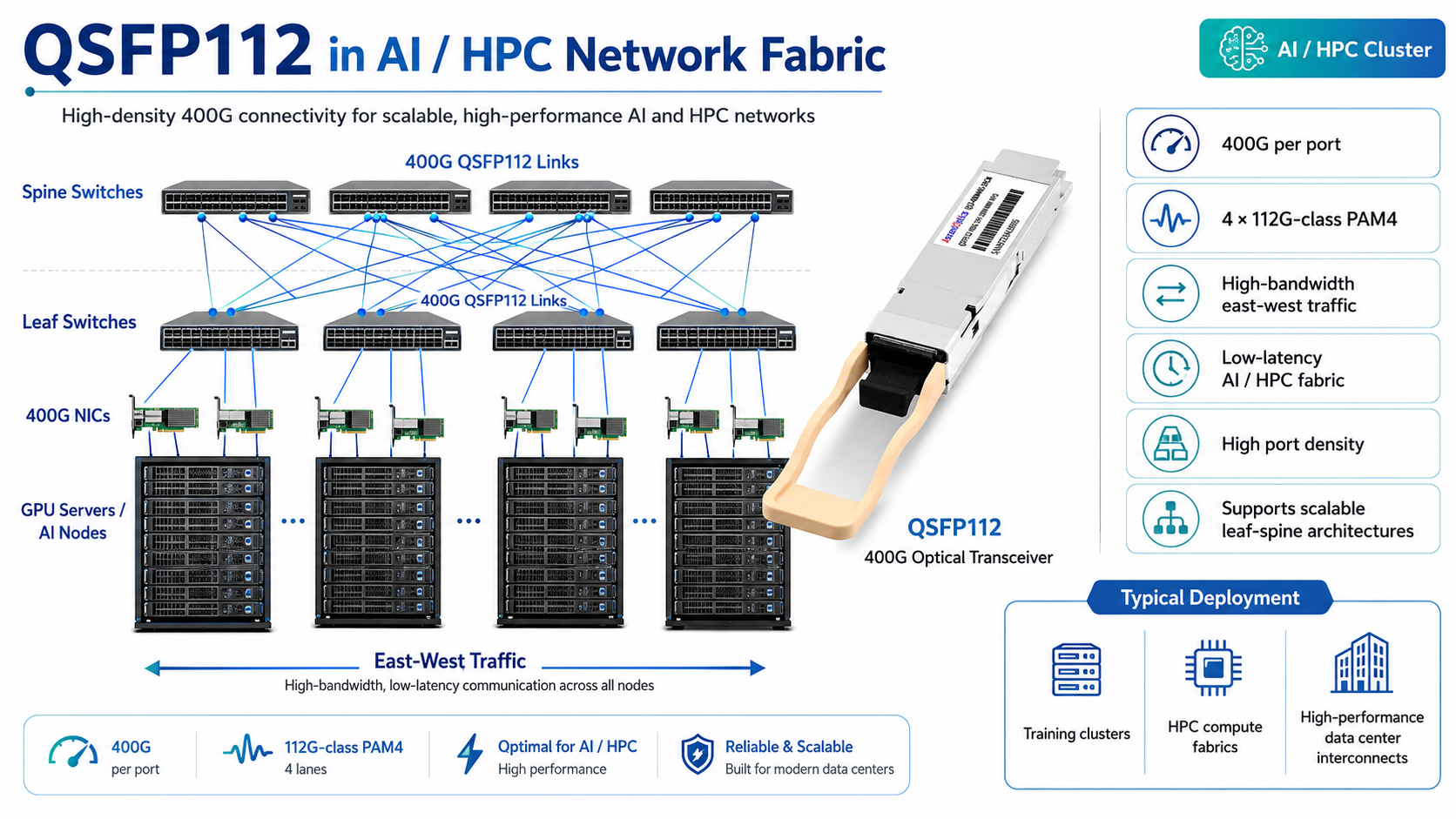
QSFP112 is relevant to AI and HPC because modern accelerators need high-bandwidth, low-latency network fabrics. ConnectX-7 adapter cards are available in high-speed 400G Ethernet and NDR InfiniBand configurations, and some adapter SKUs use QSFP112 ports. However, not every NVIDIA 400G platform uses QSFP112. For example, many NVIDIA Quantum-2 switch systems are built around OSFP physical connectors. Engineers should verify the exact adapter and switch SKU before standardizing optics.
This distinction is important in mixed AI fabrics. A cluster may use QSFP112 NICs, OSFP switches, OSFP-to-QSFP112 cables, or transceivers with different host interfaces. Inventory planning should therefore be based on the exact port type and cable map, not only on the advertised 400G/NDR speed.
AI Cluster Architecture
When Dr. Elena Vasquez’s research team at a European university began building a 512-GPU cluster for climate modeling, they selected 400G-class NICs and switches to support high east-west bandwidth. The team’s cabling plan was based on the actual port mix in each rack: short passive or active copper where supported, SR4 for short multimode optical links, and DR4 for longer single-mode spine connections. By standardizing the link plan early, they reduced adapter-cable complexity and avoided last-minute compatibility issues.
AI clusters typically use fat-tree, dragonfly, or rail-optimized topologies. QSFP112 can provide high-bandwidth server or switch ports in these designs, but topology efficiency depends on the entire system: GPU count, NIC count, oversubscription ratio, switch radix, cable length, and protocol stack. The module form factor is only one part of the architecture.
Low-Latency Considerations
Latency should not be oversold as an inherent QSFP112 advantage. Four-lane designs can reduce some host-side complexity compared with eight-lane implementations, but optical-module latency depends heavily on the DSP, FEC mode, retimers, cable type, and switch ASIC. For latency-sensitive AI and HPC workloads, validate the full link path under production settings rather than assuming one form factor is always faster.
Compatibility, Cabling, and Breakout Options
Switch and Platform Compatibility
Not all 400G ports are QSFP112 ports. Some 400G switches use QSFP-DD, some use OSFP, and some use QSFP112. The critical requirement is support for the correct electrical lane rate and the exact module form factor. A 400G port based on eight 50G PAM4 electrical lanes is not the same as a four-lane QSFP112 port, even if both are advertised as 400G.
Firmware support is also essential. CMIS defines how the host reads module identity, diagnostics, thresholds, alarms, power classes, and control functions. Older firmware may misidentify a module, report inaccurate DOM values, or fail to apply the correct power and FEC settings. Before procurement, check the switch vendor’s supported optic list, NOS version, and release notes.
DAC and AOC Cable Options
For very short reaches, QSFP112 direct attach copper cables may be used when the host platform supports them. Passive copper is typically limited to very short intra-rack distances. Active copper or active electrical cables can extend reach, depending on cable construction and host support. Active optical cables extend farther, commonly into the 10 m to 100 m range depending on the product.
Cable qualification is especially important at 112G-class lane rates. Insertion loss, cable length, retimer behavior, host equalization, and FEC settings can determine whether a cable that links up in the lab remains stable in production temperature conditions.
Breakout Configurations
Breakout support must be described carefully. A 400G QSFP112 port uses four high-speed host lanes, so it can only break out when the switch ASIC, firmware, and cable assembly support the target lane mapping. Some platforms support 2x200G or 4x100G breakout modes, but this is not the same as saying any QSFP112 port can passively fan out to four standard QSFP28 100G modules.
The reason is electrical. A traditional 100G QSFP28 port usually expects four 25G NRZ electrical lanes, while a QSFP112 400G port provides four 100G/112G PAM4-class lanes. Direct breakout from one QSFP112 port to four QSFP28 endpoints generally requires compatible host modes, active conversion, or endpoints designed for 100G single-lambda operation. Always verify breakout support in the switch port guide and optic/cable datasheet before designing a migration around it.
For a broader look at when to choose copper versus optical cabling, our comparison of DAC and AOC cables covers the factors that guide cable selection in high-speed networks.
Conclusion
QSFP112 transceivers offer a compact and efficient path to 400G for data centers, AI clusters, and high-performance computing environments. Their main advantage is not “universal backward compatibility,” but the ability to deliver 400G-class performance through a four-lane QSFP-family interface when the host platform is designed for it.
The key takeaways for network engineers are straightforward. Match the optical variant to the actual distance, fiber type, connector, and loss budget. Use SR4 for short multimode links, DR4 for single-mode links up to 500 m, FR4 for duplex single-mode links up to 2 km, and LR4-class optics for longer 10 km-class reaches. Verify ASIC lane rate, cage type, firmware, CMIS support, FEC mode, and vendor compatibility before procurement. Treat breakout as a platform-specific feature, not a universal capability.
400G is no longer a future-state technology reserved for hyperscalers. With QSFP112, enterprise and regional data centers can deploy the bandwidth that AI, cloud, and distributed applications demand without the complexity of earlier 400G transitions. The modules are available, the switches are shipping, and the standards are stable.
Ready to evaluate QSFP112 transceivers for your network? Contact our optical networking experts to discuss compatibility, module selection, and custom optical solutions for your data center or AI cluster deployment.
FAQs About QSFP112 Transceivers
Q1: What is a QSFP112 transceiver?
A QSFP112 transceiver is a 400G-class optical module based on four high-speed electrical lanes. Each lane uses 100G/112G-class PAM4 signaling, allowing the module to support 400G Ethernet or 400G-class InfiniBand links in a compact QSFP-family form factor. It is commonly used in data centers, AI clusters, HPC networks, and high-density spine-leaf architectures.
Q2: Is QSFP112 the same size as QSFP28?
QSFP112 belongs to the QSFP form factor family and keeps a similar front-panel footprint to QSFP28 and QSFP56. However, similar size does not mean full compatibility. A QSFP112 module requires a host port designed for 112G-class PAM4 signaling, proper signal integrity, firmware support, and sufficient thermal design. A QSFP28-only port cannot run a QSFP112 module at 400G.
Q3: What is the main difference between QSFP112 and QSFP28?
The main difference is the electrical lane speed and modulation format. QSFP28 typically supports 100G using four 25G NRZ electrical lanes. QSFP112 supports 400G using four 100G/112G-class PAM4 electrical lanes. The lane count is still four, but QSFP112 carries much more data per lane and requires a more advanced switch ASIC, PCB design, firmware, and thermal environment.
Q4: Can a QSFP112 port support QSFP28 modules?
Some QSFP112-capable ports may support QSFP28 modules in lower-speed mode, but this depends on the switch or network adapter. The host platform must support the required port speed, lane mapping, firmware profile, and module management interface. Always check the switch vendor’s compatibility list before assuming backward compatibility.
Q5: Can a QSFP28 port support a QSFP112 module?
No. A QSFP28 port cannot run a QSFP112 module at 400G because QSFP28 ports are normally built for 25G NRZ electrical lanes, while QSFP112 requires 100G/112G-class PAM4 electrical lanes. Even if the module appears to fit mechanically, the electrical interface is not compatible.
Q6: What are the common QSFP112 optical module types?
The most common 400G QSFP112 optical modules include QSFP112-SR4, QSFP112-DR4, QSFP112-FR4, and QSFP112-LR4. SR4 is used for short multimode fiber links, DR4 is used for parallel single-mode fiber links up to 500 m, FR4 is used for duplex single-mode fiber links up to 2 km, and LR4 is used for longer 10 km-class single-mode links. These module types match the reach categories already discussed in the article.
Q7: Which QSFP112 module should I choose for a data center?
For short multimode links inside a rack or between nearby racks, QSFP112-SR4 is usually the most cost-effective choice. For single-mode leaf-to-spine links up to 500 m, QSFP112-DR4 is often preferred. For duplex single-mode fiber up to 2 km, QSFP112-FR4 is suitable. For longer data center interconnect or metro links, QSFP112-LR4 is the better option.
Q8: Does QSFP112 use MPO or LC connectors?
It depends on the optical variant. QSFP112-SR4 and QSFP112-DR4 usually use parallel fiber with MPO/MTP connectors. QSFP112-FR4 and QSFP112-LR4 usually use duplex single-mode fiber with LC connectors because they rely on wavelength multiplexing over a fiber pair.
Q9: Can QSFP112 break out to 4×100G QSFP28?
This depends on the host platform and cable design. A 400G QSFP112 port uses four 100G/112G-class PAM4 electrical lanes, while a traditional 100G QSFP28 port usually uses four 25G NRZ lanes. Because of this electrical difference, QSFP112 to 4×QSFP28 is not a universal passive breakout option. It requires switch ASIC support, firmware support, correct port mode, and a compatible breakout cable or active conversion solution.
Q10: Can QSFP112 be used in AI and HPC networks?
Yes. QSFP112 is suitable for AI and HPC networks that require high-bandwidth, low-latency 400G-class connectivity. It can be used for GPU cluster interconnects, spine-leaf fabrics, and high-speed server-to-switch connections. However, engineers should confirm the actual port type on each NIC and switch, because some 400G AI platforms use QSFP112, while others use OSFP or QSFP-DD.
Q11: Is QSFP112 suitable for upgrading from 100G to 400G?
Yes, QSFP112 can be a good upgrade path from 100G to 400G when the new switch or NIC supports 112G-class PAM4. It is especially useful for high-density 400G deployments where rack space and port density are important. However, the upgrade should be planned as a full system migration, not simply a module replacement. The host platform, optics, fiber plant, firmware, and thermal design all need to be validated.
Post Views: 1,890