Some product comparisons imply that QSFP112 is simply the newer, lower-power replacement for QSFP-DD. That is only partly true. QSFP112 is an efficient 400G form factor built around a 4-lane, 112G-class PAM4 electrical interface, while QSFP-DD is a double-density QSFP architecture built around 8 electrical lanes and a broader forward path to higher speeds such as QSFP-DD800.
For data center engineers, this is not just a specification-table difference. It affects switch ASIC selection, port wiring, firmware support, optics inventory, thermal planning, and whether legacy QSFP28 or QSFP56 modules can be reused during a staged migration.
This guide compares QSFP-DD and QSFP112 from a practical deployment perspective. It explains how each form factor achieves 400G, where compatibility traps occur, how power and thermal differences affect rack planning, and how to build a migration plan that procurement, network operations, and data center facilities teams can all support.
How QSFP-DD and QSFP112 Achieve 400G
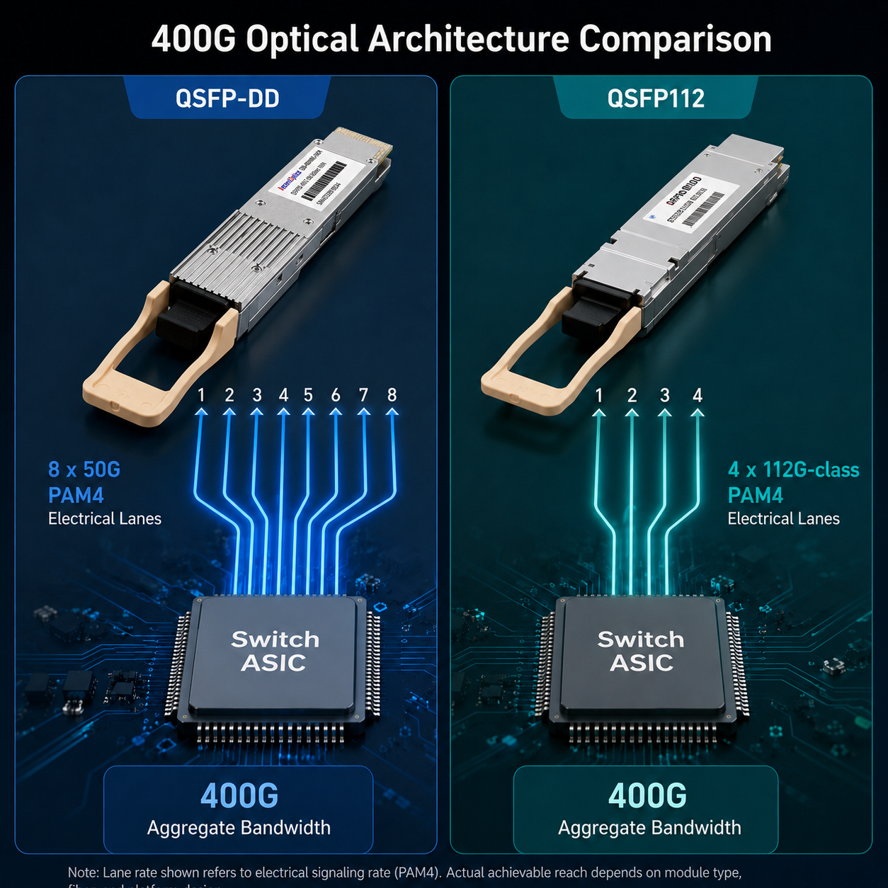
Both form factors can deliver 400G aggregate port bandwidth, but they do it with different host-side electrical architectures.
QSFP-DD: Parallel Lane Scaling
QSFP-DD stands for Quad Small Form-factor Pluggable Double Density. For 400G operation, the host electrical interface is commonly based on eight 50G-class PAM4 lanes. The double-density connector adds a second row of electrical contacts compared with classic QSFP, allowing twice the number of electrical lanes in a similar front-panel footprint.
This 8-lane approach reduces the required rate per electrical lane compared with 112G-class interfaces. It can simplify signal-integrity margins at the lane level, although it also increases lane count, connector complexity, and PCB routing density. Actual implementation difficulty depends on the switch ASIC, PCB material, trace length, retimers, and system design.
QSFP-DD also has a clear family roadmap. QSFP-DD800 uses eight 100G-class PAM4 lanes for 800G, while newer QSFP-DD variants extend the roadmap further. That does not mean every 400G QSFP-DD switch can be upgraded to 800G by optics alone; the host ASIC and port design must support the required lane rate.
QSFP112: Per-Lane Speed Scaling
QSFP112 keeps the traditional 4-lane QSFP concept but raises the electrical lane rate to the 100G/112G PAM4 class. The result is a 400G module architecture with fewer host-side electrical lanes than QSFP-DD 400G.
In practice, QSFP112 should be described as using 4 x 112G-class PAM4 SerDes rather than simply 4 x 112G = 448G. Ethernet and InfiniBand implementations include coding, FEC, and protocol overhead, so the exact line rate depends on the standard and host interface. The important point is that QSFP112 uses four high-speed PAM4 lanes to support 400G-class connectivity.
The benefit is a simpler 4-lane electrical path and potentially lower module power for comparable reach types. The trade-off is that 112G-class PAM4 channels are more sensitive to insertion loss, crosstalk, return loss, connector quality, and thermal noise. QSFP112 therefore belongs in hosts specifically designed and validated for 112G-class SerDes operation.
Why the Architecture Difference Matters
The 8-lane versus 4-lane distinction determines whether a module can establish a link. The cage is only the mechanical opening. The host ASIC, connector pinout, lane count, SerDes rate, FEC mode, and firmware determine electrical compatibility. Treating QSFP-DD and QSFP112 as interchangeable 400G optics is one of the most common procurement mistakes in 400G migration projects.
QSFP-DD vs QSFP112: Head-to-Head Technical Comparison
The following comparison table summarizes the core technical parameters that drive procurement decisions.
| Specification |
QSFP-DD |
QSFP112 |
| Electrical interface |
8 x 50G PAM4 |
4 x 112G PAM4 |
| Aggregate bandwidth |
400G / 800G (QSFP-DD800) |
400G only |
| Typical power consumption |
10W to 14W |
8W to 12W |
| Physical dimensions |
18.35 x 89.4 x 8.5 mm |
18.4 x 89.4 x 8.5 mm |
| Backward compatibility with QSFP28 |
Native (ASIC-dependent) |
Limited (ASIC-dependent) |
| Forward path to 800G |
QSFP-DD800 (8 x 100G) |
No native upgrade path |
| Primary ecosystem |
Cisco, Juniper, Arista enterprise |
NVIDIA, select Arista, AI/HPC |
| Signal integrity margin |
Wider (lower per-lane rate) |
Narrower (higher per-lane rate) |
| Thermal distribution |
Spread across 8 lanes |
Concentrated in 4 lanes |
Electrical Interface and Signal Integrity
QSFP-DD 400G distributes the host electrical interface across eight lanes. This can provide more margin at the individual lane level than a 112G-class channel, but it also requires more host lanes, a double-density connector, and denser board routing. The correct conclusion is not that QSFP-DD is always easier to design; it is that the design challenge is different.
QSFP112 concentrates the host interface into four 112G-class lanes. This reduces lane count and can simplify routing topology, but each lane has a tighter electrical budget. Successful deployment depends on a host platform designed for 112G PAM4, with validated channel loss, equalization, FEC behavior, and thermal performance.
Power Consumption and Thermal Performance
Power is one of the strongest arguments for QSFP112, but the comparison must be made carefully. A QSFP112 DR4 module should be compared with a QSFP-DD DR4 module from the same generation and similar vendor class. SR4, DR4, FR4, LR4, ZR, and ZR+ optics have very different power profiles.
For many 400G client optics, QSFP112 modules are commonly quoted in the 8W to 12W planning range, while comparable QSFP-DD client optics often fall around 10W to 14W. A 2W to 4W difference per port can matter in dense racks, but the final value must come from the exact module datasheet.
Thermally, lower total power usually helps. However, QSFP112 still places high-speed 112G-class electronics into a compact 4-lane module, so host airflow, cage design, heat-sink contact, fan policy, ambient temperature, and DOM telemetry must be validated under full-port population.
Backward Compatibility Reality Check
QSFP-DD was designed to preserve QSFP-family mechanical compatibility. A QSFP-DD cage can physically accept certain legacy QSFP modules, but link operation still depends on the host ASIC and firmware supporting the required lane mode and speed. Physical insertion does not guarantee link-up.
QSFP112 uses the QSFP-family 4-lane concept, but backward compatibility with QSFP28 or QSFP56 is also host dependent. Some ports can operate in lower-speed modes; others are fixed for 400G-class operation. Always check the switch or NIC datasheet, supported breakout modes, and vendor transceiver qualification list before ordering modules.
800G Roadmap: Verified Interpretation
QSFP-DD has a defined path beyond 400G through QSFP-DD800 and newer QSFP-DD generations. That makes it attractive when a three-to-five-year roadmap includes 800G or higher front-panel bandwidth.
QSFP112 itself should be treated as a 400G form factor. It does not provide a native 800G upgrade path inside the same 4-lane 112G architecture. To reach 800G, networks typically move to QSFP-DD800, OSFP, or future 224G/lane ecosystems. A vendor may discuss future 224G/lane evolution, but that is not the same as saying a QSFP112 400G deployment upgrades directly to 800G by replacing optics.
Need help deciding between 400G form factors? See how QSFP112 compares to QSFP-DD across power, compatibility, and forward scalability.
QSFP112 Module Types: SR4, DR4, FR4, and LR4
QSFP112 is not a single optical specification. It is a 400G form factor and electrical interface family that can support multiple optical reaches. Choosing the right QSFP112 module depends on three practical factors: link distance, installed fiber type, and connector availability.
The most common QSFP112 optical module types are SR4, DR4, FR4, and LR4. They all provide 400G connectivity, but they use different optical architectures and serve different deployment scenarios.
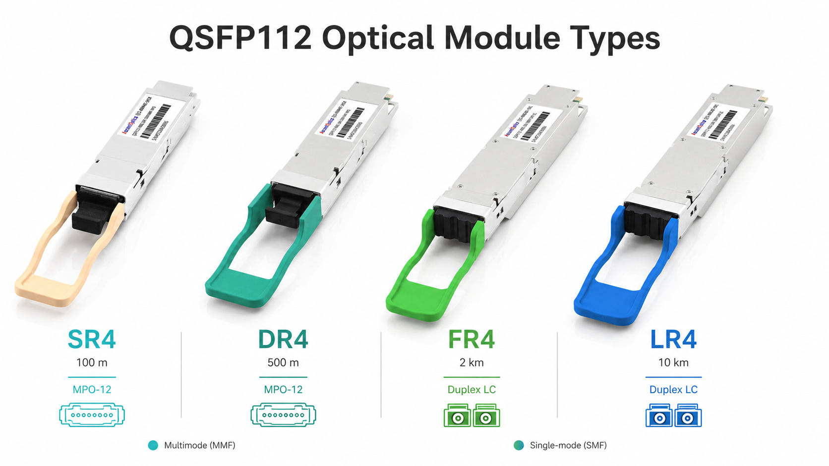
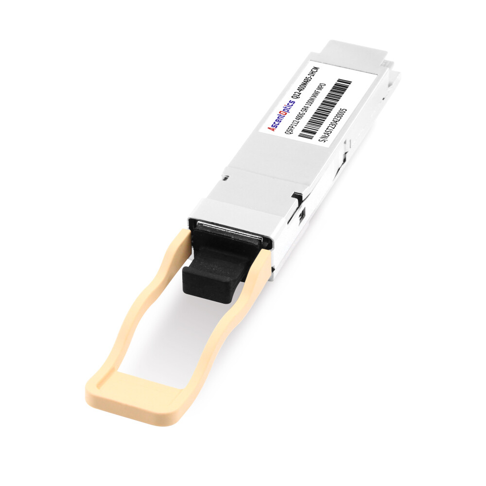
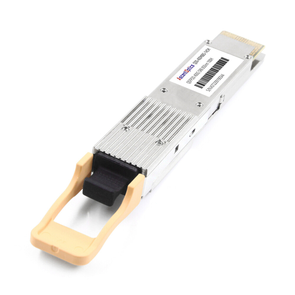
QSFP112 SR4: Short-Reach Multimode
QSFP112 SR4 is designed for short-distance 400G links over multimode fiber. It typically uses an MPO-12 connector and four parallel optical lanes. Each lane carries one direction of traffic over multimode fiber, making SR4 a natural fit for intra-rack and intra-row connections inside data centers.
SR4 is usually the most cost-effective QSFP112 option when OM3 or OM4 multimode fiber is already installed. A typical deployment supports up to 70 meters over OM3 and up to 100 meters over OM4, depending on the module vendor and link budget.
Choose QSFP112 SR4 when:
- •The link distance is within 100 meters.
- •Existing multimode MPO cabling is available.
- •The connection is inside the same rack, row, or nearby data hall area.
- •Lowest optical module cost is more important than fiber count reduction.
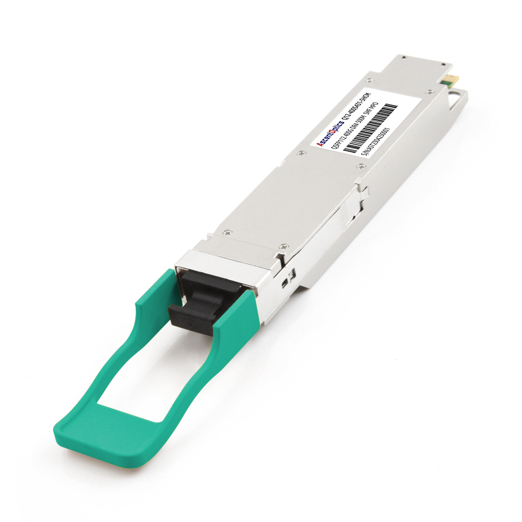
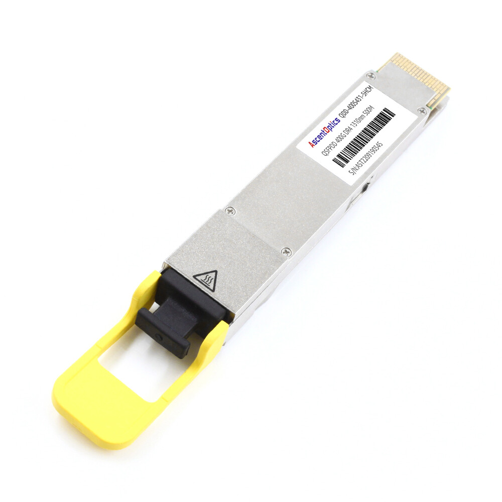
QSFP112 DR4: Parallel Single-Mode to 500 Meters
QSFP112 DR4 uses four parallel single-mode optical lanes and typically supports distances up to 500 meters over OS2 single-mode fiber. Like SR4, it usually uses an MPO-12 connector, but the fiber type is single-mode rather than multimode.
DR4 is commonly used for leaf-spine links, rack-to-rack links, and short data center interconnects where multimode fiber is not suitable. It is also useful in facilities that have standardized on single-mode fiber for better long-term scalability.
Choose QSFP112 DR4 when:
- •The link distance is up to 500 meters.
- •The data center uses OS2 single-mode fiber.
- •Parallel MPO cabling is available or acceptable.
- •You need a practical 400G option for leaf-spine or building-level links.
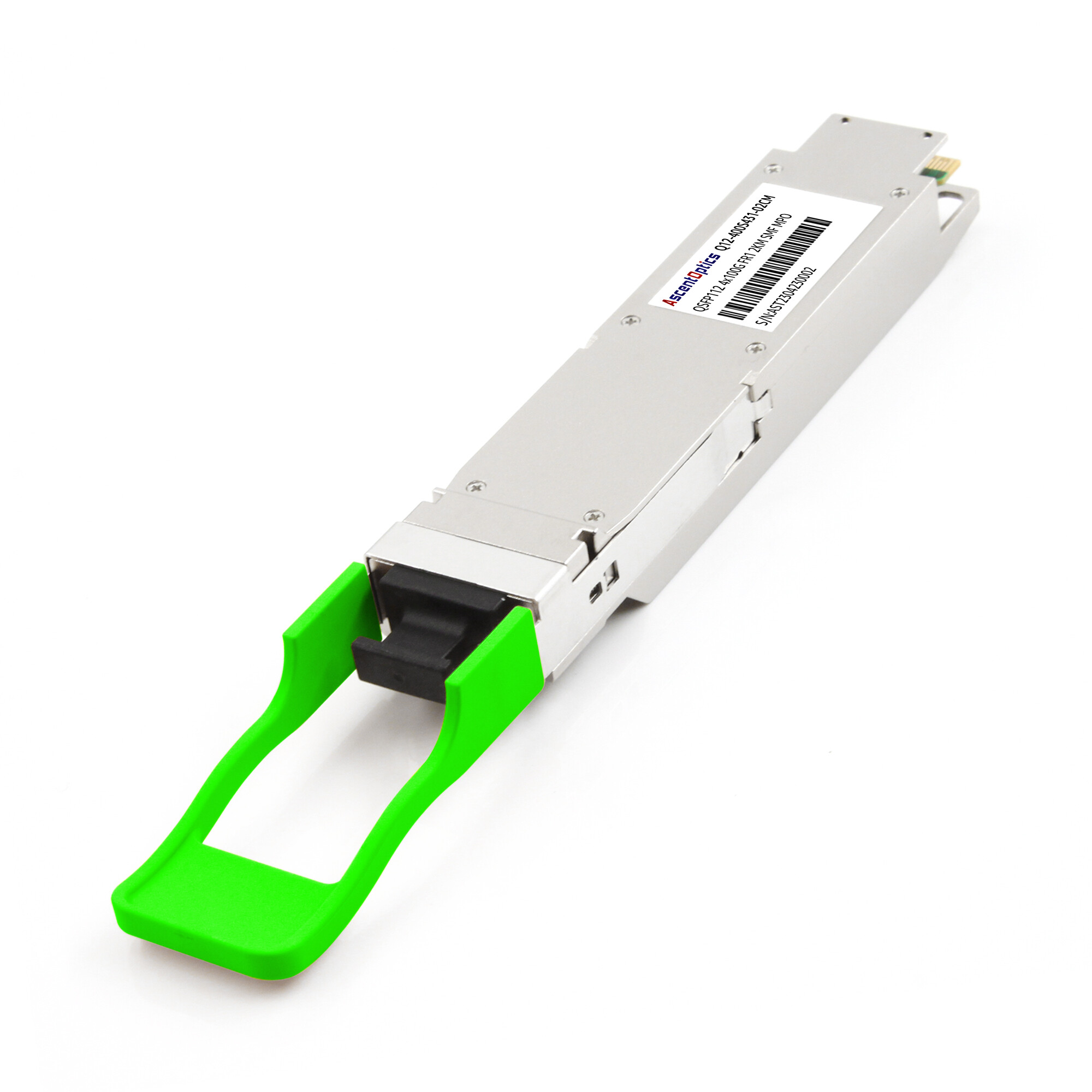
QSFP112 FR4: 2 km Duplex Single-Mode
QSFP112 FR4 uses four optical wavelengths multiplexed over a duplex single-mode fiber pair. Unlike SR4 and DR4, which use parallel fiber, FR4 typically uses a duplex LC connector. This reduces fiber count and makes FR4 easier to deploy where duplex single-mode fiber is already installed.
FR4 is commonly used for campus links, short data center interconnects, and aggregation layers where the link distance exceeds DR4 but does not require 10 km reach. Because FR4 uses WDM optics, it is usually more expensive and consumes more power than SR4 or DR4, but it can significantly simplify cabling.
Choose QSFP112 FR4 when:
- •The link distance is up to 2 km.
- •Duplex LC single-mode fiber is preferred or already installed.
- •Fiber count is limited.
- •You need 400G connectivity between buildings, rooms, or nearby facilities.
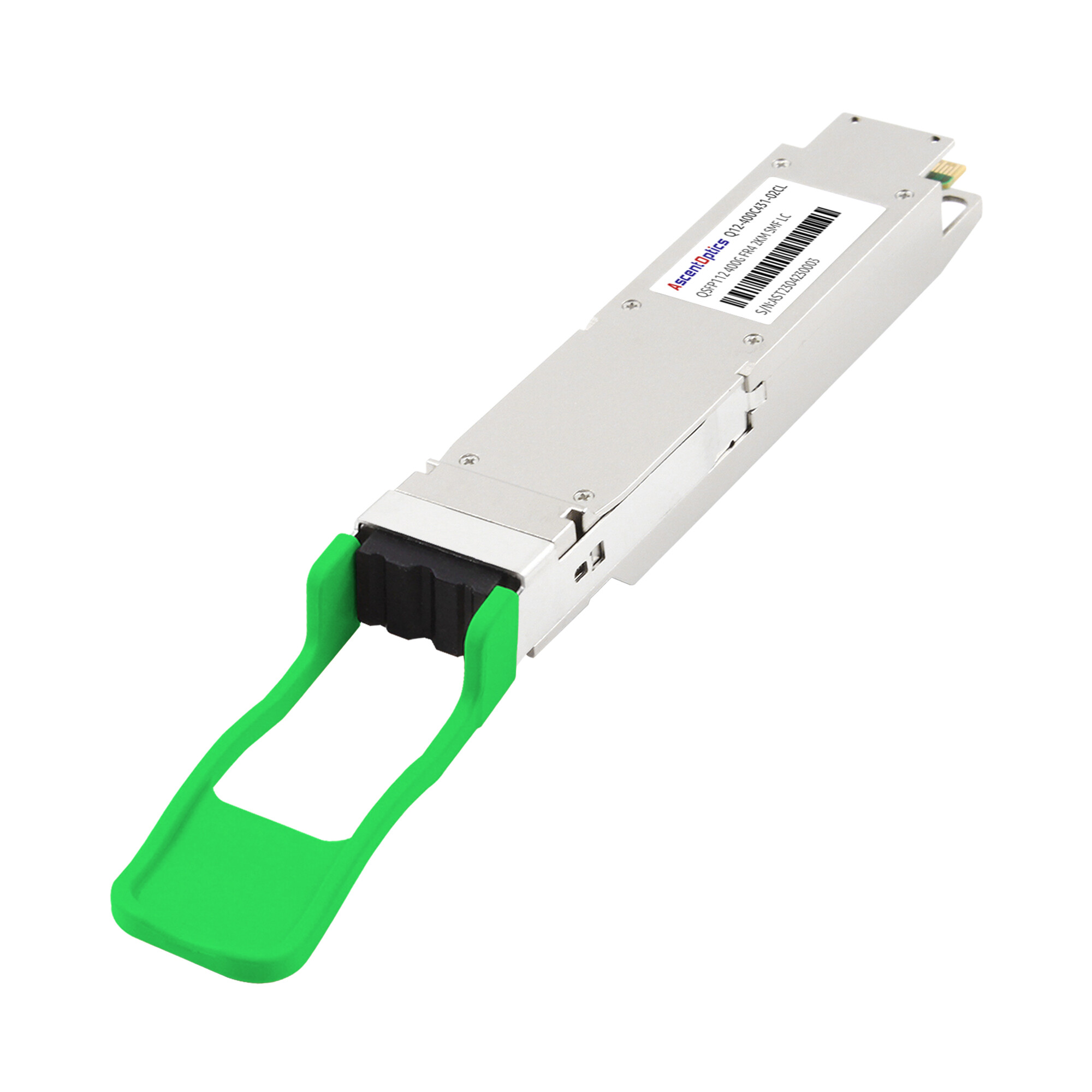
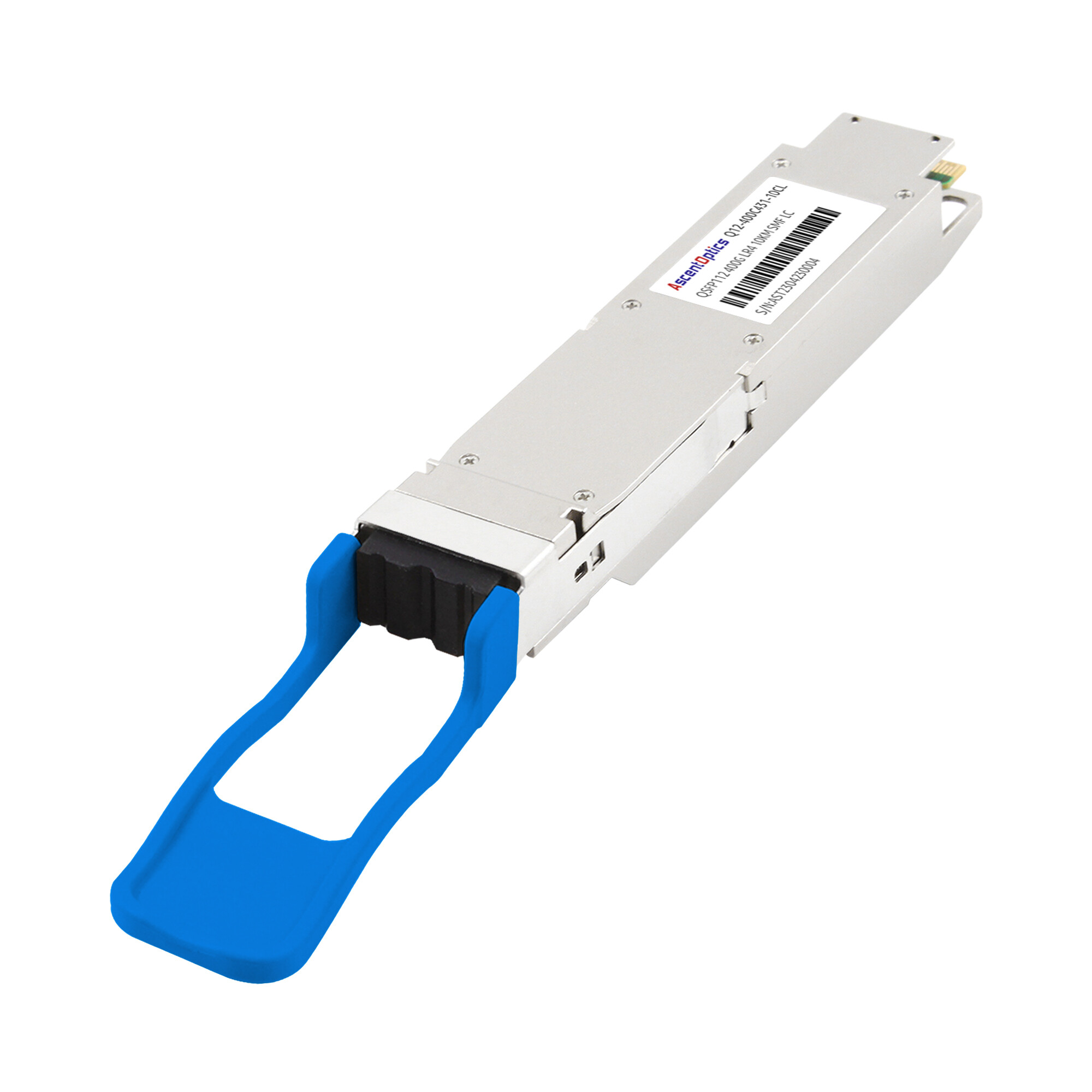
QSFP112 LR4: 10 km Long-Reach Single-Mode
QSFP112 LR4 extends the same duplex single-mode concept to longer distances, typically up to 10 km. It also uses WDM technology over a duplex LC interface, making it suitable for metro, long-reach data center interconnect, and carrier or enterprise backbone applications.
LR4 modules usually have higher optical complexity, higher power consumption, and higher cost than SR4, DR4, or FR4. For this reason, LR4 should be selected only when the link distance requires it.
Choose QSFP112 LR4 when:
- •The link distance is beyond 2 km and up to 10 km.
- •Duplex OS2 single-mode fiber is available.
- •The application involves metro DCI, campus backbone, or long-reach enterprise interconnect.
- •Higher module cost and power consumption are acceptable for extended reach.
QSFP112 Module Selection Summary
| Module Type |
Fiber Type
|
Connector
|
Typical Reach
|
Best Use Case |
| QSFP112 SR4 |
Multimode fiber
|
MPO-12
|
Up to 70 m OM3 / 100 m OM4
|
Intra-rack and intra-row data center links |
| QSFP112 DR4 |
Single-mode fiber
|
MPO-12 |
Up to 500 m
|
Leaf-spine and short data center links |
| QSFP112 FR4 |
Single-mode fiber
|
Duplex LC |
Up to 2 km
|
Campus, aggregation, and short DCI links |
| QSFP112 LR4 |
Single-mode fiber |
Duplex LC
|
Up to 10 km
|
Metro, backbone, and long-reach DCI links |
In practice, the selection process should start with the fiber plant, not the module name. The key point is that QSFP112 defines the host-side 400G electrical interface, but the optical side still varies by reach and fiber type. Before procurement, always confirm the module variant, connector, fiber type, reach, power class, and switch compatibility against the actual platform datasheet.
Looking for compatible QSFP112 modules for your switch platform? Explore our 400G QSFP112 optical transceiver solutions to find options matched to your network architecture and bandwidth requirements.
The Compatibility Trap: What Physical Fit Does Not Mean
The most dangerous assumption in 400G procurement is that a module that fits mechanically will work electrically. QSFP-DD, QSFP112, QSFP56, and QSFP28 all share parts of the QSFP mechanical family, but the electrical lane count and SerDes rate can be very different.
A QSFP112 module may fit into a QSFP-DD cage that supports QSFP-family modules, but that does not mean the port can run a 4-lane 112G-class interface. Likewise, a QSFP28 module may fit into a QSFP112-capable cage, but that does not guarantee the port can fall back to 4 x 25G NRZ operation.
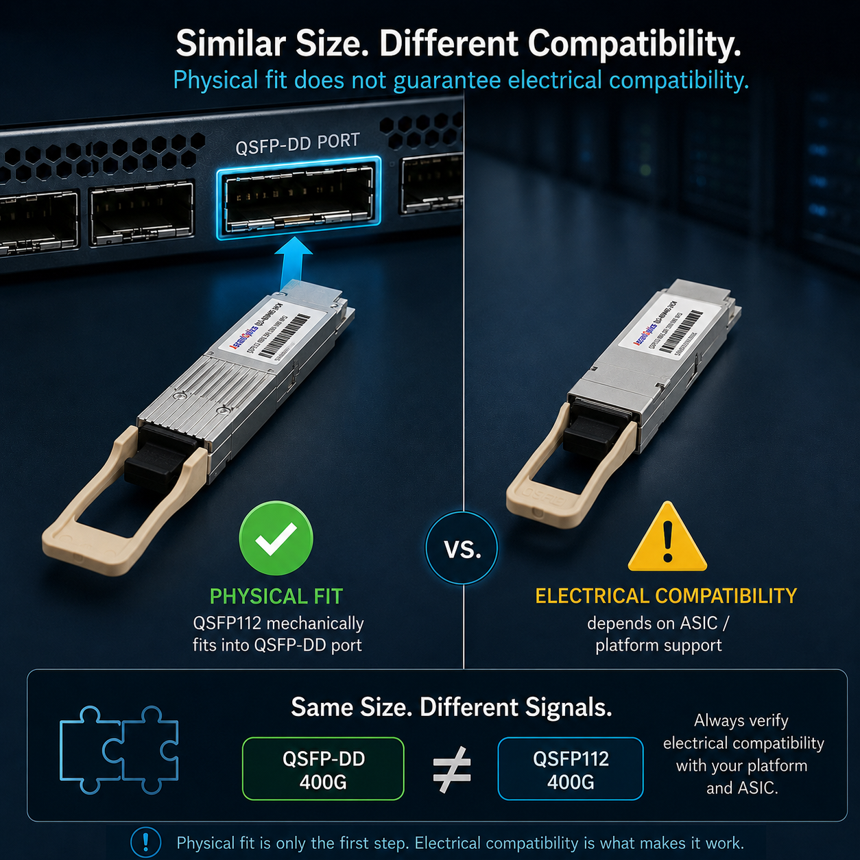
Can QSFP112 Plug Into a QSFP-DD Port?
Mechanically, a QSFP112 module may fit into a QSFP-DD cage designed for QSFP backward compatibility. Electrically, it works only when the host port explicitly supports the QSFP112 lane mode. A standard 400G QSFP-DD port wired and configured only for 8 x 50G PAM4 will not automatically support a 4 x 112G-class QSFP112 module.
Can QSFP28 Work in a QSFP112 Port?
Sometimes. A QSFP112-capable host may support lower-speed QSFP28 operation if the ASIC, port mode, firmware, and FEC configuration allow it. Never assume this from the cage shape alone. Confirm support in the platform datasheet or request a written compatibility statement from the switch or NIC vendor.
What to Verify Before Ordering
- •Host ASIC SerDes rate and lane count per port
- •Supported form factors and port operating modes
- •FEC requirements and breakout support
- •CMIS version and management features supported by host firmware
- •Vendor qualification list for the exact optic part number
Deployment Scenarios: Which Form Factor to Choose
The following decision framework moves beyond generic pros-and-cons lists. It matches infrastructure constraints to the form factor engineered for those conditions.
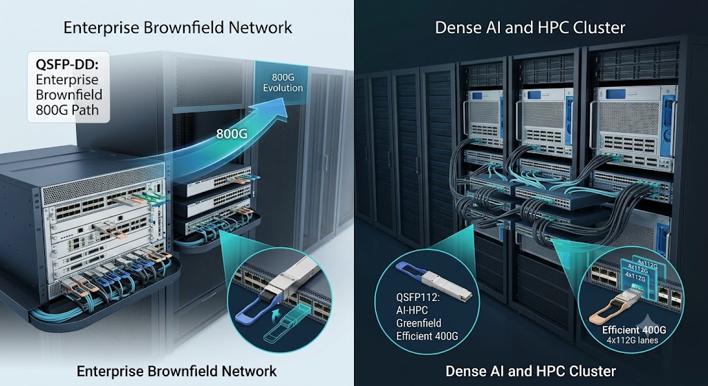
Choose QSFP-DD If Your Environment Matches These Criteria
Brownfield upgrades from QSFP28 or QSFP56.
If your data center already runs 100G or 200G infrastructure and you need to migrate gradually, QSFP-DD is the safer choice. You can insert legacy modules into the same ports while rolling out 400G in phases.
800G is on your three-to-five-year roadmap.
QSFP-DD800 modules are already in volume production. Investing in QSFP-DD switch platforms today protects your hardware investment when bandwidth requirements double.
Coherent optics for DCI or telecom applications.
QSFP-DD is the dominant form factor for 400G-ZR and ZR+ coherent pluggable modules used in metro and long-haul fiber optic communication.
Choose QSFP112 If Your Environment Matches These Criteria
NVIDIA-centric AI or HPC clusters.
NVIDIA standardized on QSFP112 for ConnectX-7 adapters, BlueField-3 DPUs, and Quantum-2 InfiniBand NDR switches. If your compute fabric is built around NVIDIA GPUs, QSFP112 is the native and optimized choice.
Power-constrained or thermally dense deployments.
The 15% to 25% per-module power savings of QSFP112 accumulate rapidly in high-density environments. Facilities approaching their rack power envelope can gain headroom by choosing the lower-wattage form factor.
Greenfield 400G with no legacy speed requirements.
If you are building new infrastructure from the ground up and every port will run at 400G, QSFP112 simplifies PCB design and reduces lane routing complexity.
Cost-sensitive procurement at scale.
QSFP112 modules are typically 15% to 30% less expensive than equivalent QSFP-DD variants. In deployments requiring thousands of units, that delta meaningfully impacts capital expenditure.
NVIDIA and AI/HPC Ecosystem: Use Precise Wording
AI and HPC deployments often include QSFP112, especially on some 400G NIC, HCA, and DPU options. However, it is inaccurate to describe every NVIDIA NDR switch platform as QSFP112. NVIDIA Quantum-2 1U switch systems use OSFP physical connectors, while adapters and DPUs may be offered with QSFP112 or OSFP depending on SKU.
For an article comparing form factors, the safer wording is: QSFP112 is widely used in 400G AI/HPC server-side connectivity and selected switch platforms, while OSFP and QSFP-DD also remain important in AI and high-density switching ecosystems. Always verify the exact platform and SKU.
The Hybrid Approach: Running Both in One Facility
Large facilities may run QSFP-DD in core, aggregation, or DCI layers while using QSFP112 in controlled 400G compute fabrics. This hybrid approach can work well, but it requires disciplined inventory control.
Because technicians may see similar module sizes and latches, label ports and optics clearly. Use separate bins, color-coded cable tags, and port-level documentation to reduce cross-installation risk. Operational process is part of compatibility management.
TCO at Scale: Power, Cost, and Rack Budget
TCO modeling should be based on your actual vendor quotes and module datasheets. The figures below are illustrative only and should not be presented as market-average pricing without a sourced pricing study.
Assume a 32-port 400G switch. If a QSFP-DD optic consumes 12W and a comparable QSFP112 optic consumes 10W, the optics-only power is 384W versus 320W, saving 64W per switch. Across 200 switches, this equals 12.8 kW of continuous IT power reduction.
Using $0.12/kWh and PUE 1.4, the annual facility-energy saving is approximately: 12.8 kW x 24 x 365 x $0.12 x 1.4 = $18,842 per year. Over three years, the energy-related saving is approximately $56,526. This model excludes demand charges, cooling design changes, labor, sparing, and downtime risk.
| Cost Component |
QSFP-DD Assumption
|
QSFP112 Assumption |
Illustrative Delta
|
| Module purchase price |
Use actual quote
|
Use actual quote |
Quote dependent
|
| Optics power per port |
12W example
|
10W example |
2W saved per port
|
| 32-port switch optics load |
384W
|
320W |
64W saved per switch
|
| 200-switch continuous IT power |
76.8 kW
|
64.0 kW |
12.8 kW saved
|
| Annual energy cost at $0.12/kWh, PUE 1.4 |
$113,054
|
$94,213 |
$18,842 saved
|
Migration Playbook: From QSFP28 to 400G
Pre-Migration Assessment
- •ASIC capability: verify electrical support, not just cage type. Confirm lane count, lane rate, and supported port modes.
- •Fiber plant inventory: confirm MMF/SMF type, connector type, polarity, insertion loss, and cleaning procedures. Existing fiber can often be reused, but 400G optics have tighter link budgets than many legacy 100G links.
- •Power and thermal budget: calculate incremental optics power, switch base power, fan behavior, rack PDU capacity, and cooling margin under worst-case ambient conditions.
- •Management interface: confirm that host firmware and NMS can read module presence, vendor data, DOM/DDM values, alarms, and firmware information through the required CMIS implementation.
- •Operational controls: update labels, spare-parts bins, cabling standards, and rollback documentation before production cutover.
Interoperability Testing in Mixed-Speed Environments
- •Run a pilot on four to eight ports before full-scale rollout.
- •Monitor link stability for at least 72 hours under realistic traffic and temperature conditions.
- •Check pre-FEC and post-FEC error counters, corrected codeword trends, and any FEC mismatch alarms.
- •Validate DOM/DDM reporting in the switch CLI and NMS.
- •Confirm rollback from 400G to the previous 100G configuration before touching large batches of ports.
Cable Reuse vs Replacement Strategy
Existing 100G DAC and AOC assemblies generally cannot be reused for 400G because their electrical or optical design is specific to the original lane rate and module type. Budget for new 400G-rated DAC, AOC, or optical transceiver assemblies.
Fiber patch cords and trunks may be reusable if the fiber type, connector, polarity, and loss budget match the selected 400G optic. OM4 can support many 400G SR4 deployments up to 100 meters, while OS2 single-mode fiber supports DR4, FR4, LR4, and coherent variants according to module specifications. Clean and test connectors before blaming optics.
Rollback Planning
Before cutover, document the original 100G module part number, firmware, switch port configuration, FEC settings, VLAN or routing configuration, and patch-panel position. Store removed QSFP28 modules in antistatic packaging with location labels. A clear rollback path turns a failed 400G activation from a multi-hour incident into a controlled maintenance step.
Conclusion
The QSFP-DD vs QSFP112 decision is not a simple choice between old and new. QSFP-DD offers a broader compatibility and roadmap story, especially for brownfield networks, mixed-speed migration, DCI/coherent optics, and future 800G planning. QSFP112 offers an efficient 4-lane 400G architecture that can be attractive in power-sensitive, greenfield, and AI/HPC-oriented deployments.
Choose QSFP-DD when backward compatibility, multi-vendor flexibility, and an 800G roadmap matter more than a potential per-module power saving. Choose QSFP112 when the host platform is designed for 112G-class PAM4, every relevant link is intended for 400G operation, and rack power or module cost is a major constraint.
Whichever direction your evaluation points, verify ASIC compatibility before placing orders. Physical fit is not enough. The electrical interface is what determines whether your optical transceiver module links up or sits dark.
Ready to evaluate QSFP112 transceivers for your network? Contact our optical networking experts to discuss compatibility, module selection, and custom optical solutions for your data center or AI cluster deployment.
Frequently Asked Questions
The following FAQ addresses the most common procurement and deployment questions engineers ask when comparing QSFP112 and QSFP-DD for 400G networks.
Is QSFP112 better than QSFP-DD for 400G networks?
Not universally. QSFP112 can be a strong choice for greenfield 400G deployments where the host platform is designed for 112G-class PAM4 lanes and power efficiency is important. QSFP-DD is usually the safer choice when backward compatibility, multi-vendor flexibility, coherent optics, or a smoother 800G roadmap matter more.
Can a QSFP112 module work in a QSFP-DD port?
Mechanical fit alone is not enough. A QSFP112 module may fit in some QSFP-DD cages that support QSFP-family modules, but the host ASIC, port wiring, firmware, and port mode must support the 4-lane 112G-class PAM4 interface. Always verify the exact switch or NIC datasheet before ordering.
Can a QSFP-DD module work in a QSFP112 port?
In most cases, no. A 400G QSFP-DD module normally expects an 8-lane 50G-class PAM4 host electrical interface, while QSFP112 expects a 4-lane 112G-class PAM4 interface. Unless the host platform explicitly supports both modes, the module will not link up.
Is QSFP112 backward compatible with QSFP28?
Sometimes, but it is host dependent. Some QSFP112-capable ports may support lower-speed QSFP28 operation through firmware and port-mode configuration. Other platforms are fixed for 400G operation and will not recognize 100G QSFP28 modules. Do not assume compatibility based on the cage size.
Does QSFP112 support 800G upgrades?
QSFP112 should be treated as a 400G form factor. It does not provide a native 800G upgrade path in the same way that QSFP-DD can evolve to QSFP-DD800. If 800G is part of the next network refresh, evaluate QSFP-DD800, OSFP, or other 800G-ready platforms early in the design process.
Which form factor is better for AI and HPC clusters?
QSFP112 is common in 400G AI and HPC environments, especially on platforms that use 112G-class SerDes and prioritize high port density and power efficiency. However, the exact choice depends on the NIC, DPU, switch platform, cable reach, and vendor qualification list. Avoid describing the entire AI ecosystem as QSFP112-only.
Which form factor has lower power consumption?
QSFP112 often has a power advantage for comparable 400G client optics because it uses fewer host electrical lanes. However, power varies by reach, DSP design, temperature range, optical variant, and vendor implementation. Compare actual datasheets for the same reach type before building a power budget.
Can existing QSFP28 fiber cabling be reused for 400G?
Often yes for fiber patch cords and trunks, but not for 100G DAC or AOC assemblies. OM4 multimode fiber may support 400G-SR4 within the specified distance and loss budget, while OS2 single-mode fiber can support DR4, FR4, LR4, or coherent options depending on the optical module. Connector cleanliness, polarity, and insertion loss must be revalidated.
What should procurement verify before buying QSFP112 or QSFP-DD modules?
Procurement should verify the host port form factor, ASIC SerDes lane rate, lane count, supported FEC mode, CMIS version, firmware version, vendor qualification list, power class, thermal requirements, and intended fiber type. The part number should be approved for the exact switch, NIC, or DPU model.
Post Views: 1,016