If you are evaluating 400G optical transceiver options for a data center upgrade, you have probably encountered the same question: What is QSFP112, and how does it compare to QSFP-DD or OSFP? The answer matters because choosing the wrong form factor can lock you into higher power bills, incompatible switch ports, or a dead-end upgrade path.
This guide explains what QSFP112 is, how it works, and when to deploy it in your optical networking infrastructure. You will learn the technical specifications, the available transceiver types, compatibility considerations, and practical deployment guidance based on real network engineering scenarios.
What Is QSFP112?
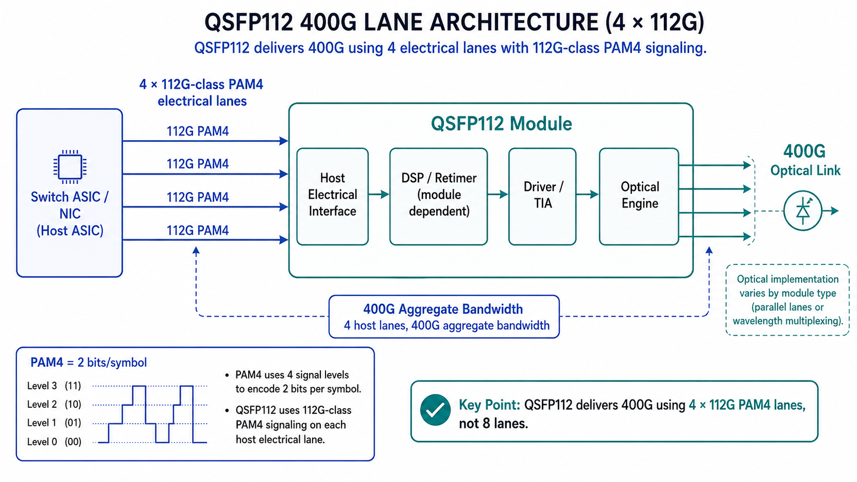
QSFP112 (Quad Small Form-factor Pluggable 112) is a hot-pluggable optical transceiver module that delivers 400 Gbps of aggregate bandwidth using four electrical lanes operating at 112 Gbps per lane with PAM4 signaling. It maintains the same physical dimensions as the QSFP28 and QSFP56 form factors, which allows data centers to upgrade bandwidth density without replacing switch cages or physical fiber infrastructure.
QSFP112 Naming and Standards
The “112” in QSFP112 refers to the 112 Gbps data transmission rate per electrical lane. This distinguishes it from earlier generations: QSFP28 uses 4 x 25 Gbps lanes, and QSFP56 uses 4 x 56 Gbps lanes. QSFP112 doubles the per-lane rate again to reach 400 Gbps total in the same compact package.
QSFP112 modules comply with several industry standards that ensure interoperability across vendors:
- •QSFP112 MSA defines the mechanical, electrical, and thermal specifications for the module form factor
- •IEEE 802.3ck governs 100 Gbps and 400 Gbps Ethernet electrical interfaces using 112G PAM4 signaling
- •IEEE 802.3bs and IEEE 802.3cm define 400G Ethernet optical interfaces over multimode and single-mode fiber.
- •IEEE 802.3cu defines 400 Gbps Ethernet over single-mode fiber for 2 km and 10 km reaches
- •OIF-CEI-112G-VSR-PAM4 sets the electrical channel requirements for very-short-reach chip-to-module links
- •CMIS 5.0/5.2 provides the common management interface specification for module firmware and diagnostics
How QSFP112 Works
Inside a QSFP112 optical transceiver module, four electrical lanes carry 112 Gbps each using PAM4 (Pulse Amplitude Modulation 4-level) signaling. PAM4 encodes two bits per symbol by using four distinct voltage levels, which doubles the throughput at the same baud rate compared to traditional NRZ (Non-Return-to-Zero) signaling.
This higher signaling complexity requires advanced signal processing. Each QSFP112 module contains:
- •DSP (Digital Signal Processing) chips that equalize and precondition the electrical signal
- •CDR (Clock and Data Recovery) circuits that lock onto the incoming data stream and remove jitter
- •FEC (Forward Error Correction) engines that detect and correct bit errors caused by noise at these high data rates
The optical engine then modulates the corrected electrical signals onto laser carriers for transmission over fiber optic cable. On the receive side, the process reverses: photodetectors convert optical signals back to electrical, and the DSP/CDR/FEC chain recovers the original data.
QSFP112 Technical Specifications
Electrical Interface and Signaling
The QSFP112 electrical interface operates at 112 Gbps per lane using PAM4 modulation. This represents a significant leap from the 25 Gbps NRZ signaling used in QSFP28 modules. The electrical specifications follow the OIF-CEI-112G-VSR-PAM4 standard, which defines the channel loss budgets, crosstalk limits, and jitter tolerances required for reliable operation.
Because PAM4 signals are more susceptible to noise than NRZ, FEC is mandatory for QSFP112 links. Most 400G Ethernet implementations use Reed-Solomon FEC (RS-FEC, RS(544,514)) as defined in IEEE 802.3. RS-FEC introduces additional latency, typically in the hundreds of nanoseconds range depending on the switch ASIC and implementation.Some high-performance computing environments may use lighter FEC modes or even firecode FEC if the channel quality supports it, though this requires careful validation.
Power Consumption and Thermal Design
QSFP112 optical transceiver modules typically consume 8 to 12 watts per module, depending on the optical variant and reach. Short-reach multimode modules such as SR4 tend toward the lower end of this range, while long-reach single-mode modules with complex DSP such as LR4 may approach the upper limit.
This power consumption is roughly 30 percent lower per module than equivalent QSFP-DD 400G modules, which typically draw 10 to 14 watts. For a 32-port 400G switch fully populated with QSFP112 modules, the power savings can reach 64 to 128 watts of optical power alone. In dense data center racks where every watt translates to cooling load, this difference directly affects operational expenditure.
QSFP112 modules use a flat-top thermal design that maximizes contact area with the switch heatsink. The module case temperature must remain within the MSA-specified range, typically 0 to 70 degrees Celsius for commercial-grade units. Data center operators should verify that their switch platforms provide adequate airflow across the QSFP112 cage array, especially in fully loaded 1RU chassis.
Physical Dimensions and Port Density
The QSFP112 form factor maintains the same physical envelope as QSFP28: approximately 18.4 mm wide, 89.4 mm long, and 8.5 mm high. This dimensional consistency is deliberate. It allows network equipment vendors to design 400G switches that reuse the same front-panel cage and PCB keepout areas as their 100G predecessors.
In practice, this means a 1RU switch can house up to 32 QSFP112 ports, delivering 12.8 Tbps of switching capacity in a single rack unit. This port density is essential for hyperscale data centers that need to maximize bandwidth per square meter of floor space.
Types of QSFP112 Optical Transceivers
QSFP112 optical transceiver modules are available in several variants optimized for different transmission distances and fiber types. Selecting the correct type depends on your link budget, fiber infrastructure, and connector compatibility.
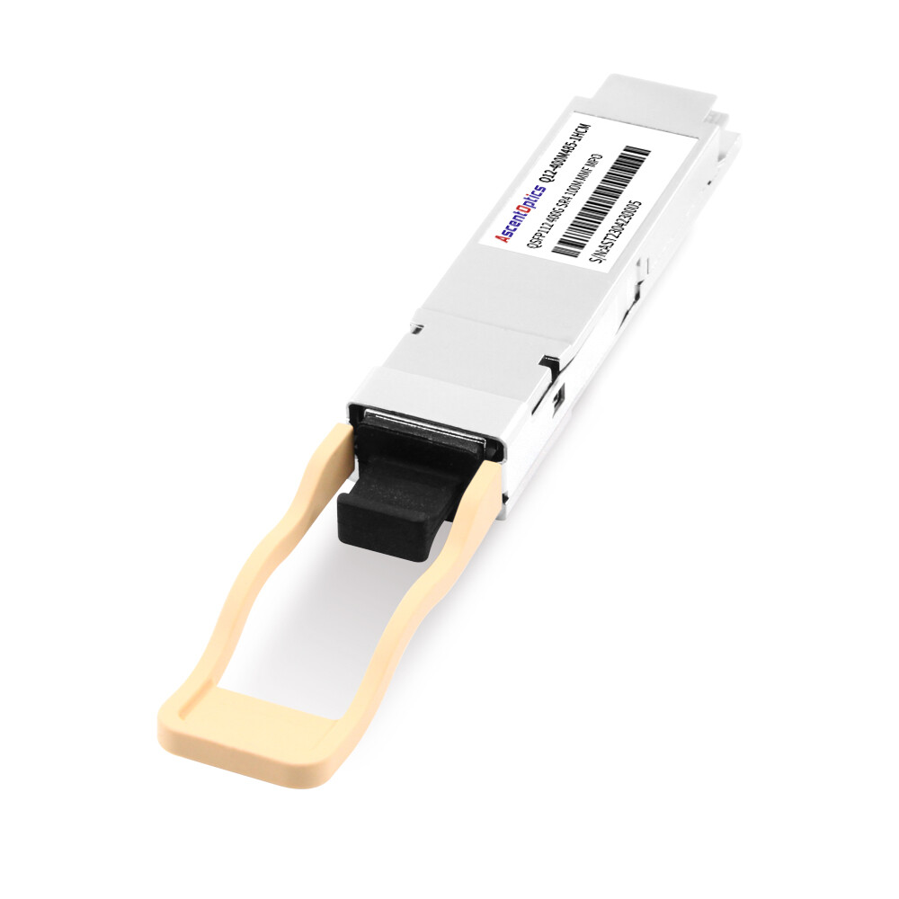
Multimode Fiber Variants (VR4 / SR4)
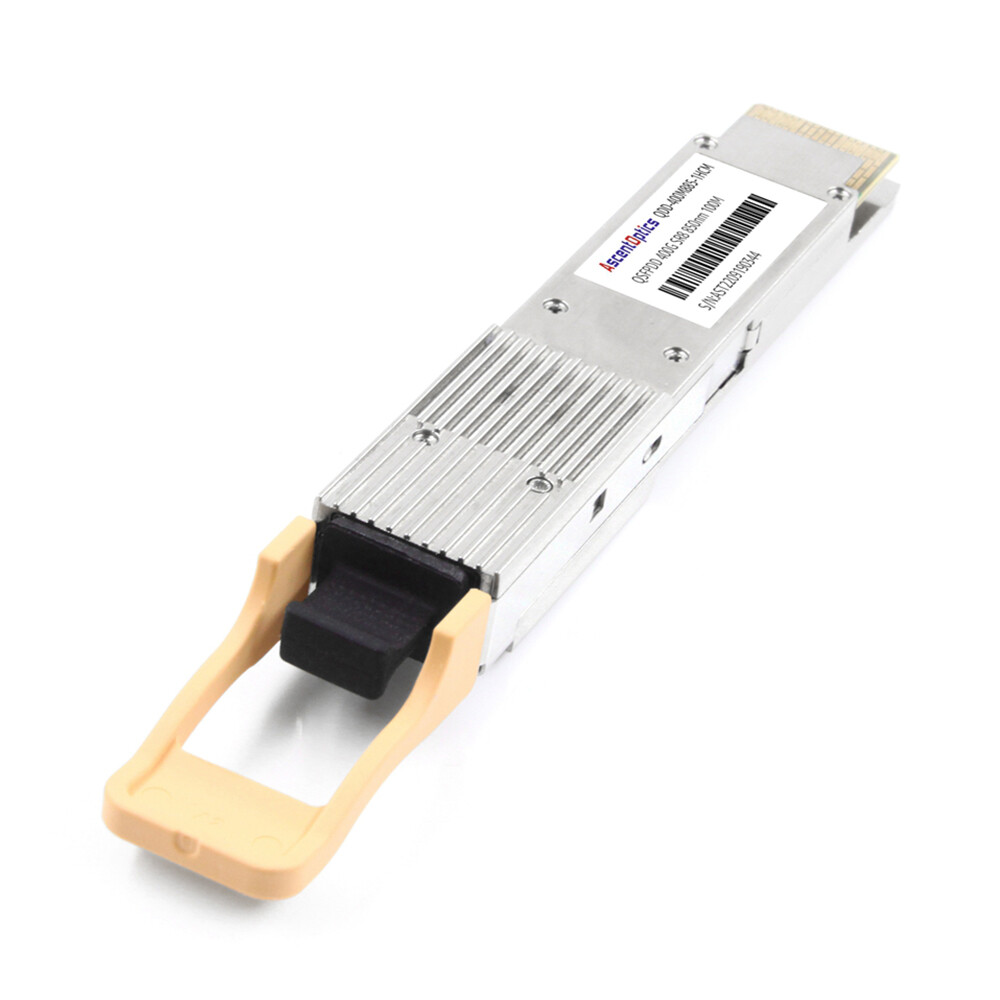
For short-reach connections inside data centers, QSFP112 VR4 and SR4 modules transmit over multimode fiber (MMF) using 850 nm vertical-cavity surface-emitting lasers (VCSELs).
- •QSFP112-VR4: Supports up to 50 meters over OM4 multimode fiber
- •QSFP112-SR4: Supports up to 100 meters over OM4 multimode fiber
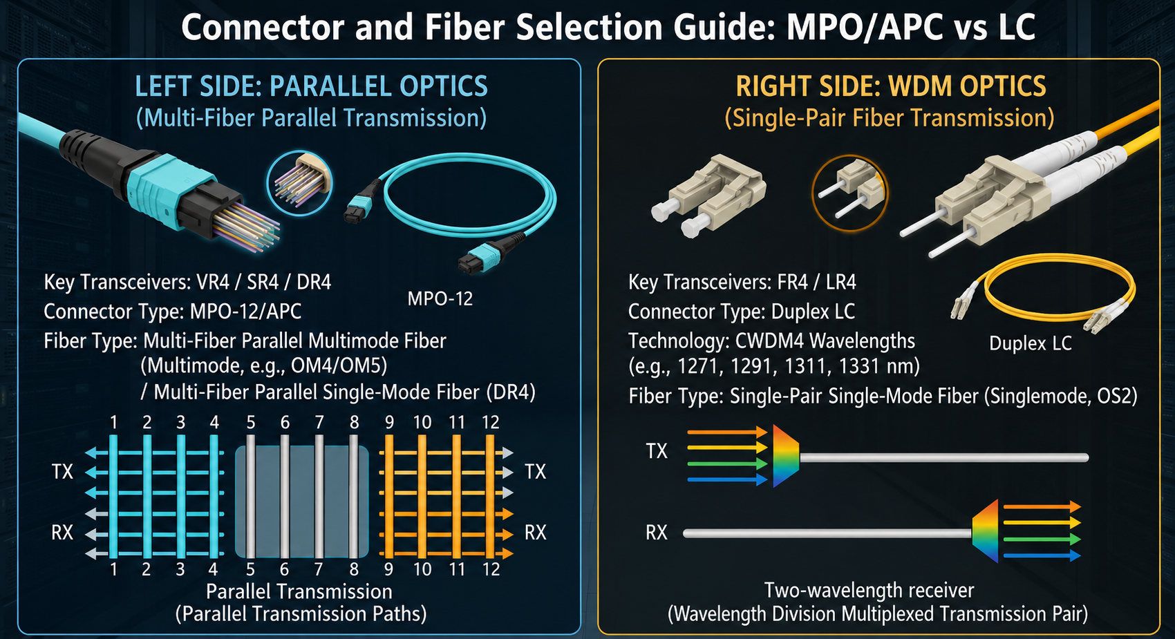
Both variants use an MPO-12/APC (Angled Physical Contact) connector. The APC polish is critical because flat-polished MPO connectors can reflect light back into the transmitter, causing signal degradation at these power levels. The twelve-fiber MPO ribbon cable carries four transmit and four receive fibers, with four fibers remaining unused.
These modules are ideal for intra-rack and adjacent-rack connections in data centers where the switch and server or storage arrays are within the same row.
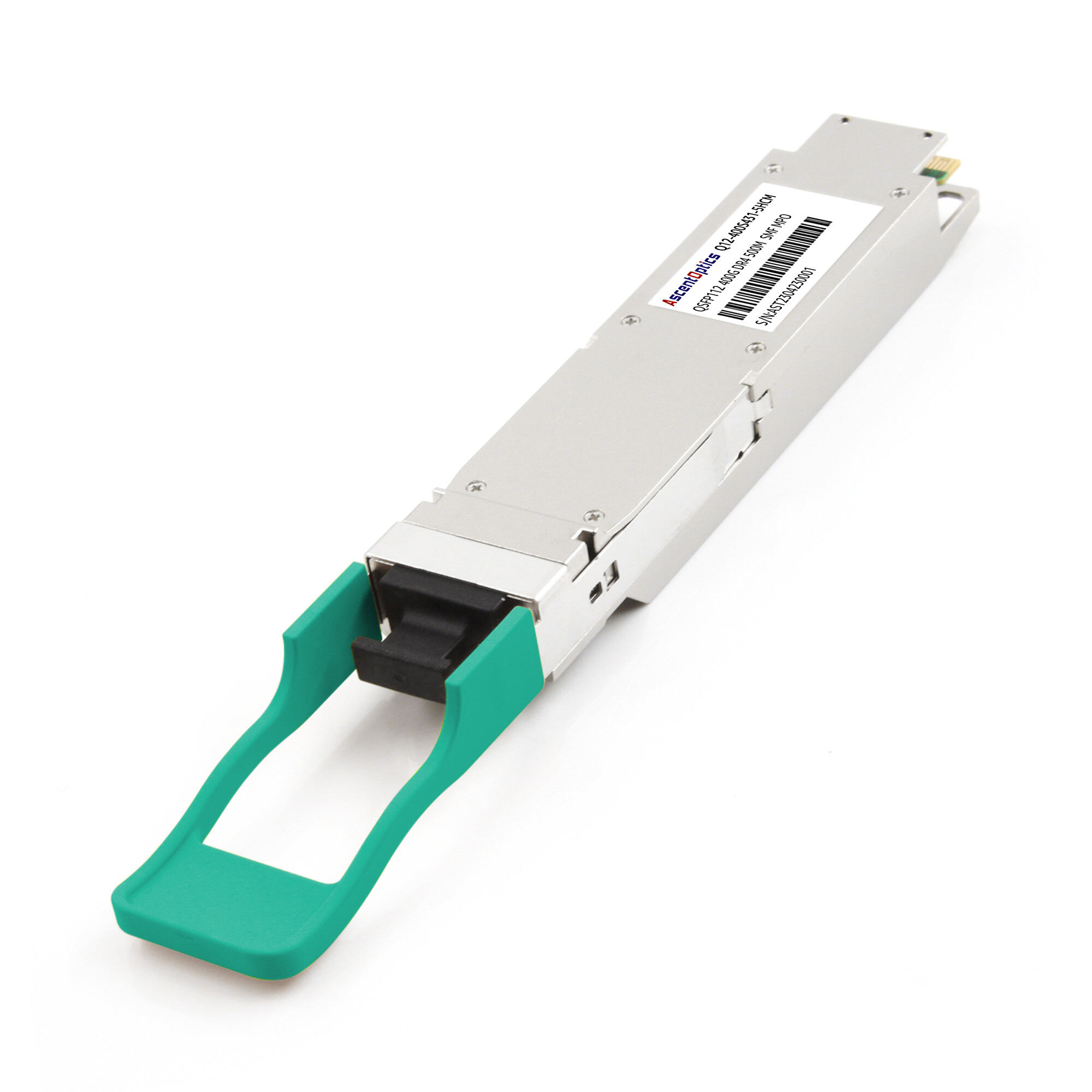
Single-Mode Fiber Variants (DR4 / FR4 / LR4)
For longer reaches and data center interconnect applications, single-mode fiber (SMF) variants typically use four parallel 1310nm optical lanes implemented through EML or silicon photonics technologies.
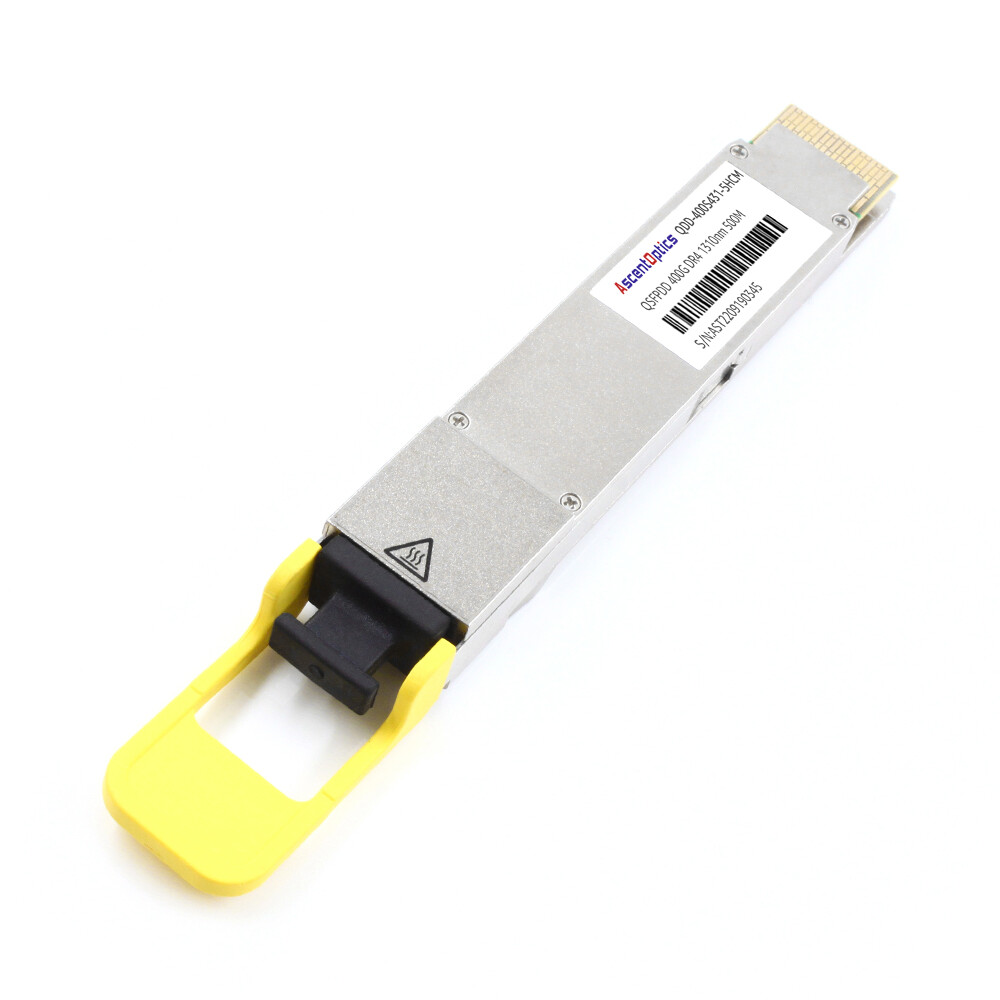
- •QSFP112-DR4: Supports 500 meters over single-mode fiber using an MPO-12/APC connector. This variant uses four parallel single-mode lanes and is commonly deployed in campus-style data center environments.
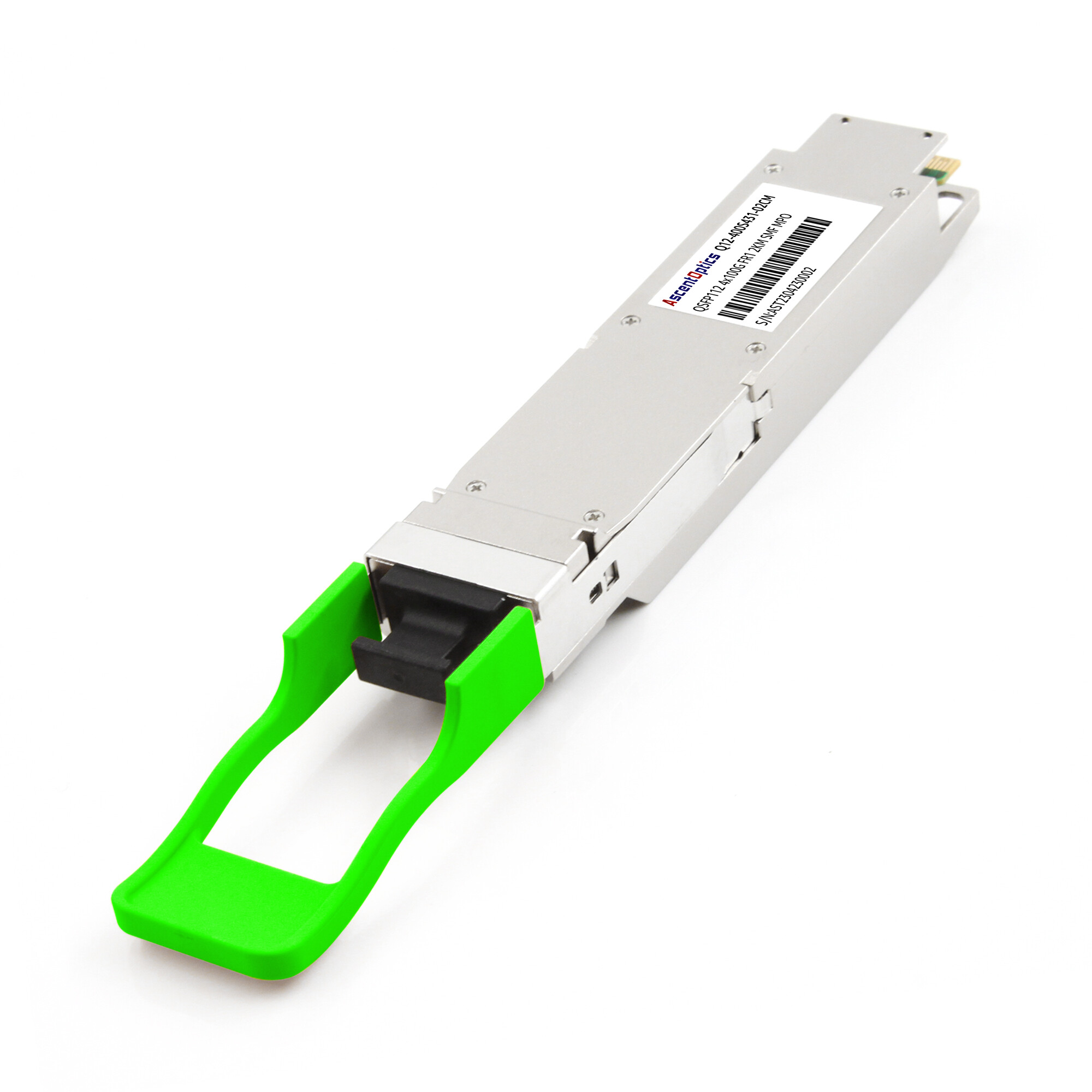
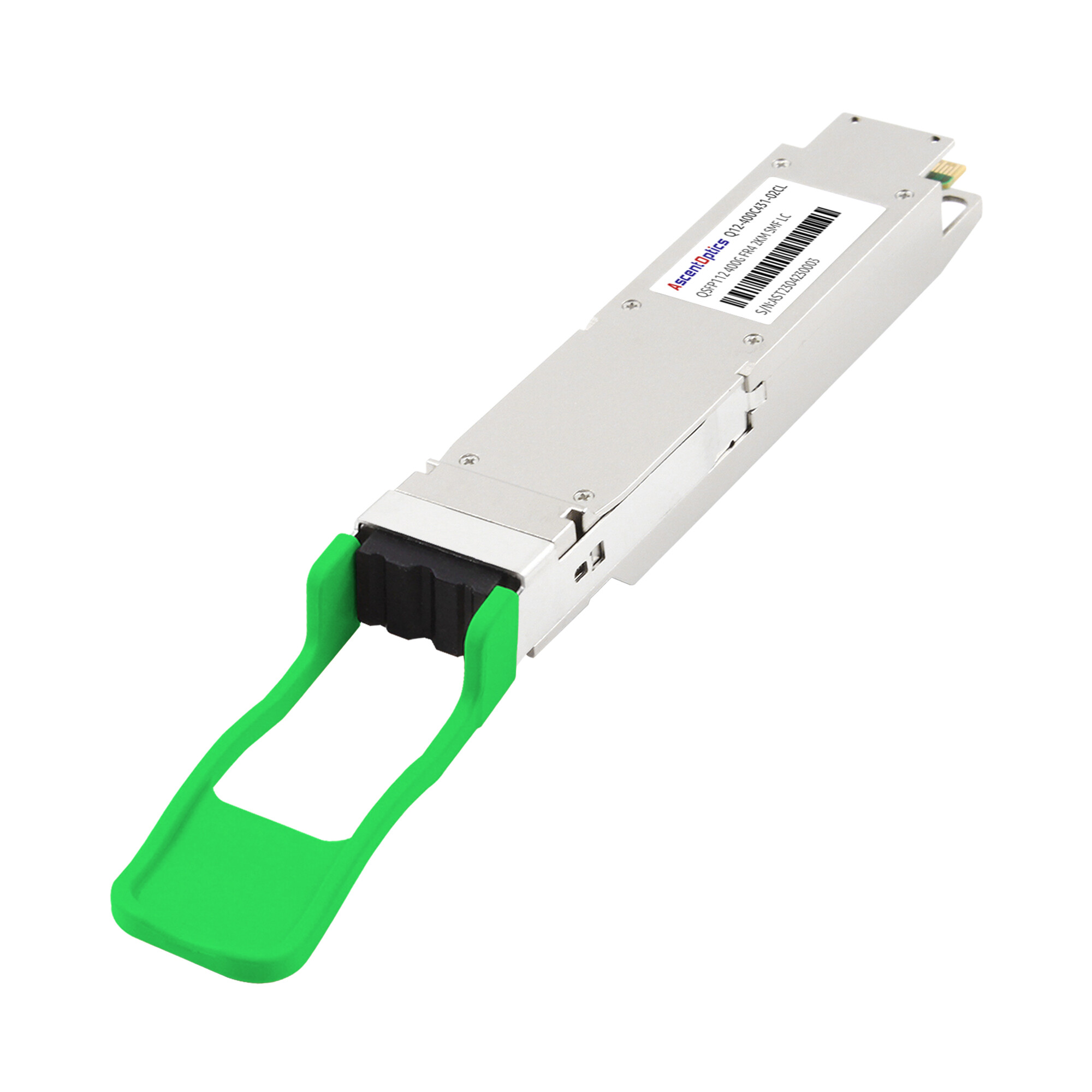
- •QSFP112-FR4: Supports 2 kilometers over single-mode fiber using a duplex LC connector. FR4 modules multiplex four wavelengths (around 1271 nm, 1291 nm, 1311 nm, and 1331 nm) onto a single fiber pair using CWDM4 technology. This reduces fiber count compared to DR4.
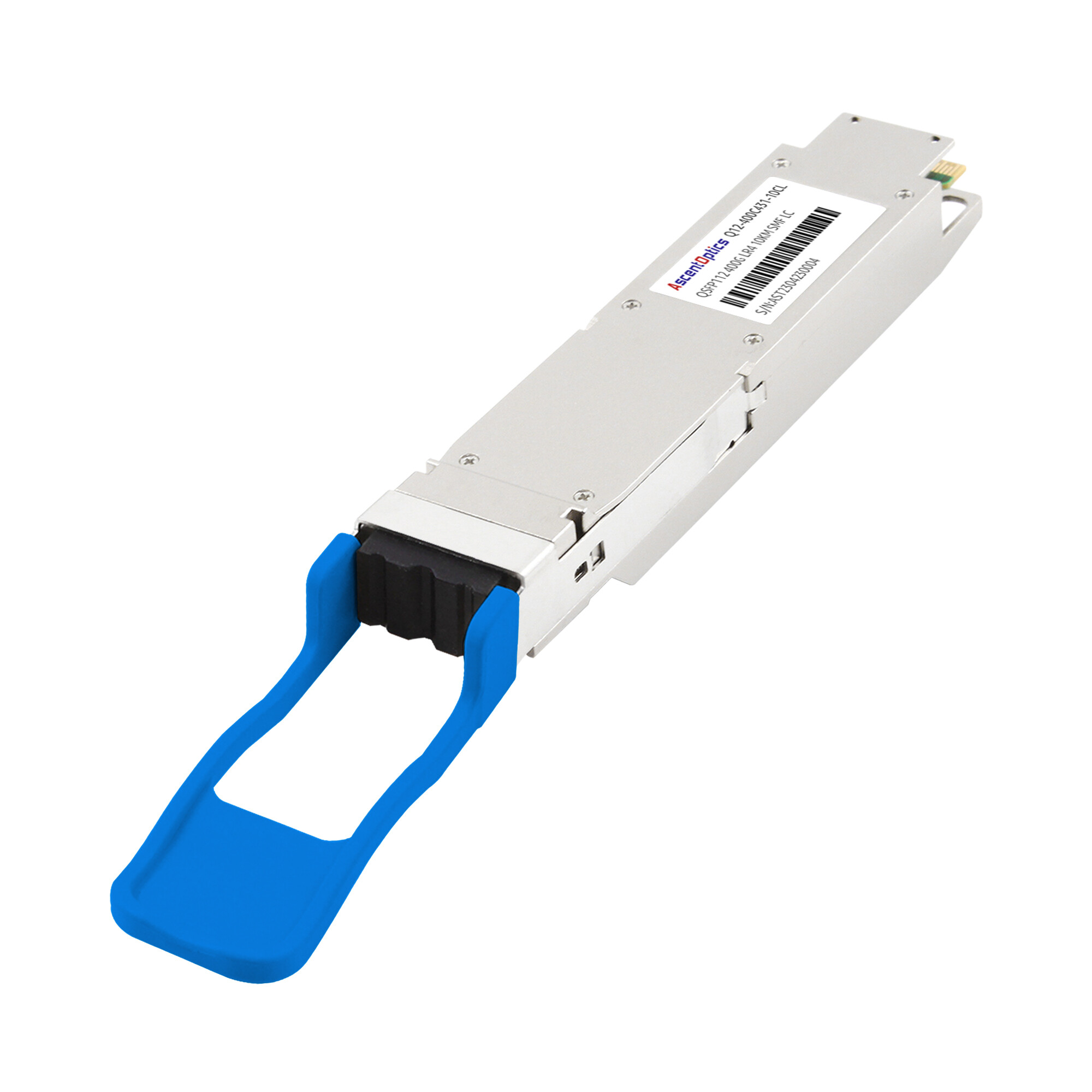
- •QSFP112-LR4: Supports 10 kilometers over single-mode fiber using a duplex LC connector. LR4 modules also use CWDM4 wavelength multiplexing but include stronger FEC and higher-output optical components to achieve the extended reach.
Connector and Fiber Infrastructure Requirements
Deploying QSFP112 modules requires attention to connector and fiber compatibility. Here is a quick checklist for network engineers:
- •MPO-12/APC connectorsare required for VR4, SR4, and DR4 variants. Verify that your existing fiber plant uses APC-polished MPO connectors, not UPC (Ultra Physical Contact), which can cause excessive reflectance.
- •Duplex LC connectorsare used for FR4 and LR4 variants. Standard single-mode patch cables with LC connectors are sufficient.
- •Fiber type: MMF variants require OM4 or OM5 multimode fiber. SMF variants require OS2 single-mode fiber.
- •Cable bend radius: High-density patching in 1RU switches can stress fiber cables. Use bend-insensitive fiber where cable management space is limited.
Connector type verification should be part of every 400G deployment plan, as MPO polarity and connector polish mismatches can significantly delay installation.
QSFP112 vs. QSFP-DD vs. OSFP: How to Choose
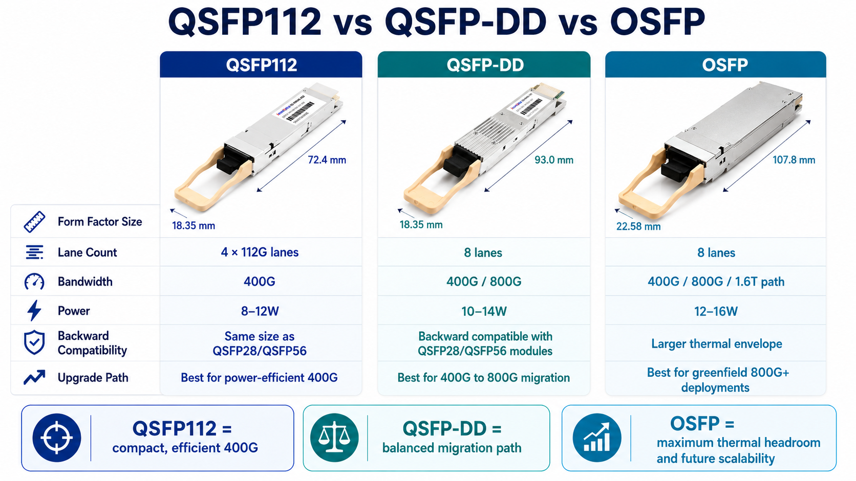
Network engineers evaluating 400G optical transceiver options must choose between three primary form factors: QSFP112, QSFP-DD, and OSFP. Each has distinct trade-offs in power, density, backward compatibility, and upgrade path.
| Specification |
QSFP112
|
QSFP-DD |
OSFP
|
| Electrical lanes |
4 x 112 Gbps
|
8 × 50G or 4 × 100G |
8 x 50 Gbps or 8 x 100 Gbps
|
| Aggregate bandwidth |
400 Gbps
|
400 Gbps / 800 Gbps |
400 Gbps / 800 Gbps / 1.6 Tbps
|
| Form factor size |
Same as QSFP28
|
Slightly deeper than QSFP28 |
Larger than QSFP28
|
| Typical power |
8 – 12W
|
10 – 14W |
12 – 16W
|
| Backward compatibility |
QSFP28/QSFP56 cages
|
QSFP28/QSFP56 cages |
Requires an adapter for QSFP28
|
| 800G upgrade path |
No
|
Yes |
Yes
|
| Best use case |
Power-sensitive 400G, AI/HPC
|
Enterprise 400G/800G migration |
Greenfield 800G+ deployments
|
When to Choose QSFP112
QSFP112 optical transceiver modules excel in scenarios where power efficiency and physical compatibility with existing QSFP infrastructure are priorities. Choose QSFP112 when:
- •Your switch ASICs support 112G PAM4 electrical lanes (for example, NVIDIA ConnectX-7, certain Arista 7500R3 line cards)
- •You need 400G connectivity today and do not require an 800G upgrade path on the same hardware generation
- •Power and thermal budgets are constrained, such as in dense AI server racks, where GPU power already dominates the thermal envelope
- •You want to reuse existing QSFP28 fiber cabling and patch panels without infrastructure changes
When to Choose QSFP-DD or OSFP
QSFP-DD and OSFP are better choices when future-proofing for 800G is a requirement. QSFP-DD achieves 400G using eight 50G lanes and can scale to 800G using eight 100G lanes. OSFP offers the largest thermal envelope and is the preferred form factor for 800G and 1.6 Tbps switch platforms.
Choose QSFP-DD when you need backward compatibility with QSFP28 modules in a mixed 100G/400G/800G environment. Choose OSFP for new greenfield data centers where maximum thermal headroom and the longest upgrade path are priorities.
For a detailed comparison, see our QSFP-DD vs QSFP112 guide.
QSFP112 Deployment Considerations
Switch ASIC and Port Compatibility
The most common misunderstanding about QSFP112 involves backward compatibility. While a QSFP112 module physically fits into a QSFP28 cage, it will not function unless the host switch ASIC supports 112G PAM4 electrical signaling. The physical dimensions are identical, but the electrical interface is fundamentally different.
Conversely, a QSFP28 100G module can typically operate in a QSFP112 port, but the port will negotiate down to 100G. This allows gradual migration: you can install QSFP112-capable switches today and populate them with QSFP28 modules, then upgrade to QSFP112 modules as bandwidth demands grow.
Before procurement, verify your switch datasheet for 112G SerDes support. Major platforms with QSFP112 support include:
- •NVIDIA ConnectX-7 adapters and Quantum-2 NDR switches
- •Select Arista 7500R3 and 7060X5 series switches
- •Certain Cisco 8000 series routers
- •Supermicro and other white-box switch platforms based on 112G-capable silicon
Signal Integrity and FEC Planning
At 112 Gbps per lane, signal integrity becomes a critical design consideration. PAM4 signaling has a lower signal-to-noise margin than NRZ, which means channel loss, crosstalk, and reflections have a larger impact on bit error rates.
In practice, this means the PCB traces inside the switch, the connector quality, and the cable assembly all matter more than at lower speeds. IEEE 802.3ck defines channel insertion loss budgets that switch designers must meet. As a network operator, you should ensure that your DAC (Direct Attach Copper) or AOC (Active Optical Cable) assemblies are rated for 112G PAM4 operation if you use cable-based interconnects instead of fiber transceivers.
FEC mode selection also affects latency. RS-FEC (544,514) adds approximately 2.3 microseconds of round-trip latency. For most data center switching applications, this is negligible. However, in ultra-low-latency financial trading or certain HPC collectives, engineers may evaluate whether lighter FEC or direct-attached copper alternatives are preferable.
Thermal and Power Budgeting
When planning a QSFP112 deployment, calculate the total power budget carefully. A fully loaded 32-port 400G switch with QSFP112 modules can consume 256 to 384 watts of optical power alone, plus the switch ASIC and fan power.
Data center operators should verify that their rack power distribution units and cooling systems can handle the load. For facilities approaching power limits, QSFP112’s lower per-module consumption compared to QSFP-DD can be the deciding factor that allows 400G deployment without electrical infrastructure upgrades.
QSFP112 Applications in Modern Networks
QSFP112 optical transceiver modules are deployed across several high-bandwidth networking scenarios where 400G density and power efficiency matter.
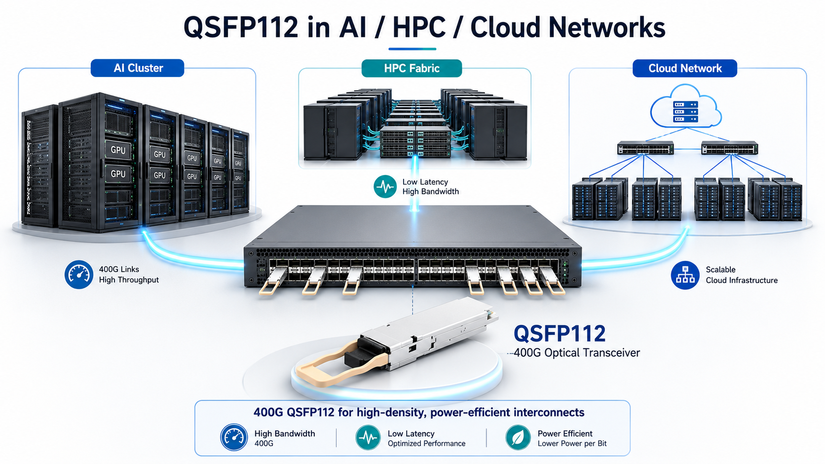
1. Hyperscale data center leaf-spine fabrics use QSFP112 to interconnect top-of-rack switches to spine layers. The ability to deliver 400G per port in a QSFP28-compatible footprint allows hyperscale operators to upgrade bandwidth without forklift-switch replacements.
2. AI and machine learning training clusters benefit from QSFP112’s power efficiency. In dense GPU racks where each server node draws thousands of watts, saving even a few watts per optical port reduces total rack power and cooling requirements. NVIDIA’s ConnectX-7 adapters and NDR InfiniBand switches commonly use QSFP112 for GPU-to-GPU and GPU-to-storage interconnects.
Modern AI clusters frequently adopt rail-optimized network architectures built around 400G Ethernet or InfiniBand fabrics. QSFP112 aligns naturally with these environments because it supports native 4×100G breakout configurations and integrates with current-generation 112G SerDes switch ASICs and network adapters.
3. High-performance computing environments deploy QSFP112 for MPI (Message Passing Interface) networks where bandwidth and latency directly affect simulation throughput. The 400G line rate supports modern fat-tree and dragonfly topologies without port oversubscription.
4. Cloud provider backbone networks use QSFP112 FR4 and LR4 variants for data center interconnect links up to 2 km and 10 km. The duplex LC connector on CWDM variants simplifies fiber management compared to parallel MPO solutions.
5. Edge data center aggregation represents an emerging use case. As edge facilities consolidate traffic from 5G base stations and IoT gateways, they need higher uplink bandwidth. QSFP112 provides a compact, cost-effective 400G aggregation option for space-constrained edge locations.
Conclusion
QSFP112 represents an important step in the evolution of 400G networking. By combining a native 4×112G PAM4 electrical architecture with the familiar QSFP form factor, it enables data centers to achieve higher bandwidth density while maintaining operational efficiency. As modern switch ASICs and network adapters increasingly adopt 112G SerDes technology, QSFP112 has become a practical solution for high-performance Ethernet and InfiniBand deployments.
For organizations building AI clusters, HPC environments, and next-generation leaf-spine fabrics, QSFP112 offers a compelling balance of performance, power efficiency, and deployment simplicity. Whether deploying short-reach SR4 links inside a data hall or using DR4, FR4, and LR4 optics for larger-scale infrastructures, selecting the right QSFP112 transceiver can help optimize both network scalability and total cost of ownership.
Before deployment, network engineers should carefully evaluate switch compatibility, fiber infrastructure, connector requirements, thermal capacity, and future bandwidth plans. While QSFP-DD and OSFP may provide a clearer migration path to 800G networking, QSFP112 remains one of the most efficient and widely adopted options for organizations focused on high-density 400G connectivity today.
As AI workloads, cloud services, and data-intensive applications continue to drive network growth, QSFP112 is expected to play a significant role in supporting the next generation of data center infrastructure.
Frequently Asked Questions
Q1: Is QSFP112 backward compatible with QSFP28?
A: Physically, yes. A QSFP112 module fits into a QSFP28 cage. Electrically, it depends on the host port. A QSFP112 module requires a switch port that supports 112G PAM4 signaling. A QSFP28 module can operate in a QSFP112 port at 100G, but a QSFP112 module will not function in a QSFP28-only port.
Q2: Can QSFP112 support 800G?
A: No. QSFP112 is limited to 400G because it uses four lanes at 112 Gbps each, and the QSFP form factor cannot accommodate more than four lanes. For 800G, you need an eight-lane form factor such as QSFP-DD or OSFP.
Q3: What is the difference between QSFP112 and QSFP-DD?
A: QSFP112 delivers 400G using four lanes at 112 Gbps in the standard QSFP form factor. QSFP-DD delivers 400G using eight lanes at 50 Gbps in a slightly deeper form factor. QSFP-DD can upgrade to 800G by doubling lane speed, while QSFP112 cannot. QSFP112 consumes less power but has a narrower vendor ecosystem.
Q4: How much power does QSFP112 consume?
Typical QSFP112 optical transceiver modules consume 8 to 12 watts, with short-reach multimode variants at the lower end and long-reach single-mode variants at the higher end. This is approximately 30 percent less than equivalent QSFP-DD modules.
Q5: What fiber cable do I need for QSFP112?
For VR4 and SR4 variants, use OM4 or OM5 multimode fiber with MPO-12/APC connectors. For DR4, use OS2 single-mode fiber with MPO-12/APC connectors. For FR4 and LR4, use OS2 single-mode fiber with duplex LC connectors.
Q6: Is QSFP112 replacing QSFP-DD?
No. QSFP112 and QSFP-DD serve different market segments. QSFP112 is primarily optimized for high-density 400G deployments based on 112G electrical lanes, while QSFP-DD remains the dominant form factor for environments requiring backward compatibility and migration to 800G Ethernet.
Post Views: 1,054