In 2026, a single hyperscale AI data center can consume more than 800G optical transceivers than the entire industry shipped just three years ago. That demand is reshaping how network engineers think about QSFP data center connectivity. The QSFP form factor, once synonymous with 40G aggregation, now spans 100G, 400G, and 800G deployments. Choosing the wrong module for a spine-leaf link or a data center interconnect can strand fiber, waste power, and delay a capacity upgrade by quarters.
What Is a QSFP Module in a Data Center?
A QSFP module is a compact, hot-pluggable optical transceiver that transmits and receives data over fiber optic cable. QSFP stands for Quad Small Form-Factor Pluggable. The “quad” refers to the four transmit and four receive lanes that give the module its bandwidth. Today, QSFP-based modules span data rates from 40G to 800G, with 800G QSFP-DD becoming widely deployed in AI clusters, cloud data centers, and hyperscale networks.
In a data center, QSFP modules plug into switches, routers, and network interface cards. They convert electrical signals from the host device into optical signals for transmission across fiber. Because they are hot-pluggable, engineers can install or replace them without powering down the switch, which reduces maintenance windows and simplifies upgrades.
QSFP modules follow Multi-Source Agreement (MSA) standards. MSA compliance means modules from different vendors share the same physical dimensions, electrical interface, and management protocol. That interoperability is critical in mixed-vendor environments where switch hardware may come from one supplier and optics from another.
QSFP Form Factor Evolution: From QSFP+ to QSFP-DD800
The QSFP family has evolved through several generations. Each generation increased lane speed or lane count to reach higher aggregate bandwidth without radically changing the physical cage size.
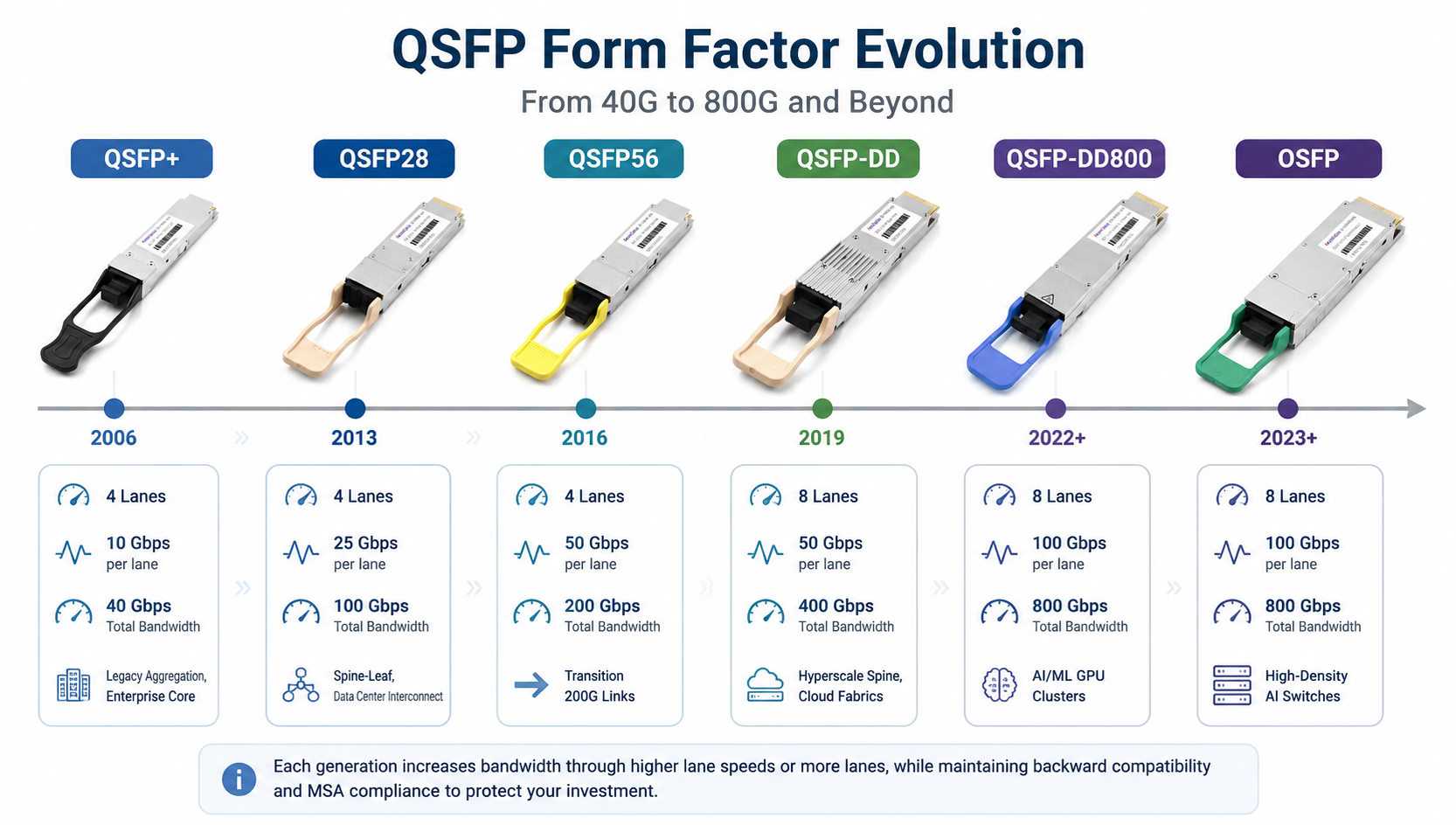
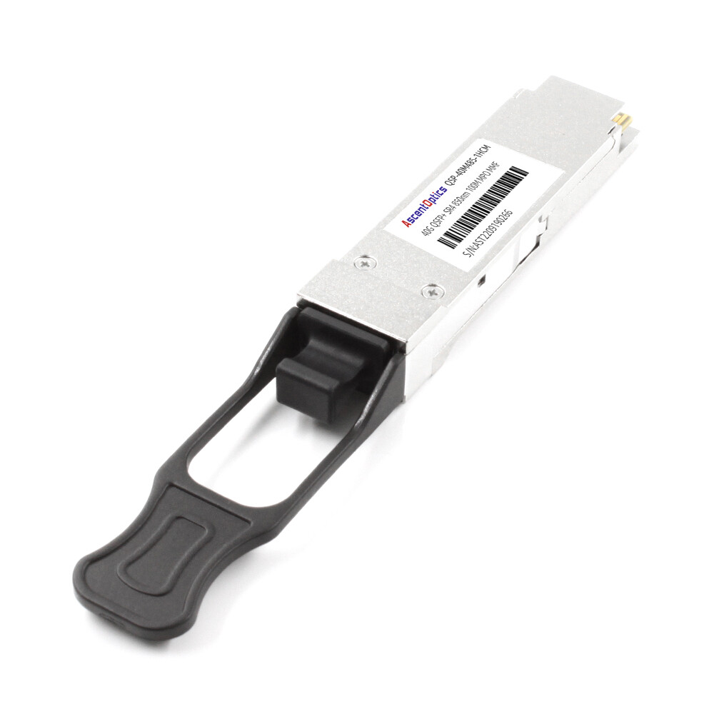
QSFP+ was the first widely deployed generation. It uses four lanes at 10 Gbps each for a total of 40 Gbps. QSFP+ remains common in older aggregation layers and enterprise core switches. QSFP28 ports are designed to accept QSFP+ modules, enabling a smooth migration from 40G to 100G networks.
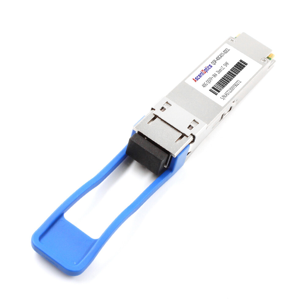
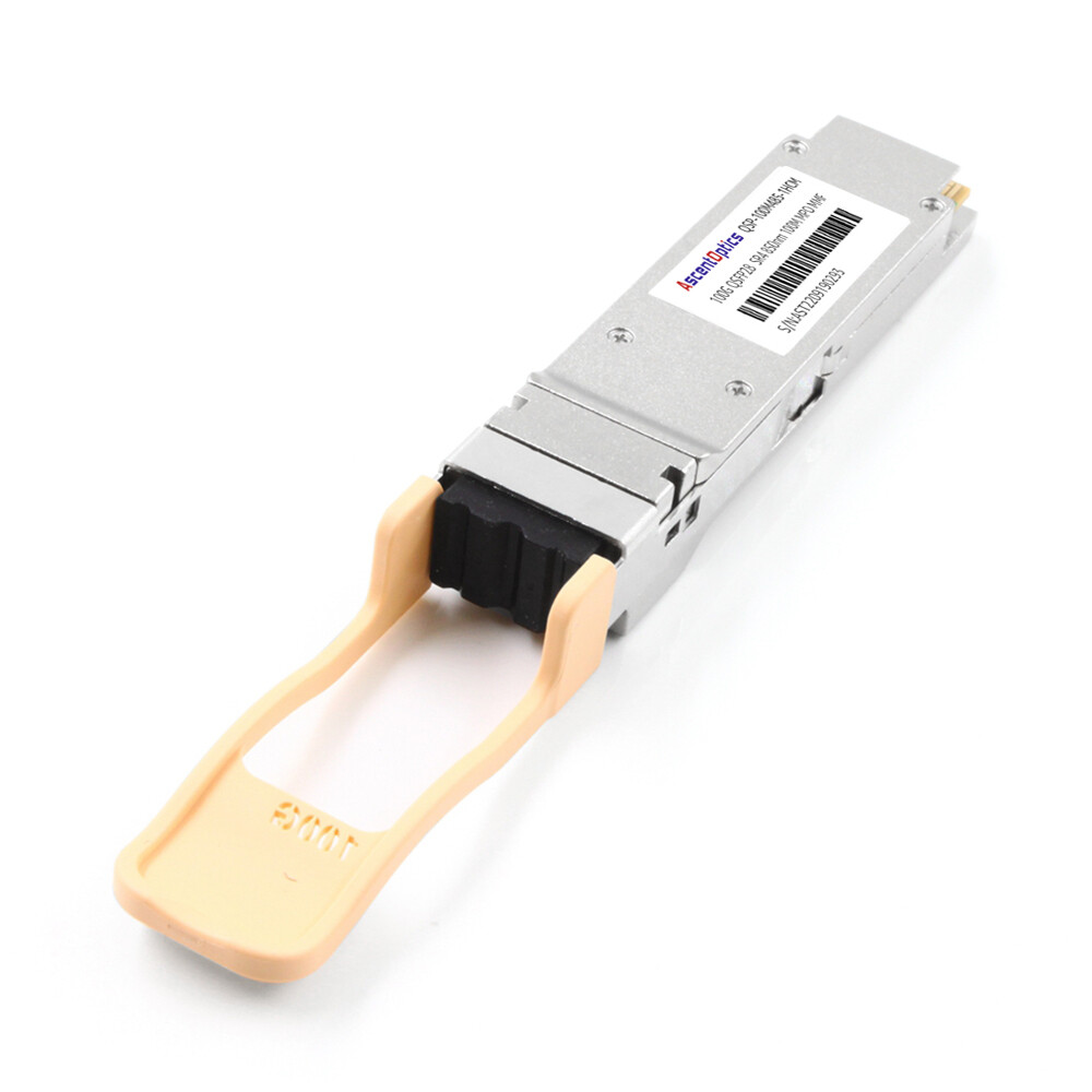
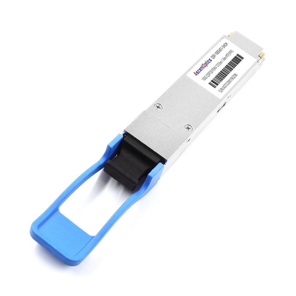
QSFP28 uses four lanes at 25 Gbps each, delivering 100 Gbps total. It is the dominant 100G Ethernet form factor in data centers today. QSFP28 modules support standards such as 100GBASE-SR4, 100GBASE-LR4, 100GBASE-ER4, and CWDM4. They also support breakout modes that split one 100G port into four 25G links.
QSFP56 pushes each of the four lanes to 50 Gbps using PAM4 modulation, achieving 200 Gbps. It serves as a transition form factor between 100G and 400G, though it has seen less adoption than QSFP28 and QSFP-DD.
QSFP-DD, or Quad Small Form-Factor Pluggable Double Density, adds a second row of electrical contacts to double the lane count from four to eight. With eight lanes at 50 Gbps each, QSFP-DD supports 400 Gbps. QSFP-DD supports 400G Ethernet using eight 50G PAM4 electrical lanes, while QSFP-DD800 increases lane speed to 100G PAM4 without changing the mechanical form factor. It is the dominant 400G form factor in hyperscale data centers and is backward compatible with older QSFP modules in the same cage.
QSFP-DD800 and OSFP (Octal Small Form-Factor Pluggable) are the two leading form factors for 800G. QSFP-DD800 keeps the QSFP-DD mechanical envelope while increasing lane speed to 100 Gbps. OSFP uses a slightly larger module with integrated thermal management. The larger form factor provides additional thermal headroom, making OSFP particularly suitable for high-power 800G and future 1.6T optical modules. Both are designed for AI/ML clusters and dense cloud fabrics.
| Form Factor |
Lanes |
Lane Speed |
Total Bandwidth |
Common Use Case |
| QSFP+ |
4 |
10 Gbps |
40 Gbps |
Legacy aggregation, enterprise core |
| QSFP28 |
4 |
25 Gbps |
100 Gbps |
Spine-leaf, data center interconnect |
| QSFP56 |
4 |
50 Gbps |
200 Gbps |
Transition 200G links |
| QSFP-DD |
8 |
50 Gbps |
400 Gbps |
Hyperscale spine, cloud fabrics |
| QSFP-DD800 |
8 |
100 Gbps |
800 Gbps |
AI/ML GPU clusters |
| OSFP |
8 |
100 Gbps |
800 Gbps |
High-density AI switches |
How QSFP Modules Work in Data Center Networks
Understanding how QSFP modules move data helps engineers make better decisions about fiber type, distance, and modulation.
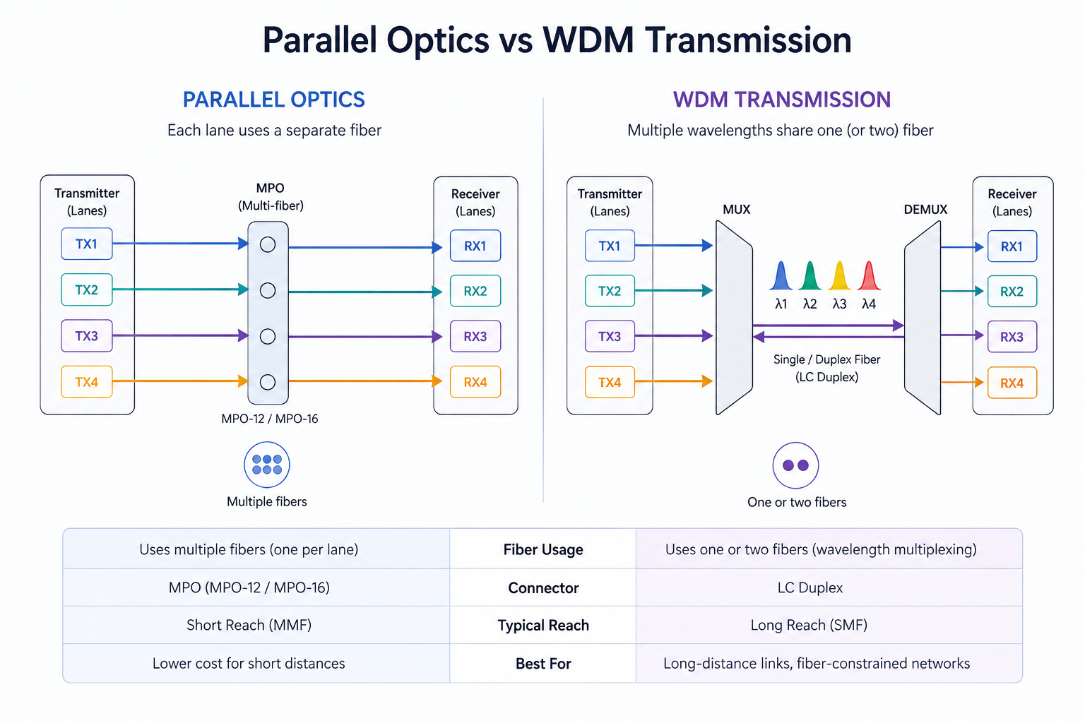
Parallel Optics vs. Wavelength-Division Multiplexing
QSFP modules use two main approaches to reach their aggregate bandwidth. Parallel optics transmit each lane on a separate fiber. A QSFP28 SR4 module, for example, uses four fibers for transmit and four for receive, typically bundled in a single MPO-12 connector. Parallel optics are simple and cost-effective for short reaches.
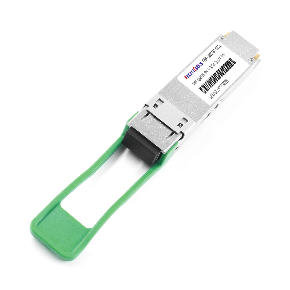
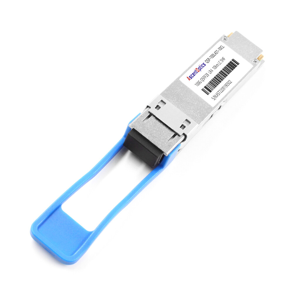
Wavelength-division multiplexing (WDM) combines multiple lanes onto one or two fibers by using different wavelengths. CWDM4 and LR4 modules use WDM to send 100G over duplex LC single-mode fiber. WDM reduces fiber count and is essential for longer distances.
NRZ vs. PAM4 Modulation
Early QSFP generations used non-return-to-zero (NRZ) signaling, where each symbol represents one bit. QSFP28 uses NRZ at 25 Gbps per lane. Higher-speed modules use PAM4 (Pulse Amplitude Modulation 4-level), where each symbol carries two bits. PAM4 doubles the bit rate without doubling the baud rate, but it requires stronger forward error correction and better signal integrity.
Single-lambda 100G QSFP28 modules use PAM4 to send 100 Gbps over a single fiber pair.
Fiber Types: MMF vs. SMF
Multimode fiber (MMF) supports shorter distances, typically up to 100 meters with modern OM4 or OM5 fiber. Although OM5 supports SWDM applications, OM4 remains the dominant multimode fiber in modern Ethernet deployments. MMF uses lower-cost vertical-cavity surface-emitting laser (VCSEL) technology and is common for intra-data center links.
Single-mode fiber (SMF) supports longer distances, from 500 meters to 80 kilometers or more. SMF uses more precise lasers and is required for data center interconnects and telecom applications.
Connectors and Copper Alternatives
QSFP modules use several connector types. MPO connectors are common for parallel optics. LC duplex connectors are standard for WDM and single-lambda modules. For very short links, DAC (Direct Attach Copper) and AOC (Active Optical Cable) assemblies plug directly into QSFP ports without separate fiber jumpers.
QSFP Module Types and Distance Classes
Selecting the right QSFP module starts with distance and fiber type. The following classes cover most data center scenarios.
Short-Reach Modules
QSFP28 SR4 / QSFP-DD SR8 support up to 100 meters over OM4 MMF using parallel optics. These modules handle the majority of intra-data center links, including rack-to-rack and row-to-row connections.
SR-BiDi variants use bidirectional transmission over a single fiber pair, allowing operators to reuse existing duplex MMF infrastructure when upgrading from 10G or 40G.
Medium-Reach Modules
CWDM4 modules transmit 100G over duplex single-mode fiber for up to 2 kilometers. They are cost-optimized for data center interconnects and cloud fabrics.
PSM4 modules use parallel single-mode fiber for distances up to 500 meters or 2 kilometers, depending on the variant. They are often used when MPO cabling is already deployed.
DR4 / FR4 / FR1 modules cover 500 meters to 2 kilometers using PAM4 signaling. Single-lambda variants simplify inventory and reduce fiber complexity.
Long-Reach Modules
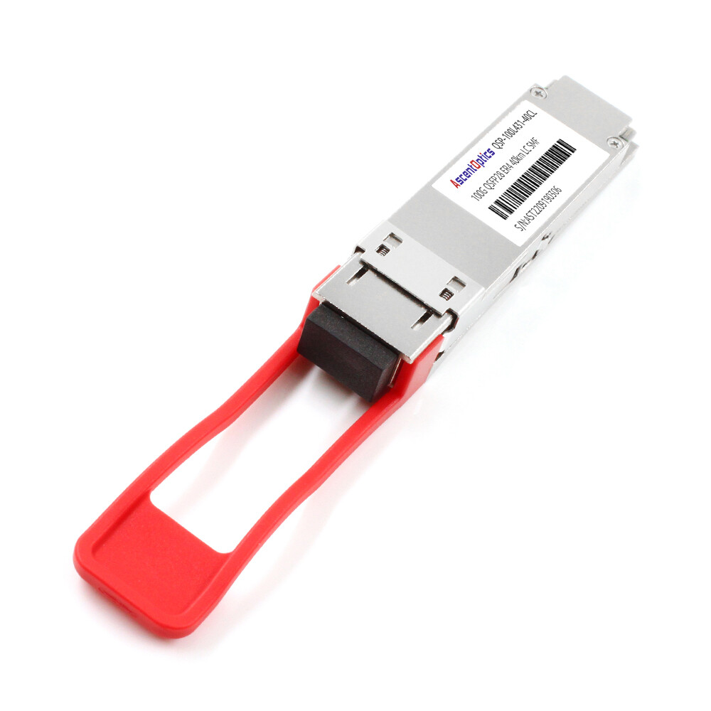
LR4 modules support 10 kilometers over SMF. ER4 extends that to 40 kilometers. 400ZR and OpenZR+ coherent optics extend Ethernet connectivity to 80 km and beyond for metro DCI applications.
Copper and Active Optical Alternatives
For links under 7 meters, DAC cables consume a fraction of the power of optical modules and eliminate transceiver cost. AOC cables extend that to 30 meters or more with slightly higher power but better flexibility.
| Module Type |
Fiber |
Typical Reach |
Connector |
Best Application |
| SR4 / SR8 |
OM4 MMF |
Up to 100m |
MPO-12 |
Intra-data center, rack-to-rack |
| SR-BiDi |
OM4 MMF |
Up to 100m |
Duplex LC |
Fiber-constrained upgrades |
| CWDM4 |
SMF |
2 km |
Duplex LC |
Cost-optimized DCI |
| PSM4 |
SMF |
500m–2km |
MPO-12 |
MPO-cabled facilities |
| LR4 |
SMF |
10 km |
Duplex LC |
Campus/metro DCI |
| ER4 |
SMF |
40 km |
Duplex LC |
Extended reach DCI |
| ZR / ZR4 |
SMF |
80 km+ |
Duplex LC |
Metro / coherent networks |
| DAC |
Copper |
Up to 7m |
QSFP integrated |
Intra-rack, top-of-rack |
| AOC |
Fiber |
Up to 30m |
QSFP integrated |
Intra-row, clean cabling |
Data Center Applications for QSFP Modules
QSFP modules appear at nearly every aggregation layer in modern data centers. The right module depends on the architecture, distance, and traffic pattern.
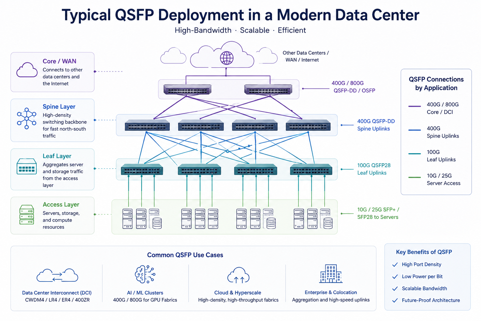
Spine-Leaf Architecture
Spine-leaf networks use QSFP28 or QSFP-DD modules for spine-to-leaf uplinks. Leaf switches connect servers with SFP28 or SFP56, then aggregate traffic into 100G or 400G QSFP uplinks to the spine. Breakout cables let a single QSFP28 spine port fan out to four 25G leaf ports.
Data Center Interconnect (DCI)
For connections between facilities, CWDM4, LR4, and ER4 modules provide cost-effective reaches from 2 kilometers to 40 kilometers. Coherent ZR modules handle longer metro links. DCI modules must balance fiber cost, latency, and optical power budget.
AI/ML GPU Clusters
AI training clusters are the fastest-growing driver of QSFP-DD and 800G modules. GPU fabrics require massive scale-out bandwidth between compute nodes. According to TrendForce, the AI optical transceiver market is expected to reach $26 billion in 2026, up 57% year over year. Much of that demand comes from 800G modules in AI server clusters.
Hyperscale Cloud Networks
Cloud providers deploy QSFP28 and QSFP-DD modules by the million. They prioritize cost, power efficiency, and supply consistency. Many are moving toward single-lambda 100G and 400G designs to simplify logistics and reduce per-bit cost.
Enterprise and Colocation Facilities
Enterprise data centers often standardize on QSFP28 SR4 for intra-facility links, and QSFP28 LR4 or CWDM4 for campus interconnects. Colocation providers value backward compatibility because tenants bring their own switch hardware.
QSFP vs. SFP: When to Use Which in Data Centers
SFP and QSFP modules serve different roles. Choosing between them is rarely a question of which is better. It is a question of which fits the layer.
SFP modules support 1G to 25G per port. They are compact, flexible, and cost-effective for server-facing access ports. QSFP modules consolidate four lanes into one port, delivering 40G to 800G. They excel at aggregation, spine uplinks, and high-density core layers.
The density advantage is significant. A single QSFP28 port can replace four SFP28 ports for the same 100G bandwidth, reducing switch count, cabling, and power. However, SFP remains the right choice for low-density edge connections where 1G, 10G, or 25G is sufficient.
Breakout configurations bridge the two. A QSFP28 port configured in breakout mode supplies four 25G SFP28 links. This is common in spine-leaf designs where the spine runs 100G and the leaf runs 25G server ports.
| Attribute |
SFP / SFP+ / SFP28
|
QSFP / QSFP+ / QSFP28
|
| Per-port bandwidth |
1G–25G
|
40G–800G
|
| Lane count |
1
|
4 or 8
|
| Typical use layer |
Access/edge
|
Aggregation/spine/core
|
| Fiber density |
Lower
|
Higher
|
| Breakout support |
N/A
|
QSFP28 to 4×25G, QSFP-DD to 4×100G
|
| Best for |
Server, edge, low-density
|
Uplinks, DCI, high-density
|
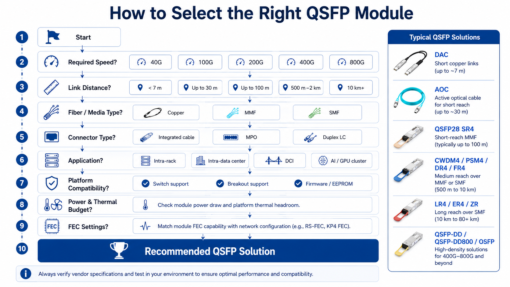
Selecting the Right QSFP Module: A Decision Framework
A structured selection process reduces the risk of compatibility failures and stranded capacity. Follow these six steps.
Step 1: Define Required Data Rate and Reach
Start with the bandwidth the link must carry and the physical distance. Short intra-data center links rarely need more than SR4. Cross-facility links require CWDM4, LR4, or longer-reach modules.
Step 2: Match the Fiber Infrastructure
Confirm the fiber type already installed. MMF facilities should lean toward SR4 or SR-BiDi. SMF facilities can use CWDM4, LR4, or coherent modules. Avoid mixing fiber types unless the migration plan accounts for new cable pulls.
Step 3: Verify Switch and Platform Compatibility
Not all QSFP modules work in all switches. Check the switch vendor’s interoperability matrix for supported transceivers, firmware versions, and breakout modes. Third-party MSA-compliant modules can work, but EEPROM coding and firmware support must match.
Step 4: Plan Power and Thermal Budgets
A typical QSFP28 module consumes 3.5W to 4.5W. A fully loaded 32-port 100G switch can draw 112W to 144W for optics alone. At 400G and 800G, power and thermal density become critical. Verify rack cooling capacity and switch airflow before deployment.
Step 5: Evaluate FEC and Configuration Requirements
100G Ethernet typically uses Reed-Solomon Forward Error Correction (RS-FEC). Some shorter-reach links can use lighter BASE-R FEC. Mismatched FEC settings between endpoints are a common cause of link failures.
Step 6: Consider Future-Proofing and Migration
Choose modules that align with the next upgrade cycle. If the facility moves to 400G within two years, QSFP-DD switches that accept QSFP28 today protect the investment. If the goal is maximum density, plan for QSFP-DD800 or OSFP from the start.
Deployment Best Practices and Common Issues
Even the right module can fail if deployment details are overlooked.
Pre-Deployment Verification
Before installation, validate fiber type, connector cleanliness, link distance, and switch port configuration. Confirm that both ends of the link support the same standard and FEC mode.
Firmware and EEPROM Compatibility
Switch firmware must recognize the module’s EEPROM. Unrecognized modules may link at the wrong speed or not at all. Keep firmware current and verify third-party module support with the switch vendor.
Fiber Cleanliness and Connector Inspection
Dirty fiber end faces are one of the top causes of optical link failures. Inspect and clean MPO and LC connectors before installation. Even a small particle can degrade a 100G or 400G signal.
Thermal Monitoring via DDM/DOM
Digital Diagnostic Monitoring (DDM), also called Digital Optical Monitoring (DOM), reports temperature, transmit power, receive power, and bias current. Use these metrics to spot failing modules before they cause outages.
Troubleshooting Link Failures
When a QSFP link fails, check the following in order:
- 1. Confirm the module is seated fully and the latch is engaged.
- 2. Verify the switch port is configured for the correct speed.
- 3. Check FEC settings on both ends.
- 4. Inspect and clean fiber connectors.
- 5. Review DDM/DOM readings for abnormally high temperature or low receive power.
- 6. Test with a known-good module to isolate hardware failure.
2026 Market Trends: AI, 800G, and the Future of QSFP
The optical transceiver market is growing rapidly. Grand View Research projects the global optical transceiver market will reach 17.4 billion in 2026 and grow to 17.4 billion in 2026 and grow to 36.2 billion by 2033 at an 11.1% CAGR. Within that growth, AI infrastructure is the dominant driver.
AI Clusters Drive 800G Demand
Hyperscale data center traffic is growing over 30% annually, and AI training clusters require massive interconnect bandwidth. FB-LINK and other industry observers note that 800G module shipments are expected to more than double in 2026, with some forecasts exceeding 40 million units.
Form Factor Competition
QSFP-DD and OSFP are competing for dominance at 800G. QSFP-DD offers backward compatibility with older QSFP modules. OSFP offers better thermal headroom and simpler migration to 1.6T. Both will coexist for years.
Silicon Photonics and Power Efficiency
Silicon photonics is moving from niche to mainstream, expected to grow from roughly 25% of datacom transceivers toward two-thirds of shipments. Low-power designs such as Linear Pluggable Optics (LPO) and Co-Packaged Optics (CPO) are gaining attention as data centers struggle with thermal and energy budgets.
1.6T on the Horizon
1.6T optical modules are entering early commercialization. They will likely use OSFP-XD or a similar dense form factor. For most enterprises, 1.6T is still a planning topic. For hyperscalers and AI labs, it is already an architectural consideration.
Supply Chain Considerations
High-speed lasers, DSPs, and optical packaging capacity remain constrained. Procurement teams should plan longer lead times for 800G modules and consider dual-sourcing strategies for critical deployments.
Conclusion
QSFP modules are the backbone of high-speed QSFP data center connectivity. From 40G QSFP+ aggregation to 800G AI cluster fabrics, the QSFP family offers a migration path that protects fiber infrastructure while scaling bandwidth. The key is matching the module to the application: SR4 for intra-data center links, CWDM4 or LR4 for interconnects, and QSFP-DD or OSFP for next-generation AI fabrics.
Successful deployments depend on more than choosing the right speed. Engineers must verify compatibility, plan thermal budgets, inspect fiber, and align module selection with the broader network roadmap.
As AI clusters continue to scale beyond 100,000 GPUs and Ethernet evolves toward 1.6T, QSFP technologies will remain a critical building block for high-density, energy-efficient optical interconnects. Understanding the strengths of each QSFP generation helps data center operators build networks that meet both today’s bandwidth requirements and tomorrow’s scalability demands.
Post Views: 701