As Ethernet speeds continue to scale from 100G to 400G and 800G, even minor issues such as connector contamination, FEC mismatches, or excessive insertion loss can cause significant packet errors or complete link failures. A structured troubleshooting process helps engineers quickly isolate faults while minimizing downtime.
Troubleshooting QSFP optical modules is crucial for ensuring the stable operation of high-speed data center networks. Common issues affecting 40G, 100G, and 400G links include abnormal optical power, elevated bit error rates, compatibility problems, and fiber end-face contamination. Link issues can be rapidly identified and resolved through Digital Diagnostic Monitoring (DDM) analysis, physical layer testing, and the review of device logs.
What Is QSFP Troubleshooting?
QSFP troubleshooting is the systematic diagnosis of physical, electrical, firmware, and optical issues that affect Quad Small Form-Factor Pluggable transceivers. It applies to the full QSFP family, including QSFP+ (40G), QSFP28 (100G), and QSFP-DD (400G/800G) modules.
Engineers verify connector cleanliness, module seating, and cable integrity before they look at EEPROM data, CMIS state machines, FEC configuration, or BER statistics. This bottom-up approach matters because the root cause is usually optical, not logical. This bottom-up approach is effective because most QSFP link failures originate in the physical layer—including fiber contamination, connector damage, incorrect polarity, or optical power degradation—rather than software configuration.
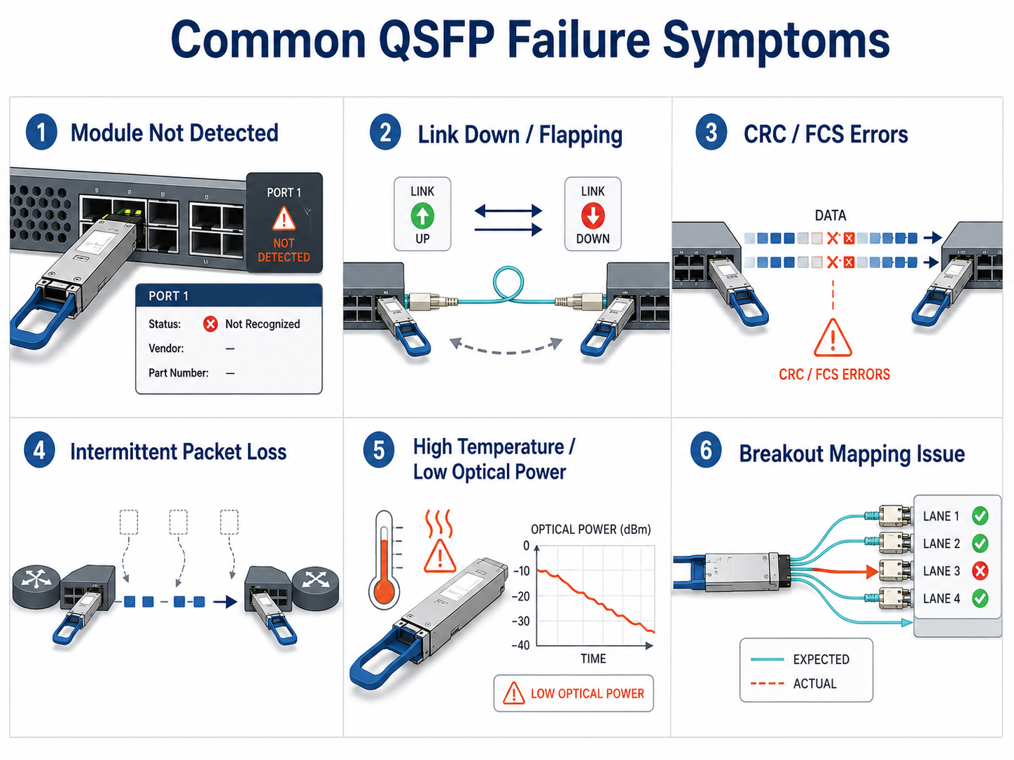
Common QSFP Failure Symptoms
Most field reports fall into six categories. Recognizing the symptom narrows the diagnostic path immediately.
- 1. Module not detected or unsupported transceiver error. The switch refuses to recognize the module, often due to vendor lock-in, CMIS version mismatch, or power-class issues.
- 2. Link down or link flapping. The interface cycles between up and down states, usually caused by dirty connectors, FEC mismatches, or marginal optical power.
- 3. CRC/FCS errors and high bit error rate (BER). Packets arrive corrupted because of signal degradation, crosstalk, or PAM4 lane imbalance on high-speed links.
- 4. Intermittent packet loss. Traffic drops in bursts, often tied to thermal throttling or unstable RX power.
- 5. Degraded optical power or high temperature. DDM readings drift outside normal ranges, warning of end-of-life or airflow problems.
- 6. Breakout port mapping issues. A 100G QSFP28 to 4x25G breakout shows partial connectivity because of lane polarity or speed mismatch.
- 7. LOS (Loss of Signal). LOS (Loss of Signal) alarms caused by insufficient received optical power or disconnected fiber.
Phase 1: Physical Layer Verification
Physical-layer problems cause the majority of QSFP failures. According to EXFO research, connector contamination affects up to 96% of installers and 80% of network operators in fiber-optic environments (EXFO white paper). For 400G links specifically, industry field data suggests that 65–70% of failures stem from connector contamination.
Visual Inspection Checklist
Start with the obvious before opening a CLI.
- •Confirm the module is fully seated until the latch clicks.
- •Inspect the bail clasp and cage for bent pins or damage.
- •Look for dust caps still installed on optical ports.
- •Check cable jacket condition for kinks, cracks, or tight bends.
- •Verify ambient temperature and airflow around the switch faceplate.
Connector Cleaning for MPO/MTP and LC
Cleaning procedures differ by connector type.
LC connectors:
- 1. Inspect the ferrule tip with a 400x fiber microscope.
- 2. Use a one-click cleaner or a lint-free wipe with fiber-grade solvent.
- 3. Move from wet to dry in a single direction.
- 4. Re-inspect before mating.
MPO/MTP connectors:
- 1. Remove the connector from the adapter.
- 2. Use an MPO cleaner that matches the ferrule width.
- 3. Clean both male and female sides.
- 4. Verify guide pins are straight and not recessed.
Safety note: Never look directly into a fiber end face or transceiver port while the laser is active. QSFP modules use Class 1M or higher lasers that can cause eye injury. Always inspect before cleaning and inspect again after cleaning (“Inspect → Clean → Inspect”), following IEC 61300-3-35 best practices.
Module Seating and Latch Verification
A partially seated module can cause intermittent high-speed lane failures. Remove the module, inspect the electrical contacts for oxidation or debris, and reinstall it with firm pressure until both latches engage. On belly-to-belly cage designs, upper-row modules often run 10–15°C hotter than lower-row modules due to thermal shadowing. If the upper port fails repeatedly, test the same module in a lower slot.
Cable, Polarity, and Bending Radius Checks
- •Bending radius: Single-mode fiber should not bend tighter than 30 mm; multimode fiber no tighter than 20 mm.
- •Polarity: For 400G SR8 and breakout cables, Method B is widely deployed for parallel-optics Ethernet applications, although the required polarity depends on the cabling architecture.
- •Cable type: Verify that the patch cord matches the module. A single-mode module mated to multimode fiber will not establish a stable link.
Environmental and Thermal Checks
Commercial QSFP modules typically operate from 0°C to 70°C case temperature. Use DDM readings to confirm the module is not overheating. If the intake air exceeds 45°C, cooling—not the module—is the problem.
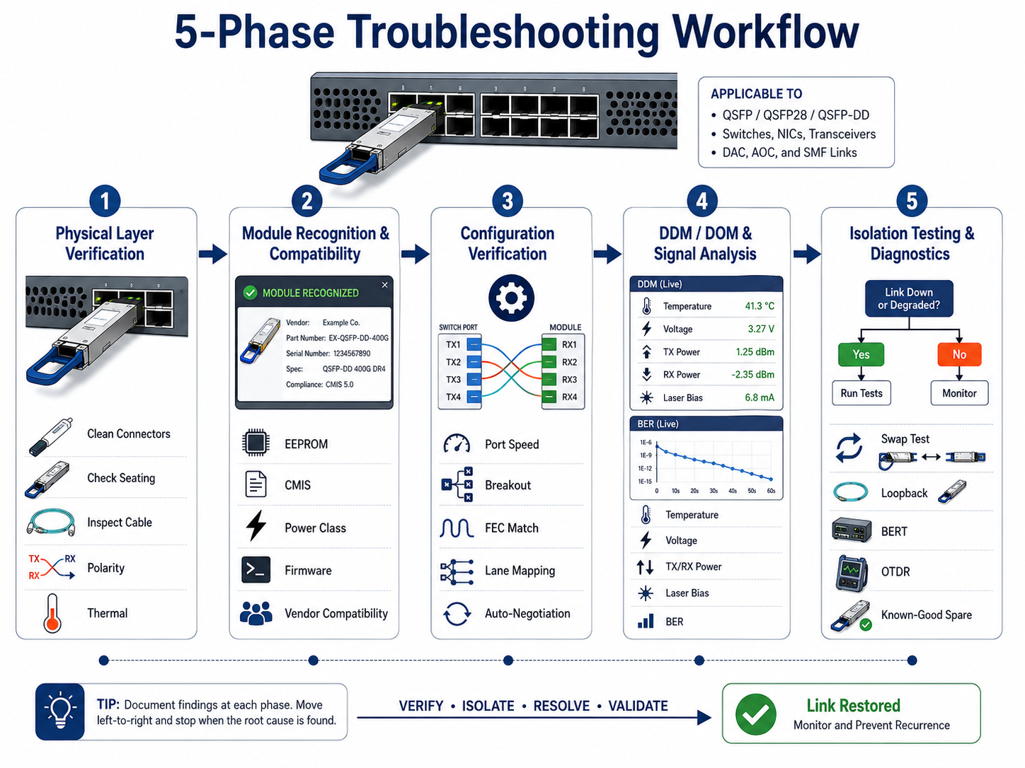
Phase 2: Module Recognition and Compatibility
If the physical layer checks out but the module is still not detected, the issue is usually firmware, EEPROM coding, or power class.
Power Class and Thermal Budget
QSFP-DD modules can draw up to 8W, with coherent ZR/ZR+ modules drawing 15–25W. If a switch port cannot deliver the required power class, the module may not initialize or may reset randomly. Check the platform hardware guide for maximum power per port and total thermal budget.
Firmware and CMIS Version Mismatch
Older switch firmware may not decode CMIS 4.0 or 5.0 data correctly. If the module reports as generic or unknown, update the switch to the minimum software version listed in the hardware compatibility matrix. This is especially common when deploying new QSFP-DD modules in switches that were first released for QSFP28.
Multi-Vendor Command Reference Table
| Platform |
Show Module |
Show Optics |
Show FEC |
| Cisco IOS-XR |
show inventory |
show controllers optics |
show fec event-log |
| Cisco NX-OS |
show module |
show interface transceiver |
show interface fec |
| Arista EOS |
show version |
show interfaces transceiver |
show interfaces phy detail |
| Juniper JunOS |
show chassis hardware |
show interfaces diagnostics optics |
show interfaces extensive |
| SONiC/Linux |
show platform summary |
show interface transceiver eeprom |
ethtool –show-fec |
Phase 3: Configuration Verification
Once the module is recognized, the next set of failures is usually configuration.
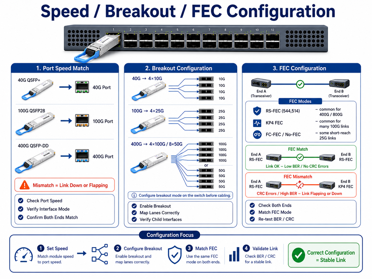
Port Speed and Breakout Configuration
A QSFP28 port may default to 40G if the breakout is not configured. Verify that the port speed matches the module rating. For breakout applications:
- •40G QSFP+ → 4x10G
- •100G QSFP28 → 4x25G
- •400G QSFP-DD → 4x100G or 8x50G
Each breakout lane must map to the correct physical port on the switch ASIC.
FEC Mode Consistency
Forward Error Correction (FEC) is mandatory for 400G links and recommended for many 25G/100G deployments. Both ends of a link must use the same FEC mode. Common modes include:
- •RS-FEC (544,514) is mandatory for most PAM4-based 200G, 400G, and 800G Ethernet interfaces.
- •KP4 FEC is commonly used for 50G PAM4 electrical lanes.
- •FC-FEC or NO-FEC for short-reach 25G links
A mismatch typically results in link flapping or extremely high CRC counts.
Lane Mapping and Polarity
In breakout cables, lane mapping determines which electrical lane drives which optical fiber. If lane 0 on the switch maps to fiber 4 instead of fiber 1, the link will not establish correctly. Use the cable datasheet and switch documentation to verify the mapping.
Auto-Negotiation Settings
For DAC and AOC cables, auto-negotiation may fail if the two endpoints advertise different capabilities. Try forcing the speed and FEC mode on both ends before replacing the cable.
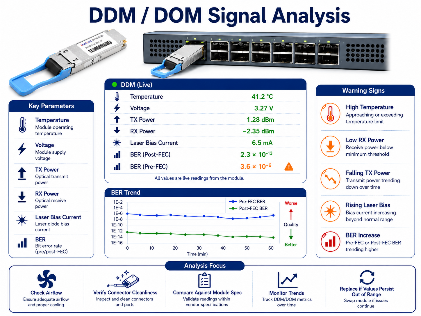
Phase 4: DDM/DOM and Signal Quality Analysis
Digital Diagnostic Monitoring (DDM), also called Digital Optical Monitoring (DOM), gives you a live view of module health. The most useful parameters are temperature, voltage, TX optical power, RX optical power, and laser bias current.
Critical DDM Parameters and Thresholds
| Parameter |
Normal Range |
Warning Sign |
Likely Cause |
| Temperature |
0–70°C (commercial) |
>70°C sustained |
Poor airflow, blocked vents, high ambient temperature |
| Voltage |
3.135–3.465V |
Outside range |
Power supply issue, poor seating |
| TX Power |
Per module spec (e.g., -2 to +3 dBm) |
>3 dB below spec |
Laser degradation, end-of-life |
| RX Power |
Above sensitivity with margin |
Below sensitivity or above overload |
Dirty connector, fiber bend, distance mismatch |
| Laser Bias Current |
Stable baseline |
>20% increase over baseline |
VCSEL or laser aging, imminent failure |
Pro tip: Laser bias current trend is often the earliest indicator of module wear. Track it weekly and plan a replacement before the link degrades.
TX/RX Power Ranges by Module Type
Values below are typical operating ranges. Always refer to the module datasheet and applicable IEEE specifications for exact transmitter output power and receiver sensitivity.
| Module Type |
Typical TX Power |
Typical RX Sensitivity |
Fiber Type |
| 40GBASE-SR4 |
-7.6 to -1 dBm |
-9.5 dBm max |
MMF |
| 100GBASE-SR4 |
-8.4 to +2.4 dBm |
-10.3 dBm max |
MMF |
| 100GBASE-LR4 |
-4.3 to +4.5 dBm |
-10.6 dBm max |
SMF |
| 400GBASE-SR8 |
-6 to +4 dBm |
-8.4 dBm max |
MMF |
| 400GBASE-DR4 |
-2.9 to +4 dBm |
-6.6 dBm max |
SMF |
| 800GBASE-SR8 |
-4.6 to +4.0 dBm (per lane) |
≤ -6.9 dBm (per lane) |
MMF |
| 800GBASE-DR8 |
-2.4 to +4.0 dBm (per lane) |
≤ -5.9 dBm (per lane) |
SMF |
Always compare live readings against the module datasheet, not generic values.
Temperature and Voltage Monitoring
High temperature accelerates laser aging and increases BER. If the module runs near 70°C, check the switch intake temperature and cable management. Empty slots should have blanking panels installed to preserve front-to-back airflow.
Voltage readings outside 3.135–3.465V usually indicate a seating or power-distribution problem. Remove and reseat the module before replacing it.
Pre-FEC and Post-FEC BER Analysis
Bit error rate is the final judge of link quality.
- •Pre-FEC BER for 400G links should be below 4 × 10⁻⁴.
- •Post-FEC BER should be below 1 × 10⁻¹²; any post-FEC errors indicate uncorrectable problems.
If pre-FEC BER is high but post-FEC BER is clean, the link is marginal but functional. If post-FEC BER shows errors, the link will drop soon.
When to Replace vs. Re-seat
Replace the module when:
- •TX power has dropped more than 3 dB from spec.
- •Laser bias current has risen more than 20% above baseline.
- •Pre-FEC BER remains high after cleaning and reseating.
- •Temperature and voltage are normal, but errors persist.
Re-seat or clean when:
- •The link works after reseating.
- •RX power is low but improves after connector cleaning.
- •The module works on another port or switch.
Phase 5: Isolation Testing and Advanced Diagnostics
When the cause is not obvious, isolate variables one at a time.
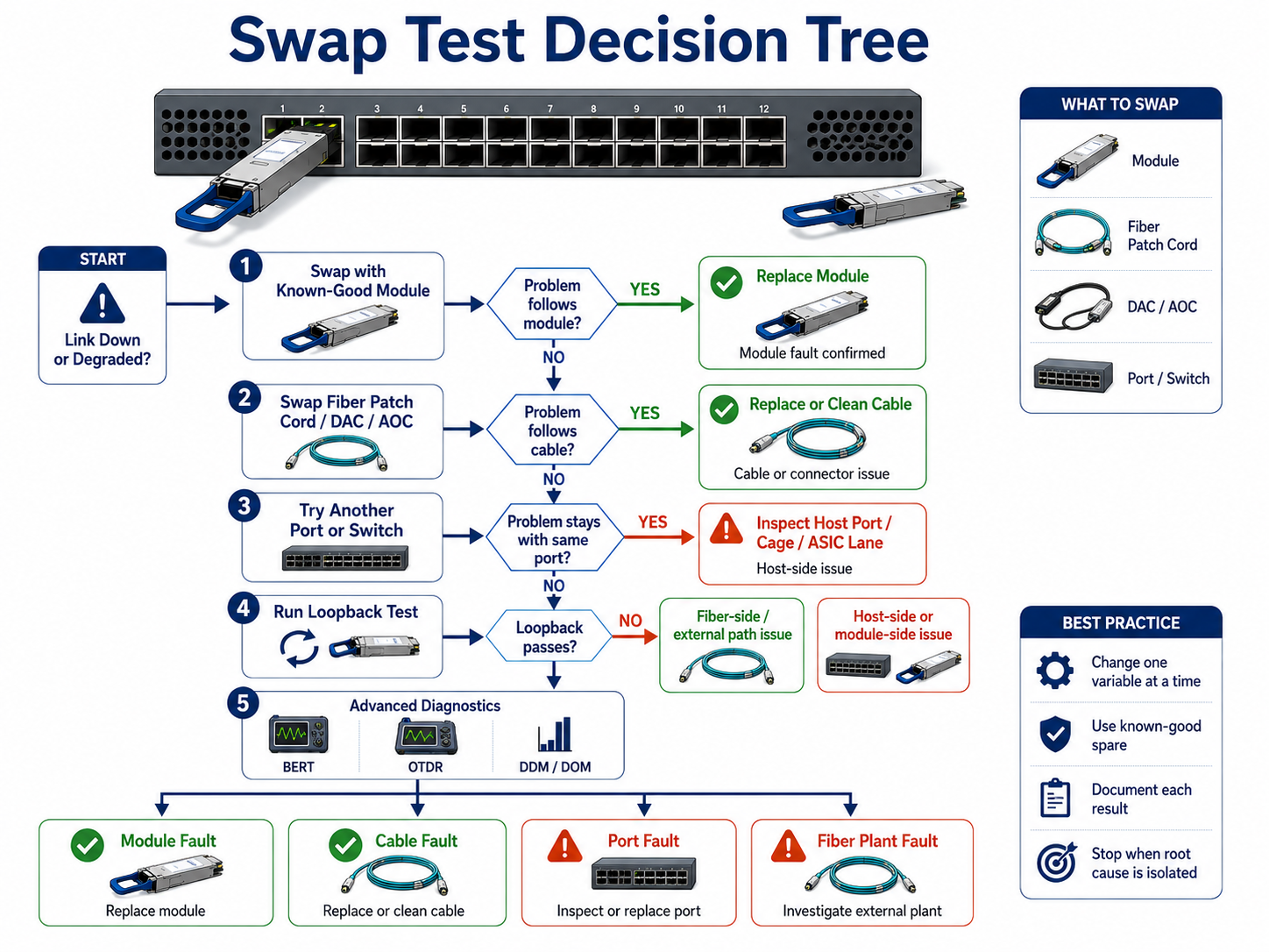
Swap Test Decision Tree
- 1. Swap the module with a known-good spare in the same port.
- 2. If the problem follows the module, replace it.
- 3. If the problem stays with the port, inspect the cage and host ASIC lane.
- 4. Swap the fiber patch cord with a known-good cable.
- 5. If the problem follows the cable, replace or clean the cable plant.
Loopback and BERT Testing
Loopback modules send the transmitter output directly back to the receiver. They help determine whether the issue is host-side or fiber-side. If a loopback test passes, the switch port and module electronics are healthy.
For high-speed links, a Bit Error Rate Tester (BERT) validates signal integrity across all lanes. This is the gold standard for 400G/800G troubleshooting.
Cable Substitution and OTDR
If optical power is marginal, substitute the patch cord first. If that does not resolve the issue, use an Optical Time-Domain Reflectometer (OTDR) to locate breaks, bends, or high-loss splices in the cable plant.
Identifying Host-Side vs. Fiber-Side Issues
| Symptom |
Likely Source |
| Module not detected |
Host side (firmware, EEPROM, power) |
| CRC errors on one lane only |
Host ASIC or module lane |
| CRC errors on all lanes |
Fiber side or module transmitter |
| Link flaps after cable move |
Fiber side (connector, polarity, bend) |
| High temperature warnings |
Environment or host airflow |
Preventive Maintenance and Best Practices
The best troubleshooting is the failure that never happens.
Scheduled Cleaning Cadence
Clean every optical connector before installation, even factory-sealed cables. After installation, inspect and clean connectors every three to six months in high-density environments.
DDM Trending and Alerting
Collect DDM readings into a monitoring system. Set alerts for:
- •Temperature above 65°C
- •RX power below sensitivity plus 3 dB of margin
- •Laser bias current is more than 10% above baseline
- •Pre-FEC BER above 1 × 10⁻⁴
Trending catches degradation weeks before a hard failure.
Sparing Strategy and RMA Guidance
Keep spare modules on site based on deployment size:
- •Top-of-rack deployments: 1–2% sparing ratio
- •Core/spine networks: 2–5% sparing ratio
- •AI clusters with high thermal stress: 5% or higher
Insertion Loss Budget
Verify total channel insertion loss remains within IEEE specifications after every MAC move or patch panel modification.
QSFP Troubleshooting FAQ
Q1. Why is my QSFP module not detected?
A QSFP module may not be detected because of vendor lock-in, CMIS version incompatibility, insufficient power class, poor seating, or outdated switch firmware. Start by reseating the module, checking switch logs for unsupported-transceiver errors, and verifying the minimum firmware version.
Q2. Why does my QSFP link keep flapping?
Link flapping is usually caused by connector contamination, FEC mismatch, MPO polarity errors, or thermal throttling. Clean and inspect connectors first, then verify FEC configuration and optical power levels.
Q3. What DDM values indicate a failing QSFP?
Rising laser bias current, declining TX power, high temperature, and low RX power are the main warning signs. A laser bias current increase above 20% of baseline is a strong indicator that the module is approaching end-of-life.
Q4. How do I clean an MPO connector?
Inspect the connector with a 400x fiber microscope, clean it with an MPO-specific cleaner, verify guide pins are straight, and re-inspect before mating. Always clean both male and female sides.
Q5. Why does a QSFP work in one switch but not another?
Different switches enforce different vendor-lock policies, power-class limits, firmware capabilities, and FEC modes. A module may be rejected by one platform while accepted by another, even if both support the same form factor.
Conclusion
Successful QSFP troubleshooting begins with the physical layer. By following a structured five-phase approach—from connector inspection and compatibility verification to DDM analysis and isolation testing—network engineers can quickly identify root causes, reduce downtime, and improve long-term network reliability. As 400G and 800G deployments continue to expand in AI and cloud data centers, proactive monitoring and preventive maintenance become increasingly important for maintaining high-speed optical connectivity.
Post Views: 614