A single QSFP module can move 100 gigabits per second through a port barely larger than a thumbnail. In hyperscale data centers, that same form factor now scales to 400G and 800G, feeding the east-west traffic demands of AI training clusters and cloud fabrics. Yet the QSFP family is not one product; it is a continuum of standards, lane speeds, modulation schemes, and optical reaches that can trip up even experienced network engineers.
What Is a QSFP Module?
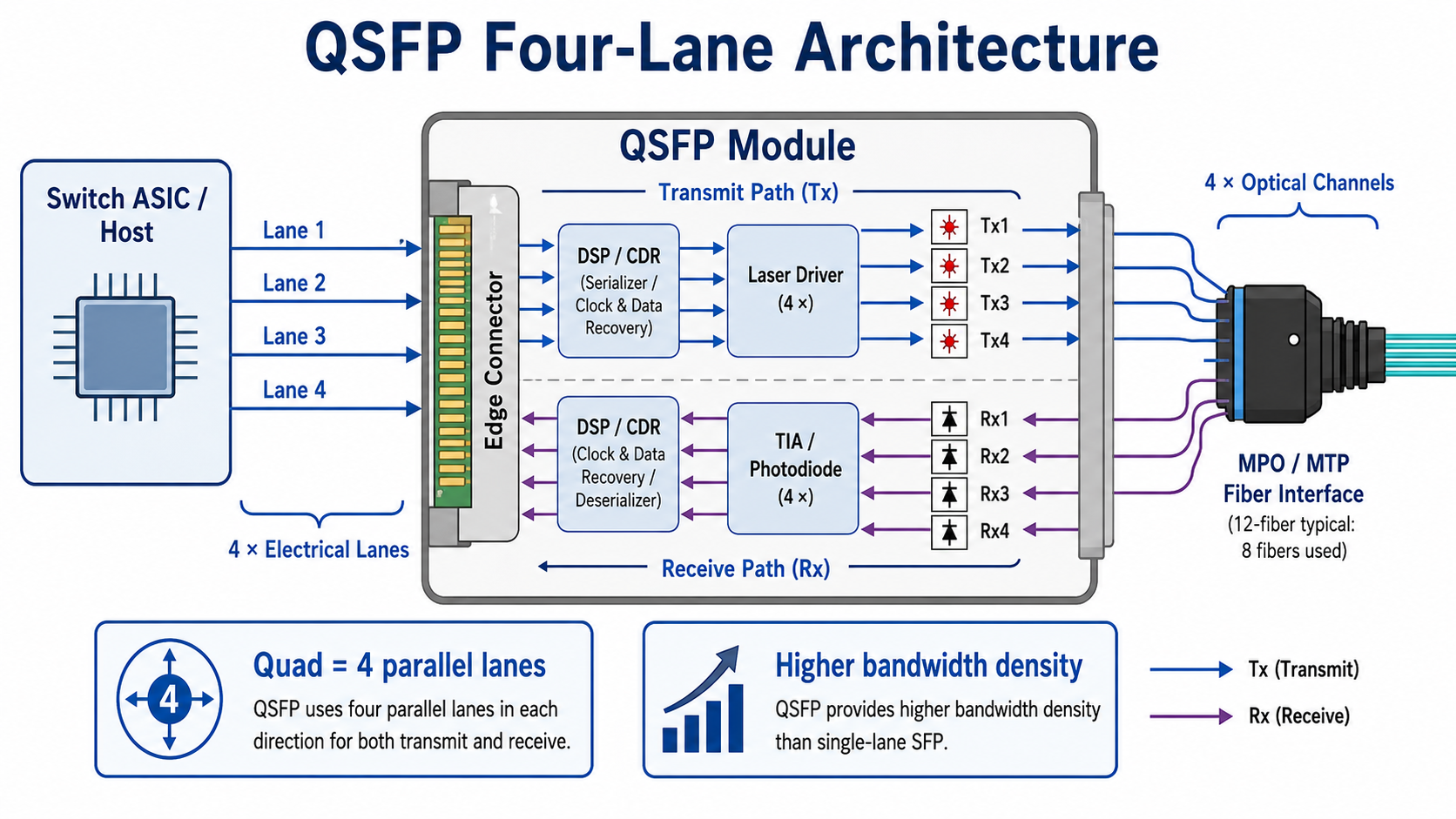
A QSFP module is a compact, hot-pluggable optical transceiver that connects switches, routers, servers, and storage systems over fiber optic cable. The name stands for Quad Small Form-factor Pluggable. The “Quad” refers to the four independent transmit and receive lanes packed inside one module. Unlike SFP, which carries a single lane, a QSFP module transmits and receives four lanes in parallel, multiplying bandwidth density without multiplying port count.
QSFP modules conform to Multi-Source Agreement (MSA) mechanical and electrical specifications. That MSA foundation is why modules from different suppliers often fit and function in the same switch cage, as long as the host platform recognizes the module profile. Modern QSFP modules also include Digital Diagnostic Monitoring (DDM) or Digital Optical Monitoring (DOM), giving operators real-time readings of temperature, voltage, transmit power, receive power, and laser bias current.
The form factor has become the workhorse of high-density networking because it balances bandwidth, port density, and hot-swap serviceability. Network engineers can replace or upgrade a qsfp transceiver without powering down the switch, a critical feature in 24/7 data center environments.
What Does QSFP Stand For?
- •Quad — four transmit, and four receive lanes operate simultaneously.
- •Small — the module occupies roughly the same faceplate area as legacy SFP ports, just deeper.
- •Form-factor — the physical dimensions, electrical pinout, and thermal envelope are standardized.
- •Pluggable — modules insert into a cage and can be swapped without tools or downtime.
That combination is what lets a 1U switch deliver dozens of 100G or 400G ports in a single chassis.
How QSFP Modules Work
Inside a QSFP optical module, electrical signals from the switch ASIC reach the module through a high-speed edge connector. A laser driver converts those electrical lanes into optical signals. On the receive side, photodiodes detect incoming light, and a transimpedance amplifier converts it back into electrical data.
A Digital Signal Processor (DSP) often performs signal equalization, retiming, clock recovery, and PAM4 processing. Forward Error Correction (FEC) is typically implemented by the host ASIC or NIC, although some advanced optical modules may participate in FEC-related functions.
Early QSFP generations used Non-Return-to-Zero (NRZ) signaling, sending one bit per symbol. As lane rates climbed past 25 Gbps, signal integrity limitations pushed newer generations to PAM4 (Pulse Amplitude Modulation 4-level), which encodes two bits per symbol. PAM4 doubles throughput at the same baud rate but requires stronger FEC and tighter signal-to-noise margins. Understanding that shift explains why QSFP56, QSFP112, and QSFP-DD modules place higher demands on host platforms than older QSFP+ modules.
QSFP Modules in AI and HPC Networks
Modern AI clusters built on NVIDIA, AMD, and custom accelerator platforms rely heavily on 400G and 800G QSFP-DD or OSFP optics. High-bandwidth, low-latency interconnects are essential for GPU-to-GPU communication during distributed training. As model sizes continue growing, demand for 800G and future 1.6T optical connectivity is accelerating.
The QSFP Family Tree: QSFP+, QSFP28, QSFP56, QSFP112, and QSFP-DD
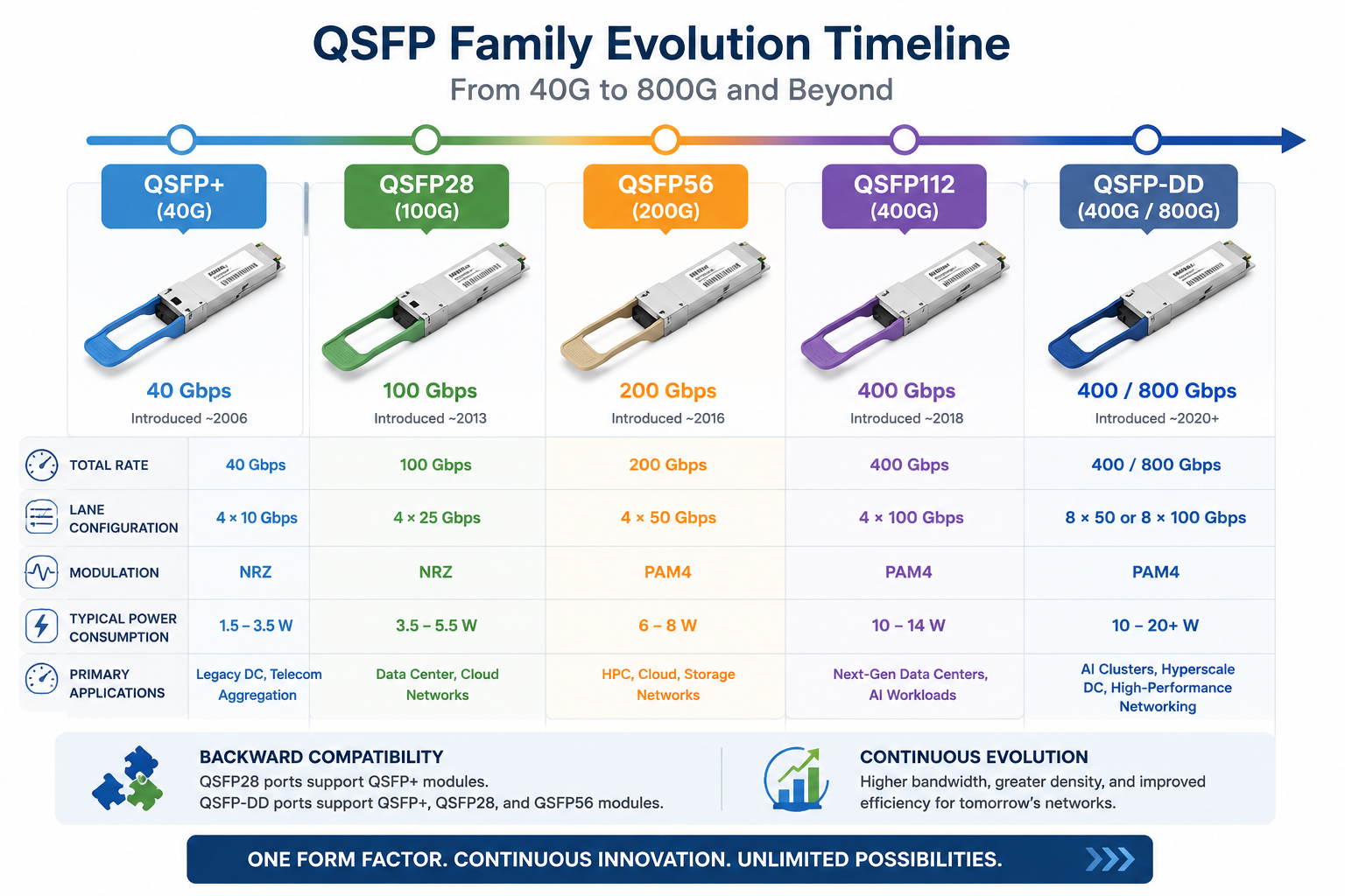
The QSFP form factor has evolved through several generations. Each generation preserves the same mechanical footprint or a backward-compatible cage, but the electrical interface and lane speed change.
| Generation |
Total Rate |
Lane Config |
Modulation |
Typical Power |
Common Variants |
| QSFP+ (40G) |
40 Gbps |
4 × 10 Gbps |
NRZ |
1.5–3.5 W |
SR4, LR4, ER4, PSM4, BiDi |
| QSFP28 (100G) |
100 Gbps |
4 × 25 Gbps |
NRZ |
3.5–5.5 W |
SR4, LR4, ER4, CWDM4, PSM4 |
| QSFP56 (200G) |
200 Gbps |
4 × 50 Gbps |
PAM4 |
6–8 W |
SR4, LR4, ER4, FR4 |
| QSFP112 (400G) |
400 Gbps |
4 × 100 Gbps |
PAM4 |
10–14 W |
SR4, DR4, FR4, LR4 |
| QSFP-DD (400G/800G) |
400–800 Gbps |
8 × 50–100 Gbps |
PAM4 |
10–20 W+ |
SR8, DR4/DR8, FR4, LR4, ZR/ZR+ |
That table is the foundation for most QSFP decisions. Engineers typically start with the required data rate, then narrow by reach, fiber type, and host compatibility.
QSFP+ (40G)
QSFP+ was the first mass-market quad-lane form factor. It delivers 40 Gbps using four 10 Gbps lanes and remains common in legacy aggregation switches, older data center fabrics, and telecom backhaul where 40G capacity is sufficient.
Common optical variants include:
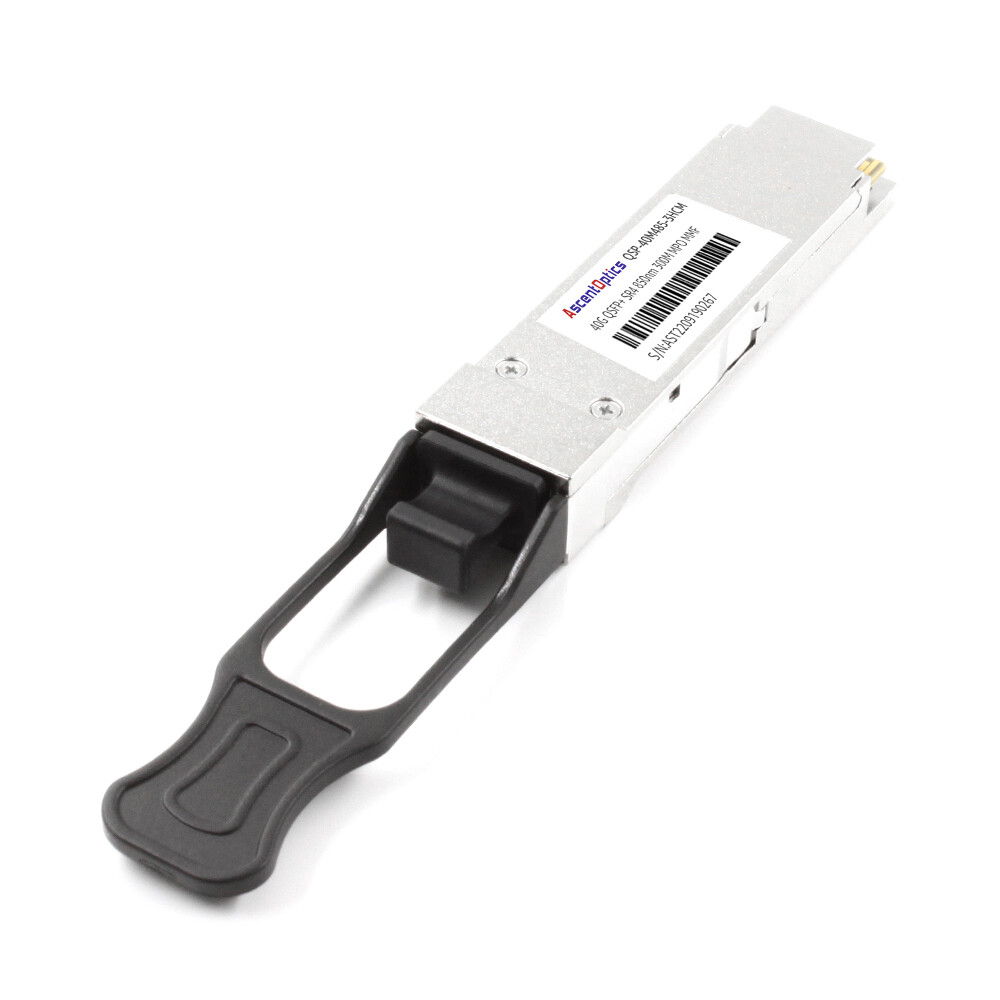
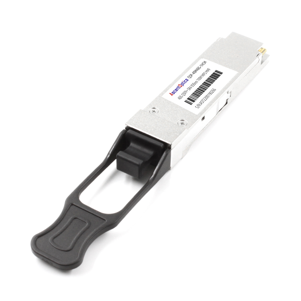
- •40GBASE-SR4: multimode fiber, up to 100 m, MPO/MTP connector
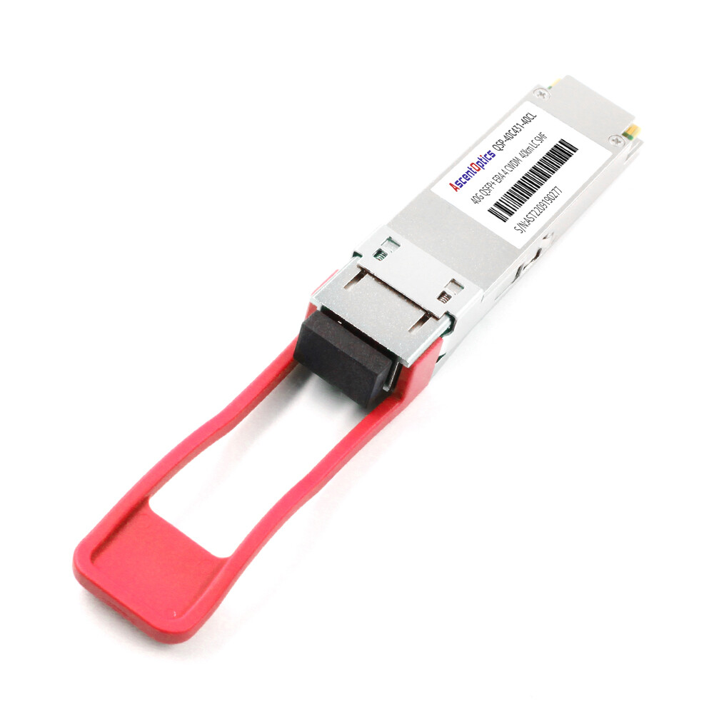
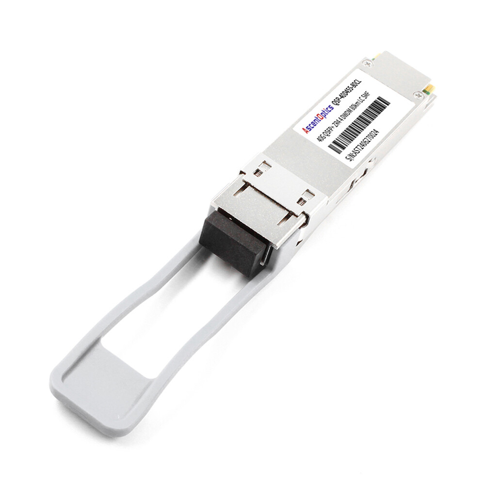
- •40GBASE-LR4: single-mode fiber, 10 km, LC duplex connector
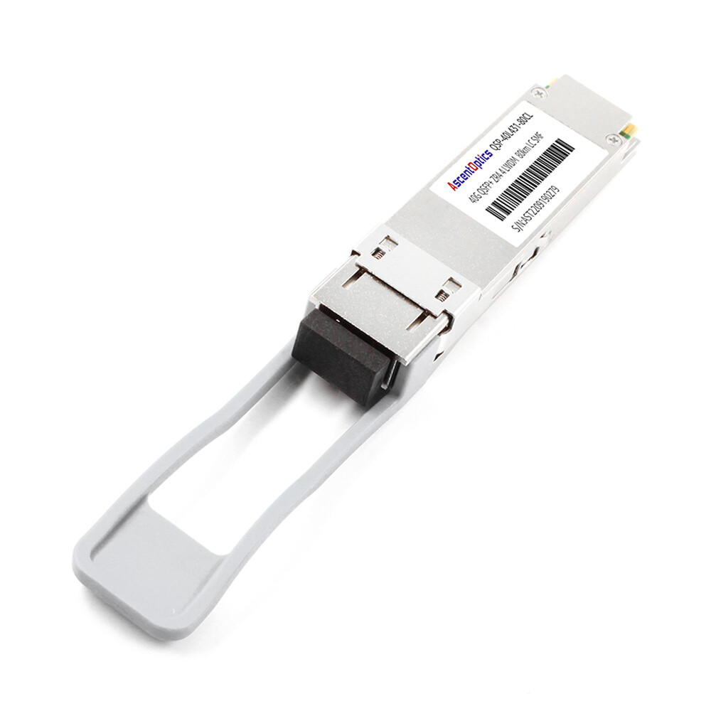
- •40GBASE-ER4: single-mode fiber, 40 km
- •40GBASE-PSM4: single-mode parallel, up to 10 km
- •40GBASE-BiDi: bidirectional over multimode, cost-effective upgrade path
If you are maintaining a legacy fabric, what QSFP stands for covers the 40G origins in more detail.
QSFP28 (100G)
QSFP28 is the dominant 100G form factor in modern data centers. It uses four 25 Gbps lanes and supports the same cage dimensions as QSFP+, which created useful migration flexibility.
A key compatibility rule: QSFP28 ports can accept QSFP+ modules and negotiate down to 40 Gbps, but QSFP+ ports generally cannot accept QSFP28 modules. The mechanical cage is identical, but the electrical interface differs (XLPPI for QSFP+ versus CAUI-4 for QSFP28). That distinction trips up many upgrades.
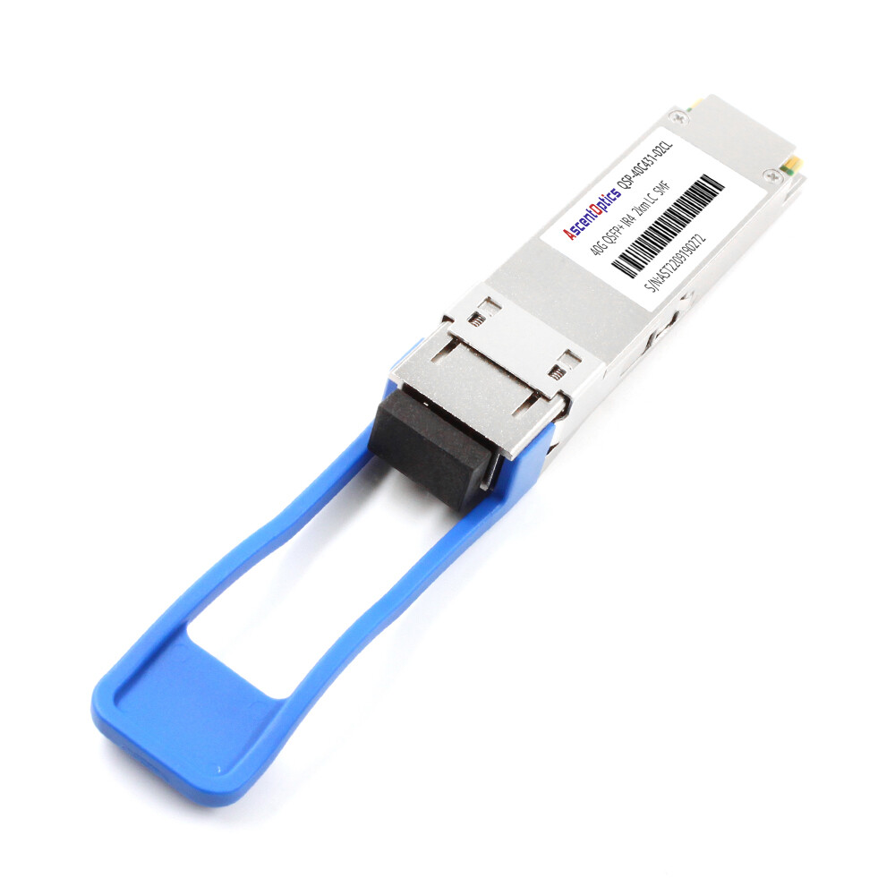
Common variants include 100GBASE-SR4 for short-reach data center links, 100GBASE-LR4 for 10 km single-mode connections, 100GBASE-ER4 for extended reach, and 100GBASE-CWDM4 or 100GBASE-PSM4 for cost-optimized 2 km and 10 km links. You can compare the two generations directly in our QSFP vs QSFP28 guide.
QSFP56 (200G)
QSFP56 doubles the lane rate to 50 Gbps using PAM4 modulation. It is a stepping stone between 100G and 400G, popular in high-performance computing (HPC), cloud clusters, and storage networks, where 200G per port is the sweet spot.
Because it uses PAM4, QSFP56 requires host platforms with 50G-PAM4 SerDes and FEC support. Not every 100G switch can be firmware-upgraded to accept QSFP56 modules.
QSFP112 (400G)
QSFP112 squeezes 400 Gbps through four 100 Gbps PAM4 lanes. It keeps the same QSFP mechanical envelope as QSFP+ and QSFP28, making it attractive for switches that need 400G density without moving to the larger QSFP-DD or OSFP cages.
The trade-off is thermal headroom and power dissipation. QSFP112 modules can push 10–14 W, so switch design and airflow matter. The QSFP112 MSA defines the electrical and management interface.
QSFP-DD (400G/800G)
QSFP-DD ports are backward compatible with QSFP+, QSFP28, and QSFP56 modules. Existing QSFP modules can be inserted into QSFP-DD cages, allowing a smooth migration path from 40G and 100G to 400G and 800G networks. However, QSFP-DD modules cannot be inserted into standard QSFP cages because they require the additional electrical contacts provided by the QSFP-DD interface.
QSFP-DD is the leading form factor for 400G and 800G deployments in hyperscale data centers and AI clusters. The eight-lane design supports 8 × 50 Gbps PAM4 for 400G and 8 × 100 Gbps PAM4 for 800G. Our QSFP-DD guide covers the architecture and 400G/800G variants in depth.
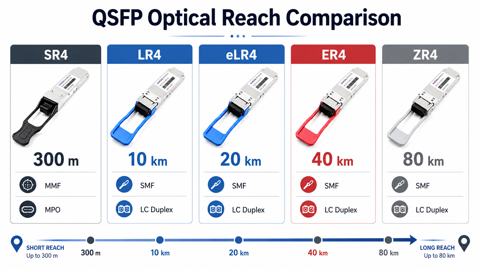
QSFP Module Types by Distance and Fiber
The second major decision after data rate is optical reach. QSFP variants are named according to the IEEE 802.3 standard they target. Understanding the naming convention prevents expensive mismatches.
| Variant |
Typical Distance
|
Fiber Type |
Connector |
Best For
|
| SR4 |
100 m
|
Multimode OM3/OM4 |
MPO/MTP |
Intra-rack, adjacent racks, short-reach DC
|
| CWDM4 |
2 km
|
Single-mode OS2 |
LC duplex |
Cost-optimized 100G DCI
|
| PSM4 |
500 m–2 km
|
Single-mode OS2 |
MPO/MTP |
Parallel 100G/400G links
|
| LR4 |
10 km
|
Single-mode OS2 |
LC duplex |
Metro DCI, telecom backhaul
|
| ER4 |
40 km
|
Single-mode OS2 |
LC duplex |
Extended metro, regional links
|
| ZR4 / ZR+ |
80+ km
|
Single-mode OS2 |
LC duplex |
Long-haul, coherent-capable links
|
The rule is simple: match the reach suffix to the physical distance and confirm the connector type before ordering cable assemblies. A QSFP module with an MPO connector cannot plug into an LC patch panel without a breakout or fan-out cable.
Parallel vs. Wavelength-Division Variants
SR4, DR4, and PSM4 are parallel optics. They use one fiber per lane, so a 4-lane module needs an MPO-12 cable with eight active fibers plus four spares. LR4, ER4, CWDM4, and FR4 are wavelength-division variants. They multiplex four lanes onto two fibers using different wavelengths, so they use LC duplex connectors.
That distinction drives cabling decisions. Parallel optics simplify module design but require MPO/MTP infrastructure. WDM variants use standard duplex fiber but require more complex optical assemblies.
QSFP vs SFP: When to Choose Quad Over Single-Lane
SFP, SFP+, and SFP28 are single-lane form factors. They are ideal for access-layer connections, server NICs, and low-density switches where flexibility and low cost per port matter. QSFP modules trade some of that flexibility for density and throughput.
Choose QSFP when:
- •You need 40G, 100G, 200G, or 400G in a single port.
- •Port density in the switch faceplate is limited.
- •Aggregation or spine-layer bandwidth is the bottleneck.
- •Breakout cabling can split one QSFP port into four lower-speed links.
Choose SFP when:
- •Most devices operate at 1G, 10G, or 25G.
- •You want the lowest cost per low-speed port.
- •Mix-and-match transceiver types across many ports is important.
Many modern leaf switches combine SFP28 access ports with QSFP28 uplink ports, giving engineers both flexibility and density in one chassis.
QSFP Cables and Connectivity
Not every QSFP link uses a standalone transceiver and fiber jumper. For short reaches inside racks or between adjacent racks, Direct Attach Copper (DAC) and Active Optical Cable (AOC) assemblies are often cheaper and simpler.
DAC Cables
DAC cables integrate the QSFP connector and copper cable into one passive or active assembly. They are cost-effective for links up to about 3–5 meters. Passive DAC relies on host equalization and works best for very short intra-rack connections. Active DAC adds signal conditioning to reach 7 meters or more.
AOC Cables
AOC cables embed optical transceivers at each end of a factory-terminated fiber cable. They support longer distances than DAC, typically up to 100 meters, and eliminate the need for separate transceivers and patch cords. AOCs are popular for structured data center cabling between racks.
Breakout Cables
Breakout cables split one QSFP port into multiple lower-speed ports:
- •QSFP+ 40G → 4 × 10G SFP+
- •QSFP28 100G → 4 × 25G SFP28
- •QSFP-DD 400G → 4 × 100G QSFP28 or 8 × 50G SFP56
The Breakout cabling helps maximize switch port utilization. A single 100G QSFP28 spine port can fan out to four 25G leaf switches, delaying the need for a full 100G leaf upgrade.
QSFP Compatibility and Vendor Considerations
Compatibility is where many QSFP deployments succeed or fail. A module may be electrically correct and optically correct, but if the switch refuses to recognize it, the port stays down.
MSA vs. OEM-Coded Modules
MSA-compliant modules follow the industry-standard form factor and electrical interface. They are generally interchangeable across vendors. OEM-coded modules add vendor-specific EEPROM data that some switch platforms require before enabling the port. Cisco, Arista, Juniper, NVIDIA/Mellanox, and Dell each have their own encoding expectations.
Third-party suppliers, including Ascent Optics, often offer modules pre-coded for specific switch platforms. That approach delivers MSA interoperability plus OEM recognition. Always verify the compatibility matrix before purchasing in volume.
Switch ASIC and Firmware Requirements
Newer QSFP generations require matching SerDes capability on the switch ASIC. For example:
- •QSFP28 requires 25G NRZ SerDes.
- •QSFP56 requires 50G PAM4 SerDes.
- •QSFP112 requires 100G PAM4 SerDes.
- •QSFP-DD requires 50G or 100G PAM4 SerDes across eight lanes.
Switch firmware must also support the module’s management interface, typically CMIS (Common Management Interface Specification) for QSFP-DD and newer modules.
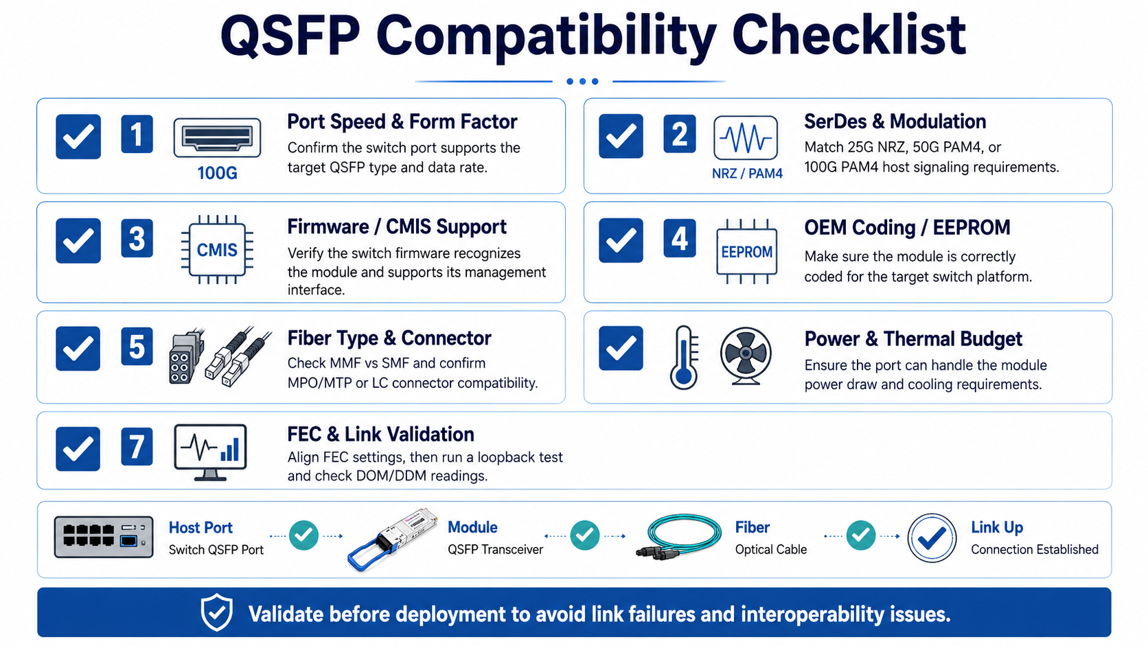
Validation Checklist Before Deployment
Before plugging in a batch of QSFP modules, confirm:
- •Port speed and modulation match the module.
- •Switch firmware recognizes the module profile.
- •Fiber type and connector match the module variant.
- •Power and thermal budgets accommodate high-speed modules.
- •FEC settings align between the host and the module for PAM4 links.
Running a short loopback test and checking DOM readings before production cutover catches many common issues.
Conclusion
As network bandwidth requirements continue to grow, QSFP modules remain at the center of modern optical connectivity. From legacy 40G QSFP+ deployments to today’s 100G QSFP28, 200G QSFP56, and emerging 400G and 800G QSFP-DD solutions, the QSFP ecosystem provides a scalable path for data centers, cloud networks, AI clusters, and high-performance computing environments.
Choosing the right QSFP module involves more than matching a port speed. Network architects must also consider fiber type, transmission distance, breakout requirements, power consumption, thermal constraints, and platform compatibility. Understanding the differences between SR, DR, FR, LR, and other optical variants helps ensure reliable performance while avoiding unnecessary infrastructure costs.
As AI workloads, cloud services, and east-west traffic continue to expand, demand for higher-density optical interconnects will only increase. Whether you are upgrading an existing 40G network, deploying new 100G infrastructure, or planning for 400G and 800G architectures, selecting the appropriate QSFP transceiver is a critical step toward building a scalable and future-ready network.
Explore Ascent Optics’ complete portfolio of QSFP transceivers to find the right solution for your application, from short-reach data center links to long-distance enterprise and telecom deployments.
Frequently Asked Questions
What is a QSFP module?
A QSFP module is a compact, hot-pluggable optical transceiver that uses four parallel lanes to transmit high-speed data over fiber optic cable. It is widely used in data centers, telecom networks, and high-performance computing.
What is the difference between QSFP and QSFP28?
QSFP usually refers to the 40G QSFP+ generation with four 10 Gbps lanes. QSFP28 supports 100G with four 25 Gbps lanes. They share the same mechanical cage, but QSFP28 ports can accept QSFP+ modules, while the reverse is generally not true.
Can I use QSFP28 in a QSFP+ port?
No. The modules fit the same cage, but the electrical interfaces differ. A QSFP+ port typically cannot negotiate the 25 Gbps lanes used by QSFP28.
What fiber do QSFP modules use?
QSFP modules use multimode fiber for short reaches (SR4/SR8) and single-mode fiber for longer reaches (LR4, ER4, ZR4, DR4, FR4). The specific fiber type depends on the optical variant.
How far can QSFP modules transmit?
Distances range from 100 meters over multimode fiber for SR4 variants to 80 kilometers or more over single-mode fiber for ZR/ZR+ variants.
Post Views: 1,065