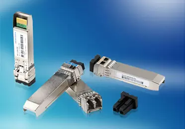
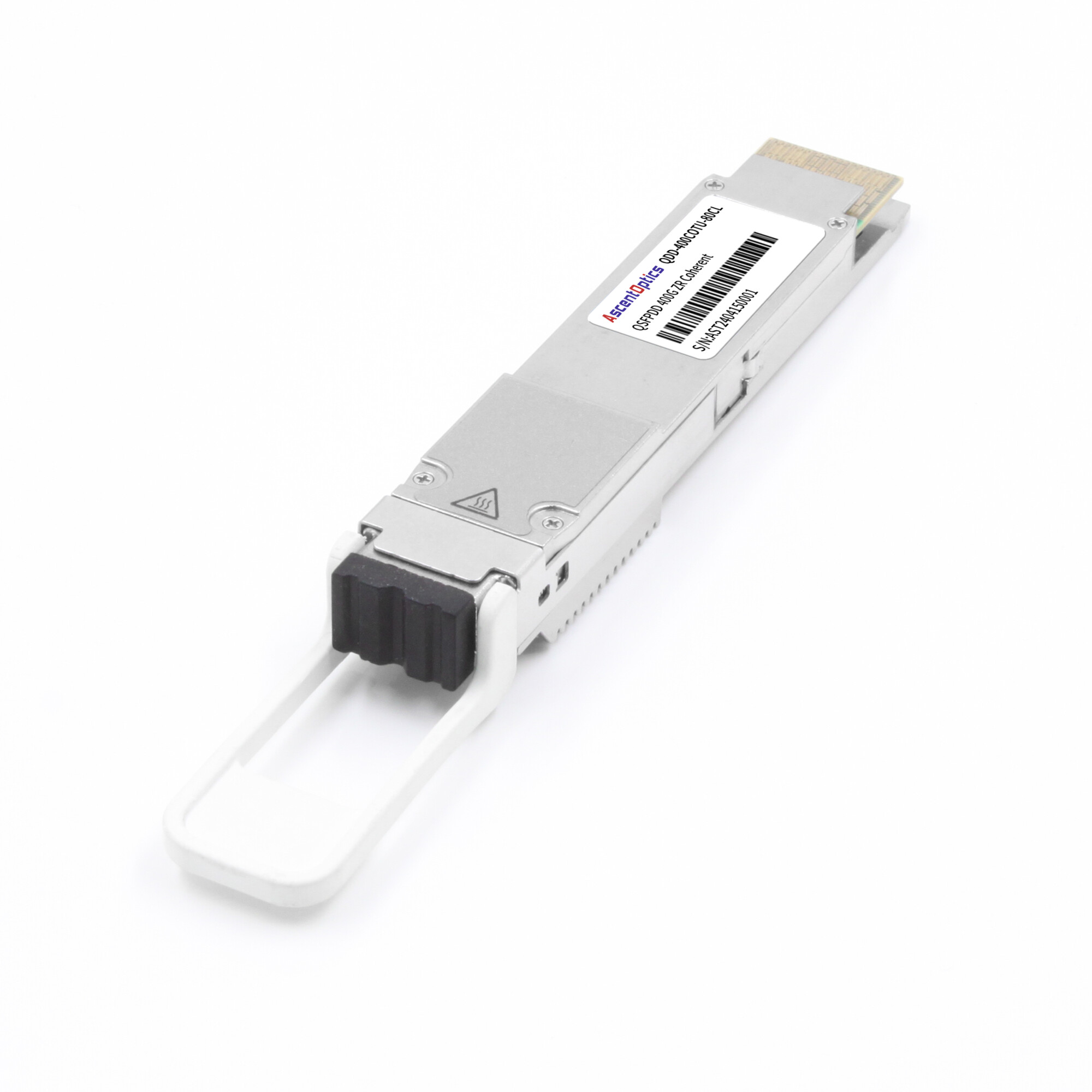
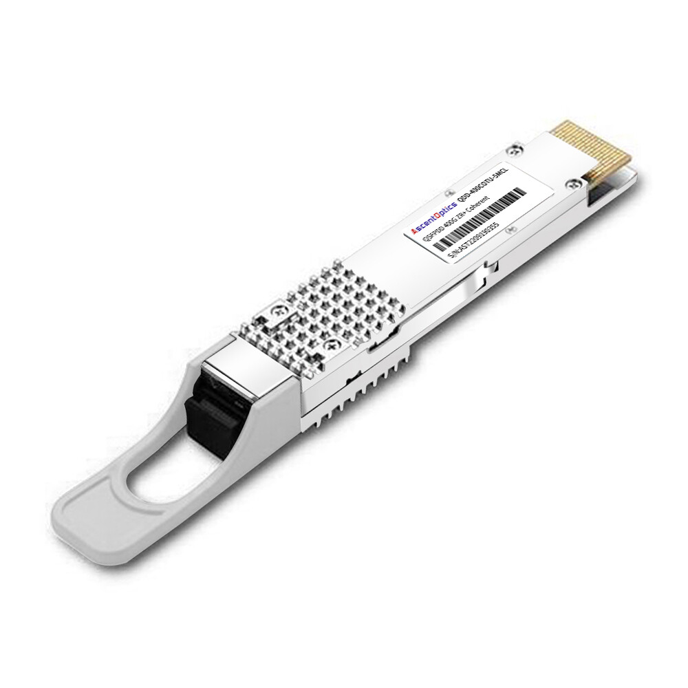
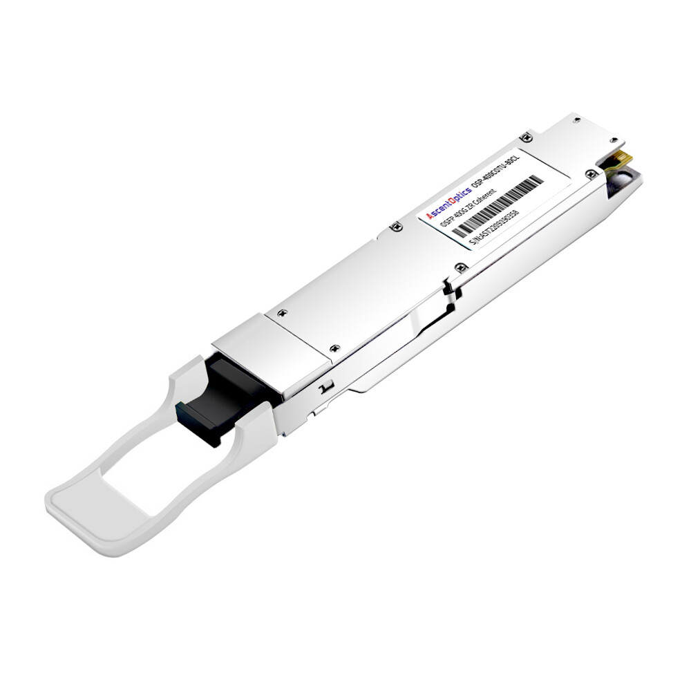
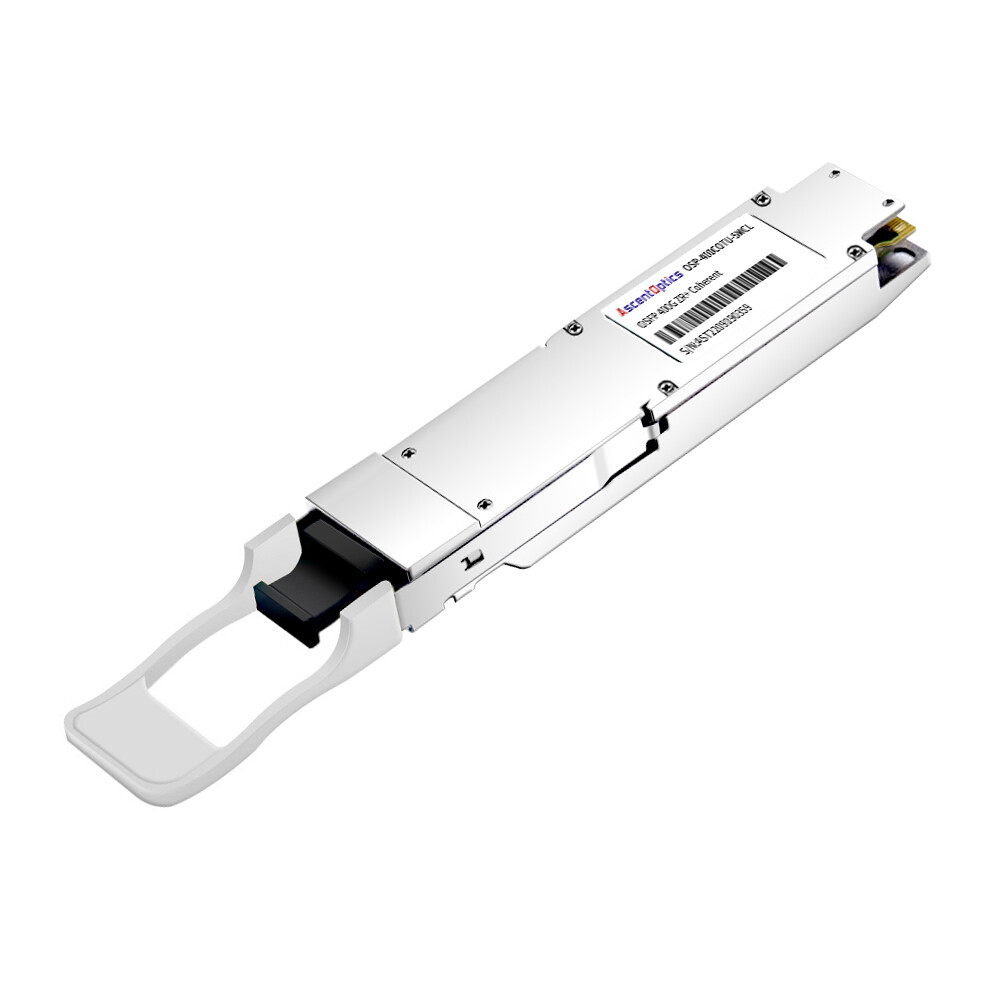
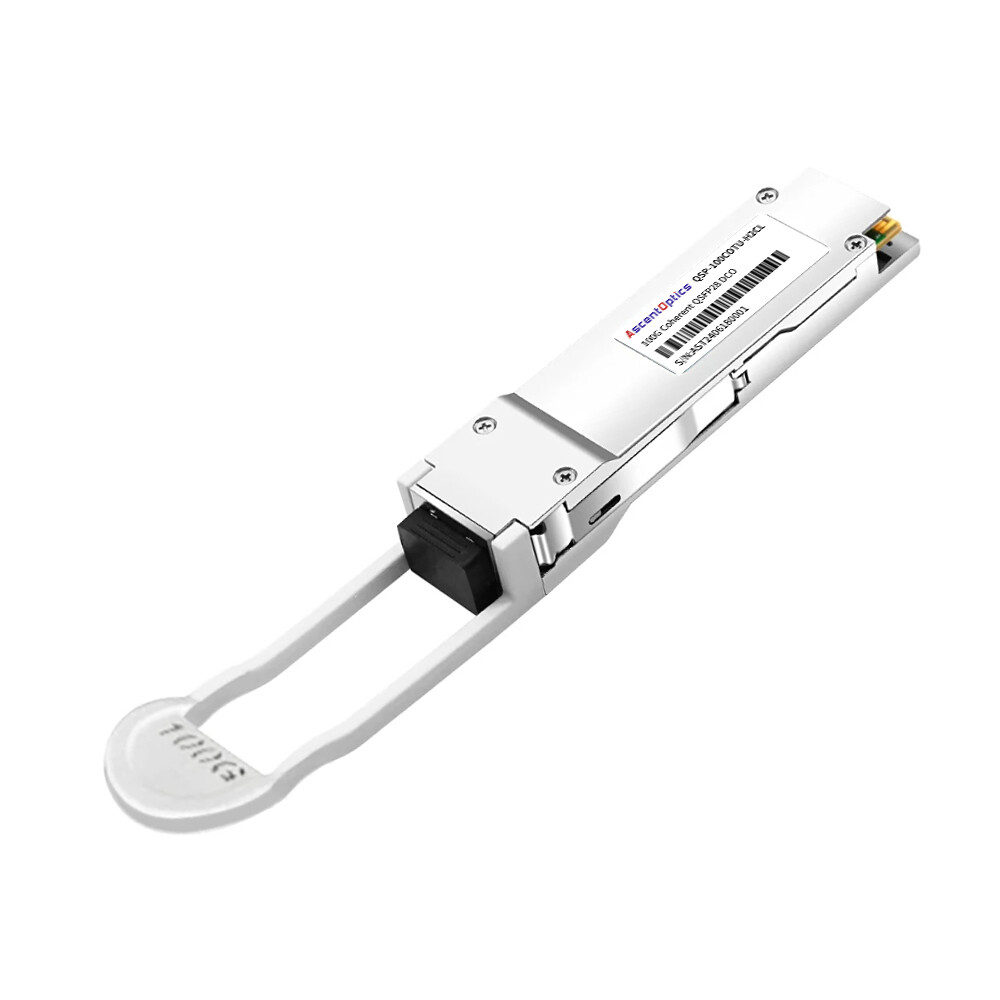
Coherent optical modules are widely used in metro, DCI, and long-haul optical networks where high capacity and extended transmission distance are required. Troubleshooting these modules requires engineers to evaluate not only optical power, but also signal quality, OSNR, DSP status, FEC performance, and fiber impairments.
This guide focuses on common root causes—such as signal degradation, chromatic dispersion, nonlinear effects, and laser aging—and integrates optical power monitoring, constellation analysis, and FEC error statistics to help engineers systematically pinpoint issues, reduce the mean time to repair (MTTR), and ensure the reliability and performance of long-haul transmission.
How Coherent Module Troubleshooting Differs from Traditional Optics
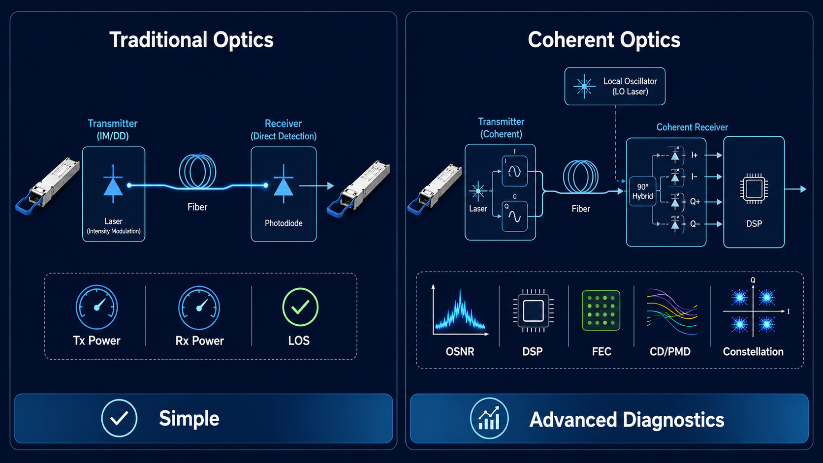
Traditional intensity-modulation/direct-detection (IM/DD) transceivers are relatively simple devices. You check Tx power, Rx power, and if both look normal but the link is down, you swap the module. The diagnostic surface area is small.
Coherent optical modules operate on an entirely different principle. Coherent receivers mix the incoming optical signal with a local oscillator and use high-speed electronics and DSP algorithms to recover amplitude, phase, and polarization information. This enables higher-order modulation formats — QPSK, 8QAM, 16QAM, 64QAM — but it also introduces failure domains that do not exist in IM/DD optic
When you troubleshoot a coherent link, you are not just checking whether light arrives at the far end. You are checking whether the DSP can lock onto that light, whether the phase recovery loop is stable, whether chromatic dispersion and polarization mode dispersion are within compensation range, whether the FEC decoder is keeping up with the pre-FEC error rate, and whether the OSNR — not just the raw Rx power — is sufficient for the modulation format in use.
Key telemetry parameters commonly available on coherent modules include: (and every engineer should monitor):
- •Pre-FEC BER and Post-FEC BER: The single most important indicators of link health. Pre-FEC BER tells you about raw channel quality; post-FEC BER tells you whether the error correction is coping.
- •OSNR estimate: Coherent performance is OSNR-sensitive. A link with good Rx power but poor OSNR will still produce errors.
- •Q-factor and Q-margin: How much margin exists before the link hits the FEC correction limit.
- •Chromatic Dispersion (CD) and Differential Group Delay (DGD): Must stay within the DSP’s compensation envelope.
- •Frequency offset: Mismatch between transmitter and receiver local oscillator frequencies. Excessive offset overwhelms the carrier phase recovery loop.
- •DSP lock status and training duration: If the DSP cannot converge during training, the link will never come up — regardless of optical power.
- •Error Vector Magnitude (EVM): Quantifies modulation quality; elevated EVM indicates impairment before the FEC stage.
Understanding these parameters is the foundation of coherent optical module troubleshooting. Without them, you are diagnosing in the dark.
The 7-Step Coherent Link Troubleshooting Methodology
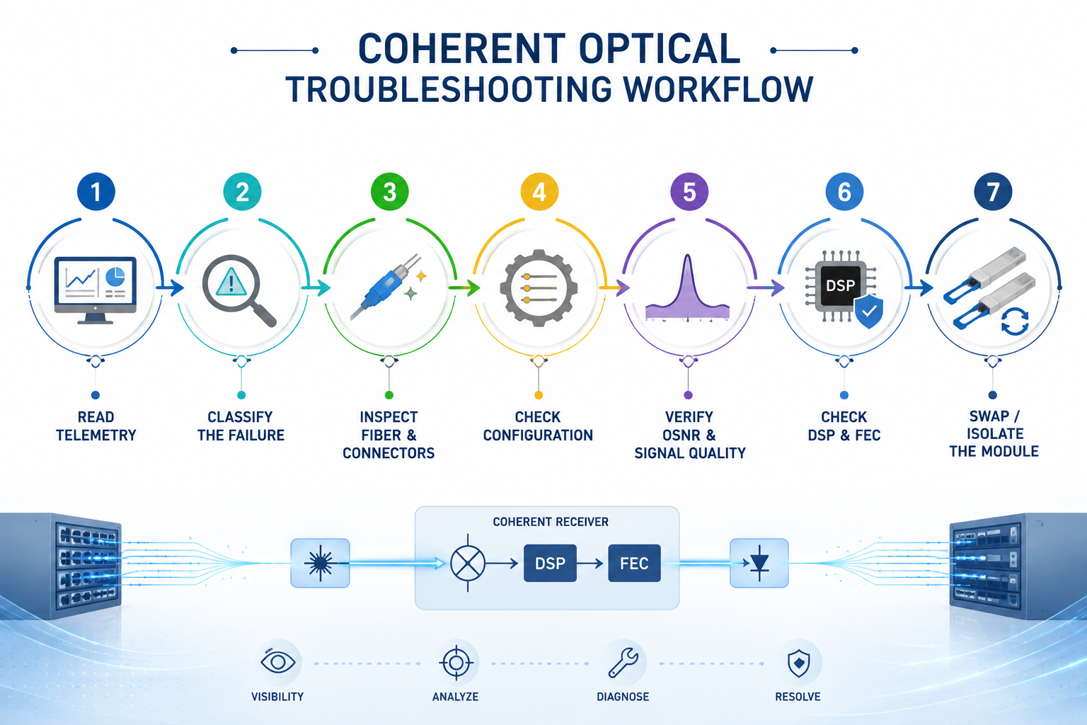
Every coherent link failure falls into one of three categories: the link never comes up, the link comes up but is unstable, or the link is up, but performance is degrading. The methodology below works for all three. Follow the steps in order — each one builds on the information gathered in the previous step.
Step 1: Read DOM and DSP Telemetry Before Touching Anything
The most common mistake engineers make is reaching for the fiber cleaner before looking at the telemetry. Do not do this. Module telemetry can often narrow the fault domain much faster than starting with physical inspection.
What to check immediately:
- •Module state and datapath state: Is the module recognized? Is the datapath initialized?
- •Tx power and Rx power: Are both within the datasheet operating range? Is there a sudden drop from the baseline?
- •Temperature, voltage, bias current: Are these within normal range? Has anything changed recently?
- •Alarm summary: Are there coherent-specific alarms? LOS, LOF, LOM, OOF, OOM? FEC degradation? DSP lock failure?
- •Quick classification rule: If Tx and Rx power are normal but the DSP reports loss of lock, check configuration compatibility first, followed by OSNR, signal impairments, and module health. If Rx power is low or absent — suspect physical layer or remote Tx failure. If Rx power is normal but pre-FEC BER is high — suspect OSNR deficit, nonlinear impairment, or fiber aging.
Step 2: Classify the Failure Mode
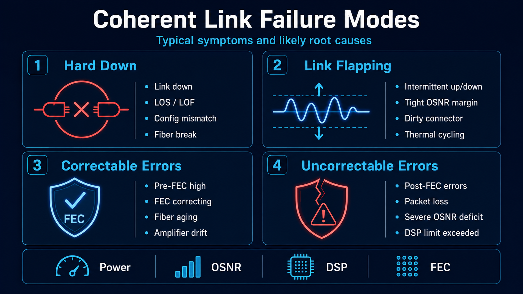
Before you start changing anything, categorize what you are dealing with. Each failure class points to a different diagnostic path.
| Failure Class |
Symptoms |
Most Likely Root Cause |
| Hard down — no link |
Port administratively up, operationally down; possible LOS/LOF |
Configuration mismatch, DSP failure, physical fiber break |
| Link flapping |
Link goes up and down intermittently |
OSNR margin too tight, connector contamination, thermal cycling |
| Degraded — high correctable errors |
Link up, pre-FEC BER elevated, FEC correcting errors |
Fiber aging, amplifier drift, increasing connector loss |
| Degraded — uncorrectable errors |
Link up, post-FEC BER non-zero, packet loss |
Severe OSNR deficit, nonlinear penalty, DSP compensation exceeded |
| Intermittent errors |
Errors correlate with time of day or environmental changes |
Thermal cycling, day/night fiber expansion, amplifier gain drift |
Decision rule: If the link was working previously and suddenly failed, investigate what changed — a maintenance window, a new channel added to the DWDM system, a firmware upgrade, a fiber path change. If it is a new deployment that never worked, start with configuration validation (Step 4).
Step 3: Physical Layer Inspection
Even in the DSP era, connector contamination remains the single most common root cause of coherent link degradation. Connector contamination can introduce significant insertion loss and return loss, and even a relatively small additional loss can be important on a coherent link operating with limited OSNR margin.
Inspect, clean, inspect: Use a fiber inspection scope on every connector in the path — at the module faceplate, at the patch panel, at the WDM mux/demux port. Follow the inspect-clean-inspect loop until the end-face is pristine. Never skip the inspection step and assume cleaning fixed it.
Verify with an optical power meter and light source: Measure Tx output power at the module faceplate. Measure Rx input power at the far end. Calculate total link attenuation. Compare against the link budget.
Run an OTDR trace: If attenuation is higher than expected, an OTDR trace will locate the problem — a bad splice, a tight bend, a cracked connector. For coherent links, also check return loss; poor return loss creates reflections that degrade DSP performance. If excessive attenuation is suspected, an OTDR can help locate fiber breaks, splice loss, or abnormal events. Return-loss measurements may also be useful when reflections are suspected.
Step 4: Validate Configuration on Both Ends
Configuration mismatch is the most common reason a new coherent link never comes up — and it is almost always the last thing checked because engineers assume “we configured both ends the same way.”
Coherent modules require far more configuration alignment than traditional optics. The following parameters should be compatible between the two link partners and, where applicable, configured consistently.
| Parameter |
What to Verify |
Mismatch Symptom |
| Modulation format |
QPSK, 8QAM, 16QAM must match |
DSP fails to lock or very high pre-FEC BER |
| Baud rate |
Must be identical both ends |
DSP training fails |
| FEC mode |
oFEC, cFEC, eFEC — must be the same type |
FEC decoder cannot correct; post-FEC errors |
| DAC rate/pulse shaping |
Nyquist shaping parameters |
Inter-symbol interference, elevated BER |
| Channel frequency |
ITU grid channel, center frequency |
Wavelength mismatch; receiver cannot detect signal |
| Grid spacing |
50 GHz, 75 GHz, 100 GHz, flex-grid |
Filter passband mismatch |
| Framing format |
ZR, ZR+, OpenROADM |
Framing mismatch; link fails to initialize |
Real-world scenario: A cloud provider deploying 400G-ZR+ links between three colocation sites used modules from two different vendors. Vendor A defaulted to oFEC. Vendor B shipped with cFEC as the factory default. Both were configured for “400G-ZR+” on the router. The link would not come up. The DSPs tried to train for 30 seconds and gave up. The fix was a single configuration change — but it took two days to find because the FEC mode mismatch did not produce a clear alarm; it just reported “DSP training timeout.”
Step 5: OSNR and Signal Quality Verification
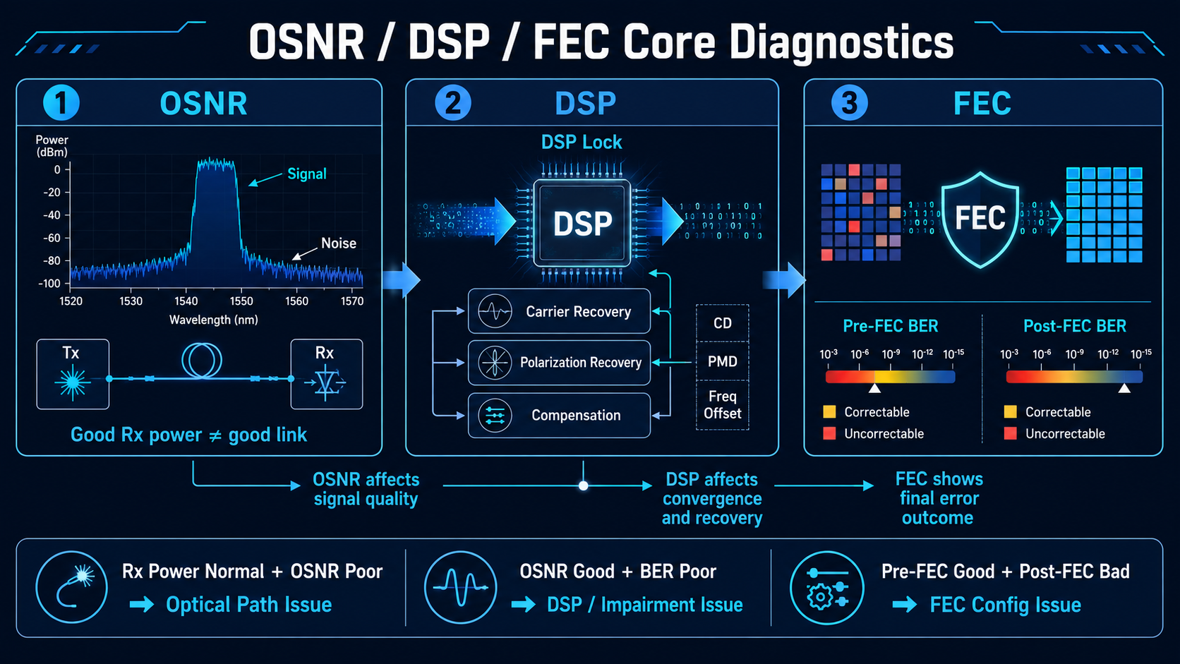
OSNR is the primary figure of merit for coherent link performance. Unlike IM/DD optics, where received power is the dominant metric, coherent links can have excellent Rx power but terrible OSNR — and terrible performance.
OSNR measurement: Use an optical spectrum analyzer (OSA) or the module’s built-in OSNR estimate. For 400G coherent links using 16QAM modulation, OSNR should typically be 20 dB or higher for stable post-FEC error-free operation. The required OSNR depends on the modulation format, baud rate, FEC scheme, implementation, and measurement reference. Always compare the measured value with the module’s specified OSNR requirement rather than applying a universal threshold. Check the module datasheet for the specific required OSNR at your modulation format and baud rate.
If OSNR is below threshold:
- •Verify amplifier gain settings. An amplifier that was correctly set during commissioning may have drifted.
- •Check for excess connector or splice loss that was not accounted for in the link budget.
- •Inspect WDM filter passbands — a misaligned filter adds insertion loss that reduces OSNR.
- •Rebalance channel powers in multi-channel DWDM systems.
The OSNR vs. launch power trade-off: There is an optimal launch power for every coherent link. Too low, and ASE noise from amplifiers dominates. Too high, and fiber nonlinearities — self-phase modulation, cross-phase modulation, four-wave mixing — generate nonlinear interference that looks like noise to the receiver. The optimal point is found by sweeping launch power and measuring OSNR or pre-FEC BER at each step. If a link was recently re-engineered and performance degraded, check whether launch power was changed.
If OSNR is good but BER is poor: The problem is not an OSNR problem. Move to Step 6 — suspect DSP convergence issues, phase noise, CD/PMD exceeding compensation limits, or a hardware fault in the module itself.
Step 6: DSP and FEC Diagnostic Deep Dive
When the physical layer checks out and the OSNR is adequate, the DSP is where you look next. The DSP is the “brain” of the coherent module — it compensates for impairments, recovers the carrier, demultiplexes polarizations, and feeds the FEC decoder. If any of these functions fails, the link fails.
DSP lock status: If the DSP reports loss of lock (LOL) or has not completed training, check the configuration alignment first (Step 4). Then verify that the received signal impairments — CD, PMD, frequency offset — are within the DSP’s specified compensation range. Most modern coherent DSPs can compensate tens of thousands of ps/nm of CD, but not all spans are within that envelope.
Pre-FEC vs. Post-FEC BER:
- •Pre-FEC BER below 1×10⁻³ and post-FEC BER clean → link is healthy; monitor trend.
- •Pre-FEC BER below 1×10⁻³ but post-FEC uncorrected words increasing → FEC mode mismatch or FEC threshold misconfiguration.
- •Pre-FEC BER above 1×10⁻² → link is impaired; check OSNR, CD, DGD, and nonlinear penalties.
- •Pre-FEC BER fluctuating with no clear pattern → suspect polarization-dependent effects or intermittent connector issues.
Loopback testing for fault isolation: Coherent modules support multiple loopback modes. Depending on the module and platform, available loopback modes may include DSP, optical, line, or host loopback. Use them systematically:
- •DSP loopback(internal to the DSP): Tests the DSP and host interface — if this passes, the module’s electronics are functional.
- •Optics loopback(internal to the module): Tests the full transmit-to-receive path inside the module — if this passes, the module itself is good.
- •Line loopback(toward the fiber): Loops the signal back at the line interface — tests the module plus the near-end fiber plant.
- •Host loopback(toward the host): Tests the host interface and client-side optics.
Work from the inside out: DSP loopback → optics loopback → line loopback. Each passing test narrows the fault domain.
Step 7: Fault Isolation and Swap Testing
After working through the diagnostic steps above, you should have a clear hypothesis. Now confirm it.
The swap test protocol:
- 1. Replace the suspect module with a known-good module of the same type and firmware revision.
- 2. If the link recovers → the original module was faulty. Quarantine it for RMA.
- 3. If the link does not recover → the problem is in the fiber plant, configuration, or far-end equipment. Return the original module to its slot.
Telemetry-based probability scoring: Before swapping, check whether the fault signature points to the module or the path:
| If you see… |
Probability points to… |
Because… |
| Tx power drift + bias current drift + rising FEC errors |
Module fault (laser aging) |
All three track together when the laser degrades |
| Rx power drop + stable Tx + consistent FEC deterioration |
Fiber/path fault |
The transmitter is fine; something is attenuating the signal |
| FEC errors rising + no power change + no temperature drift |
Coherent-specific effect |
Could be DSP calibration drift, polarization issue, or amplifier noise |
| Both ends show simultaneous Rx power drop |
Fiber path event |
Shared fiber-path, WDM, amplifier, or system-level event |
When to stop troubleshooting and replace: Consider replacement when the module shows persistent performance degradation, abnormal laser bias-current growth, declining output power, or other indicators of aging. The vendor’s specified lifetime and operating conditions should be used as the primary reference. Coherent lasers have finite lifetimes, and preventive replacement during a maintenance window is less costly than emergency replacement during an outage.
Common Coherent Optical Module Failure Patterns and Solutions
The following failure patterns represent the cases most frequently encountered in production coherent deployments. Each includes the telltale telemetry signature and the targeted remediation.
Link Fails to Come Up — No Link Light
Telltale signature: Port administratively up, operationally down. DSP reports training timeout or loss of lock. No LOS alarm on the receiver.
Most likely causes (in order of probability):
- 1. Configuration mismatch between the two ends — FEC mode, modulation format, or channel frequency
- 2. DSP firmware version incompatibility between modules from different vendors
- 3. Wavelength plan error — the transmitter is on the wrong ITU channel
- 4. Physical fiber break or disconnected patch cord (less common, but always worth checking first)
First action: Dump the active configuration from both modules and compare every parameter line by line. This can quickly identify configuration-related failures before more time-consuming physical troubleshooting begins.
Link Comes Up but Flaps or Is Unstable
Telltale signature: Link transitions between up and down states. DSP lock is achieved but lost intermittently. Pre-FEC BER spikes correlate with link-down events.
Most likely causes:
- •OSNR margin too tight — the link is operating within 1-2 dB of the FEC limit
- •Connector contamination causing intermittent insertion loss variation
- •Thermal cycling — module temperature swings from day/night or HVAC cycling
- •Incorrect channel plan causing adjacent-channel crosstalk at specific times
First action: Trend OSNR, pre-FEC BER, and module temperature over 24 hours. Look for correlation between environmental changes and link events. If OSNR is marginal, investigate whether amplifier gain can be increased or whether a lower-modulation-order format (e.g., QPSK instead of 16QAM) can be used to improve margin.
High FEC Errors with Link Up
Telltale signature: Link is stable and passing traffic, but pre-FEC BER is elevated and FEC-corrected error counters are incrementing. No uncorrected words yet, but trending upward.
Most likely causes:
- •Fiber aging or gradual connector degradation
- •Amplifier gain drift over time
- •Nonlinear penalty from excessive launch power
- •CD or PMD approaching the DSP compensation limit
First action: Compare current telemetry against the commissioning baseline. If all metrics show a gradual trend in the same direction, schedule preventive maintenance. If one metric changed abruptly, investigate a specific event — a recent maintenance action, a new DWDM channel added, or a patch panel reorganization.
Performance Degrades Slowly Over Months
Telltale signature: All telemetry parameters are within threshold, but everything shows a slow, consistent drift in the wrong direction. Pre-FEC BER up 15% from baseline. OSNR down 1.5 dB. Module temperature up 3 °C.
Most likely causes:
- •Laser aging — gradual increase in bias current, decrease in output power, increase in phase noise
- •Connector contamination accumulation in a dusty environment
- •Amplifier slow degradation
- •Fiber plant changes from environmental factors (temperature, moisture)
First action: Establish a maintenance window to clean all connectors, re-measure the span loss, and re-baseline the link. If the module is approaching end-of-life, plan a proactive replacement.
Coherent-Specific Alarm Interpretation
Coherent modules expose a richer set of alarms than traditional optics. Understanding what each alarm means — and what it does not mean — speeds diagnosis considerably.
Transmitter-Side Alarms
| Alarm |
Meaning |
First Action |
| TX Loss of Alignment |
Signal alignment between DSP and optics lost on the transmit path |
Check module temperature; reset the port; if persistent, suspect hardware fault |
| TX CMU Loss of Lock |
Clock multiplier unit lost lock — timing reference failure |
Verify reference clock source; check for clock configuration errors |
| TX Reference Clock Loss of Lock |
External reference clock not detected or out of range |
Check clock input cabling and signal integrity |
Receiver-Side Alarms
| Alarm |
Meaning |
First Action |
| RX Demodulator Loss of Lock |
DSP cannot demodulate the received signal — the most critical coherent alarm |
Verify far-end Tx is active; check modulation format match; check OSNR |
| RX CDC Loss of Lock |
Clock and data recovery lost lock on client side |
Check client-side signal integrity and host interface |
| RX FEC Excessive Degrade |
Pre-FEC BER has reached or exceeded the FEC correction threshold |
Improve OSNR immediately; reduce span loss; consider modulation format downgrade |
| RX FEC Detected Degrade |
Pre-FEC BER has reached the signal degrade threshold (early warning) |
Schedule investigation; check OSNR, CD, connector condition |
| SF_BER |
Signal Fail threshold crossed (typically 1×10⁻⁵) |
Critical — link at risk of failure; immediate investigation required |
| SD_BER |
Signal Degrade threshold crossed (typically 1×10⁻⁷) |
Warning — link quality degrading; schedule maintenance |
Environmental Alarms
HI-TEMP, LO-TEMP, HI-VOLTAGE, and LO-VOLTAGE alarms indicate the module’s operating environment has exceeded safe limits. Coherent modules consume 18 to 25 W (for 400G-ZR+) and are thermally sensitive. Temperature-induced laser wavelength drift directly affects coherent performance. Verify fan tray operation, ensure blank panels fill empty slots for proper airflow, and confirm the ambient temperature is within specifications.
General-Purpose Diagnostic Tools
| Tool |
What It Tells You |
When to Use |
| Optical Spectrum Analyzer (OSA) |
Per-channel power, OSNR, wavelength accuracy |
OSNR investigation, channel plan verification |
| OTDR |
Span loss profile, splice loss, break location |
Fiber plant fault location |
| BERT (Bit Error Rate Tester) |
BER under controlled test patterns |
Module performance validation after repair |
| Fiber Inspection Scope |
Connector end-face contamination and damage |
Every physical layer investigation |
| Coherent Performance Analyzer |
Modulation quality, EVM, phase noise |
Advanced DSP-layer diagnostics |
Preventive Monitoring: Catching Problems Before They Become Outages
The difference between a 5-minute fix and an 18-hour outage is often a monitoring strategy that catches degradation before it becomes failure.
Establish Performance Baselines
After every coherent link is commissioned and confirmed stable, capture a “known-good” telemetry baseline:
- •OSNR (per direction)
- •Pre-FEC BER and Post-FEC BER
- •Q-factor and Q-margin
- •Tx power, Rx power, bias current, temperature
- •Chromatic dispersion and DGD estimates
- •FEC uncorrected word count (should be zero)
Store these baselines somewhere accessible — a network monitoring system, a configuration management database, or a simple spreadsheet. The baseline is your reference for every future troubleshooting session.
Set Trend-Based Alerts, Not Just Static Thresholds
Static threshold alerting — “alert when Rx power drops below -15 dBm” — catches hard failures but misses slow degradation. By the time a static threshold fires, you may already be in an outage window.
Trend-based rules that catch problems earlier:
- •Drift persistence: Alert only if a parameter drifts consistently in one direction for 30 to 60 minutes. This filters out transient fluctuations.
- •Cross-metric correlation: Require at least two metrics to move in a consistent direction before alerting. A single Rx power dip with no BER change is probably a measurement artifact.
- •Change-point detection: Alert on abrupt level shifts — the kind that happen when a connector is disturbed, or a patch cord is replaced.
- •FEC early warning: Configure FEC degrade thresholds at a conservative level so the NOC has hours or days of warning before uncorrected errors appear.
Commissioning Validation Checklist
Before declaring any coherent link “in service,” run through this checklist. The 30 minutes it takes can prevent days of troubleshooting later.
Configuration
- •Modulation format, baud rate, FEC mode identical on both ends
- •Channel frequency and grid spacing match the DWDM plan
- •Tx power targets set per the link budget, not at factory defaults
- •Framing format (ZR, ZR+, OpenROADM) consistent
Optical Path
- •All connector end-faces inspected and cleaned
- •End-to-end insertion loss measured and within budget
- •OTDR trace captured and filed for future reference
- •Return loss measured; within specification
Signal Quality
- •OSNR measured with OSA or module estimate; ≥ required minimum for modulation format
- •Pre-FEC BER below 1×10⁻³ under idle trafficPre-FEC BER remains below the module/platform’s specified threshold.
- •Post-FEC BER error-free after 15 minutes of PRBS testingNo uncorrected FEC errors are observed during the defined validation period.
- •OSNR and BER stable over a minimum 1-hour soak period
DSP and Link Behavior
- •DSP lock achieved within expected training duration
- •CD and DGD within module compensation range
- •Frequency offset stable and within tolerance
- •Loopback tests pass: DSP → optics → line (as applicable)
Thermal and Power
- •Module temperature stable within 10 to 35 °C operating range
- •Power consumption within datasheet specification
- •No HI-TEMP, LO-VOLTAGE, or other environmental alarms active
Monitoring Readiness
- •Telemetry parameters streaming to NMS/observability platform
- •Performance monitoring thresholds configured
- •Commissioning baseline captured and stored
- •Escalation runbook updated with link-specific details
Conclusion
Coherent optical modules have transformed long-haul and metro networking — but they have also transformed the troubleshooting landscape. The diagnostic surface area is larger: DSP lock, FEC margin, OSNR, phase noise, polarization tracking, and chromatic dispersion all sit alongside the traditional concerns of power, temperature, and physical connectivity.
FAQ About Coherent Optical Module Troubleshooting
1. What should I check first when a coherent optical link fails?
Start with module telemetry, including Tx/Rx power, alarms, DSP lock status, temperature, and FEC counters.
2. Can a coherent link have normal Rx power but still perform poorly?
Yes. Good Rx power does not guarantee good signal quality. Low OSNR, DSP impairments, or high BER can still cause link degradation.
3. What does high pre-FEC BER indicate?
High pre-FEC BER usually indicates poor channel quality caused by OSNR degradation, fiber impairments, nonlinear effects, or connector loss.
4. What does non-zero post-FEC BER mean?
It means the FEC decoder can no longer fully correct the received errors and the link may experience packet loss or instability.
5. What should I check if the DSP cannot lock?
Verify modulation format, baud rate, FEC mode, channel frequency, OSNR, CD/PMD, and frequency offset.
6. How can I determine whether the module or fiber path is faulty?
Replace the suspect module with a known-good unit. If the link recovers, the module is likely faulty. If not, investigate the fiber path, configuration, or remote equipment.
7. Which tools are commonly used for coherent link troubleshooting?
Common tools include an optical spectrum analyzer (OSA), OTDR, fiber inspection scope, optical power meter, BERT, and coherent performance analyzer.
8. When should a coherent optical module be replaced?
Consider replacement when the module shows persistent performance degradation, abnormal laser bias-current growth, declining Tx power, or recurring hardware-related faults.
Post Views: 1,397