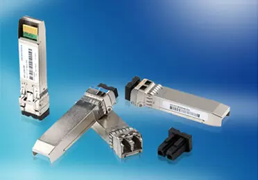
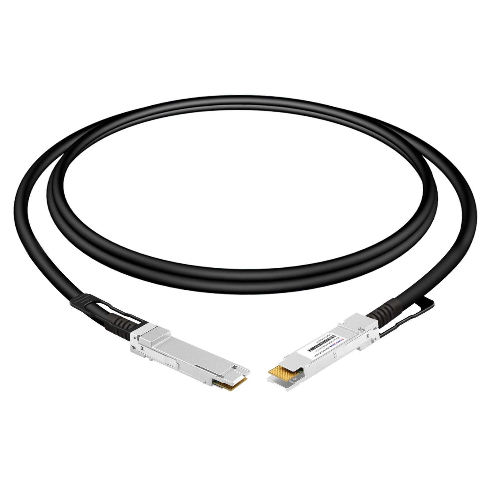
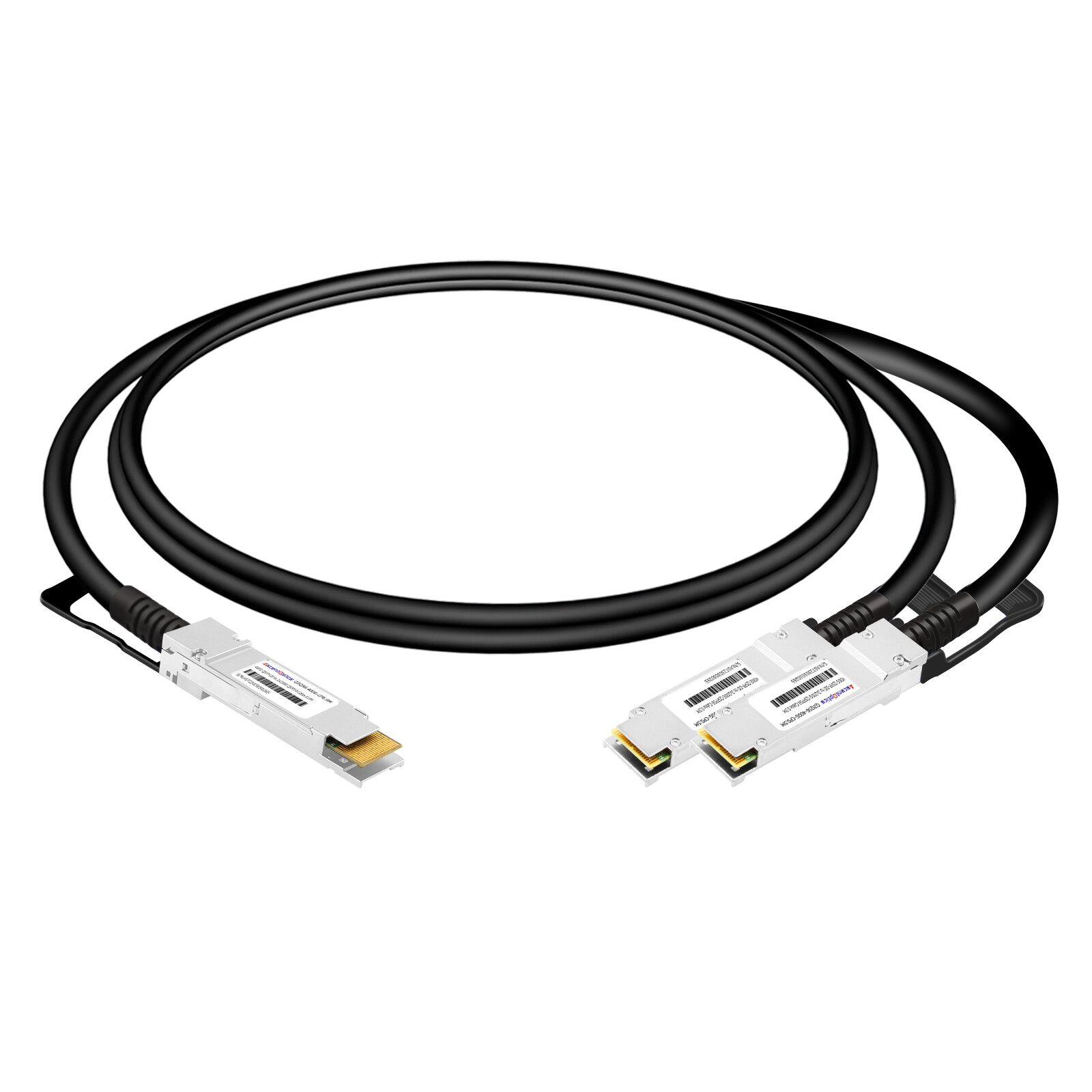
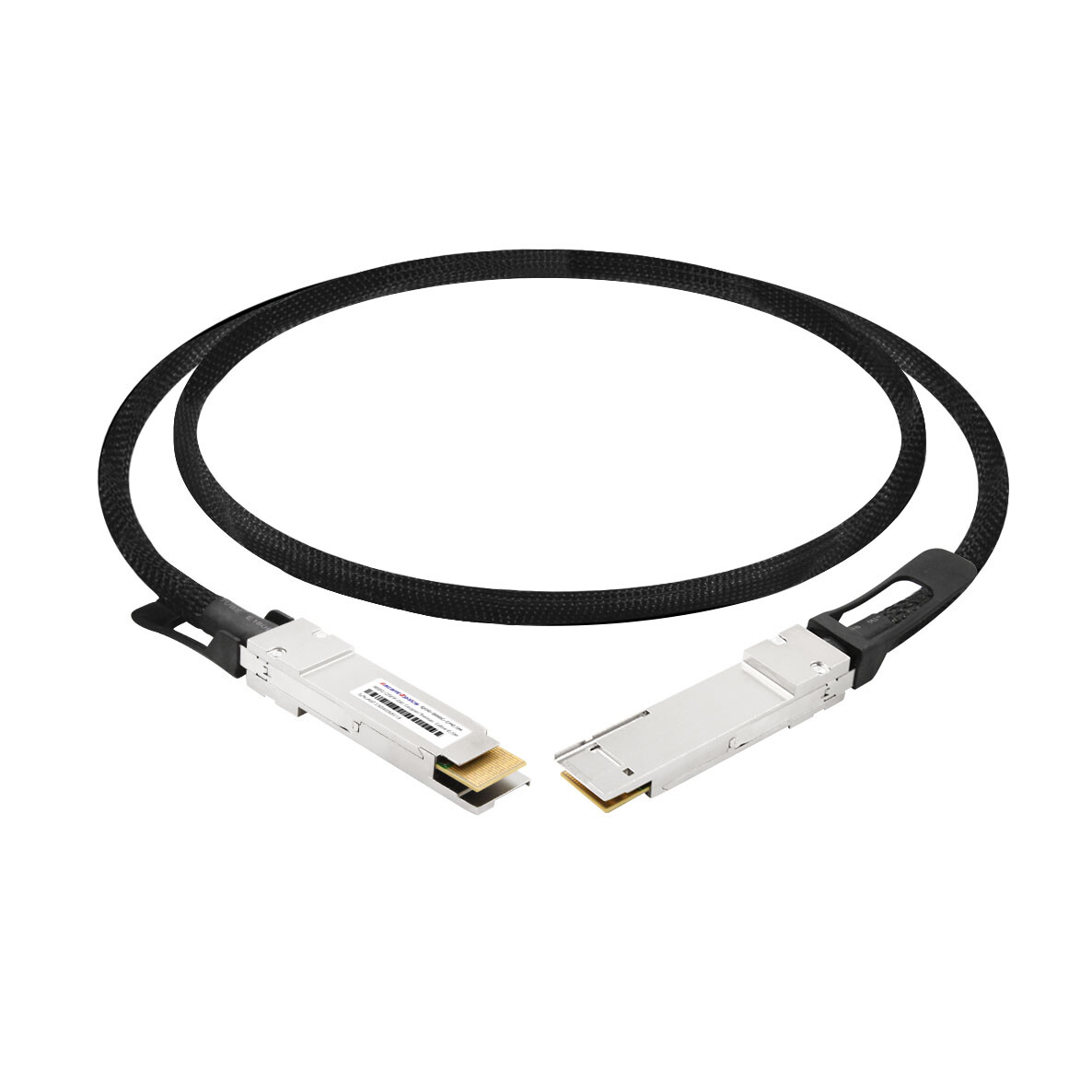
QSFP-DD direct attach copper (DAC) cables provide short-reach, high-density electrical connectivity for compatible 400GbE and 800GbE switch and network interface ports. Passive DAC assemblies offer very low cable-side power consumption and typically serve short in-rack links, while active copper options can extend reach. Actual supported length, lane rate, and interoperability depend on the cable design, host platform, and Ethernet PHY.
What Is a QSFP-DD DAC Cable?
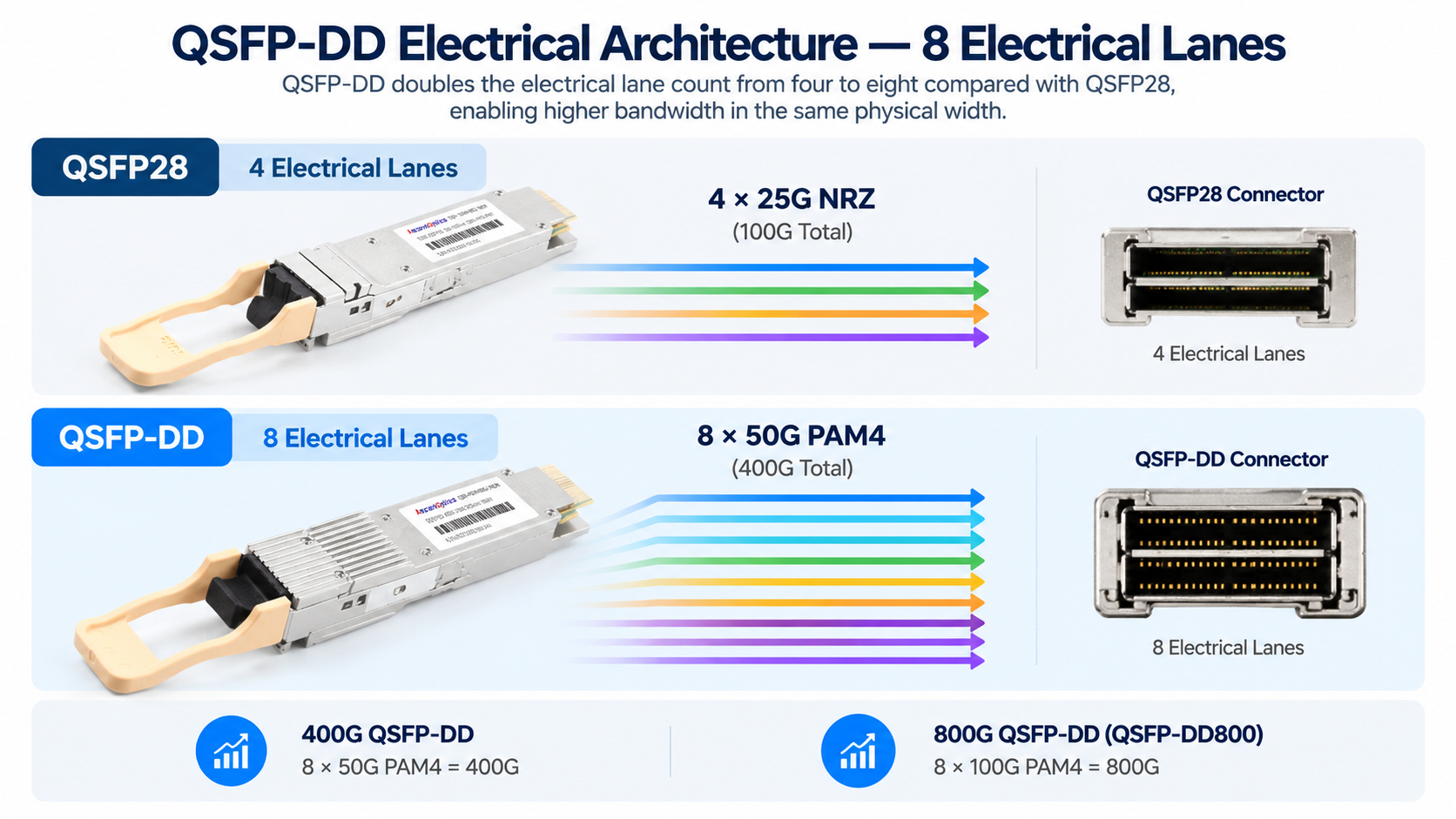
QSFP-DD stands for Quad Small Form-factor Pluggable Double Density. Compared with four-lane QSFP interfaces, its double-density connector architecture supports eight electrical lanes. A common 400GbE implementation uses eight approximately 50 Gb/s PAM4 lanes (400GBASE-CR8), while QSFP-DD800 supports eight approximately 100 Gb/s PAM4 lanes. Other 400G electrical lane arrangements also exist; the physical connector alone does not determine the Ethernet mode.
A QSFP-DD DAC cable is a direct attach copper assembly with QSFP-DD connectors on both ends. It carries electrical signals over twinax copper instead of optical fiber. That direct path is the reason it matters so much for short-reach links.
QSFP-DD Form Factor and Electrical Architecture
QSFP-DD adds a second row of electrical contacts while retaining the QSFP-family width, enabling eight-lane connections in a compact front-panel footprint. Mechanically, QSFP-DD receptacles are designed to accept earlier four-lane QSFP-family modules. Operational backward compatibility still depends on the host port, speed support, firmware, power and thermal limits, and the inserted module or cable.
The reverse is not true. A QSFP-DD module or cable cannot plug into a legacy QSFP28 port. The extra row of electrical contacts required for the eighth lane simply does not exist on the older receptacle.
How Passive DAC Works
A passive QSFP-DD DAC is a preterminated twinax copper assembly that carries high-speed electrical signals between host ports without optical conversion or an in-cable retimer. Its behavior depends on the transmitters, receivers, equalization, and FEC in the attached equipment. Avoid treating passive copper as a zero-latency link: propagation delay remains and is determined mainly by cable length.
Passive DAC cables contain no signal-conditioning ICs and generally require little or no cable-side operating power beyond identification and management circuitry. Reported power varies by assembly and measurement convention; use the vendor specification rather than a universal wattage. Their simple construction can reduce component count, but specific failure-rate claims require field reliability data.
Reach is constrained by insertion loss, impedance discontinuities, crosstalk, host equalization, and the operating lane rate. Many 400GBASE-CR8 QSFP-DD passive DAC offerings are approximately 1–3 m, while 800G passive copper offerings may have shorter published reaches. Always check the qualified part number and host platform.
QSFP-DD DAC Types and Specifications
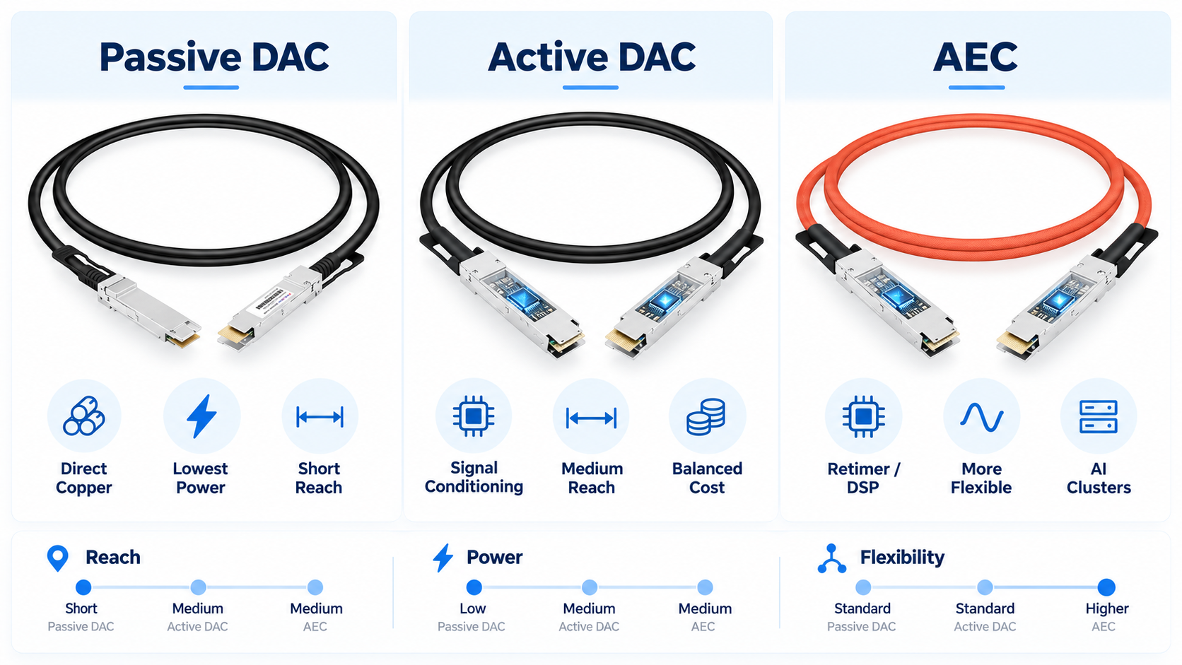
Choosing a cable starts with understanding the three families now shipping in the market. Passive DAC remains the volume leader. Active DAC and AEC extend reach where passive copper runs out of margin.
Passive QSFP-DD DAC cables contain no electronic signal conditioning. They rely on the quality of the copper conductors and the equalization built into the switch ASIC. That simplicity makes them the lowest-cost, lowest-power option for reaches up to three meters.
Active copper DAC assemblies incorporate electronic signal-conditioning circuitry, such as linear redrivers or other active components, in one or both connector ends. Redrivers provide analog gain/equalization without full clock recovery; retimers recover timing and regenerate the signal. Product categories vary among suppliers, so compare the actual component architecture, supported PHY, power draw, latency, and validated reach rather than assuming all active DAC cables perform identically.
AEC: The Middle Category
Active Electrical Cable (AEC) commonly refers to an active copper assembly using retiming or more substantial signal processing to overcome channel loss. In marketing literature, the terms active DAC, ACC, and AEC sometimes overlap. To make an engineering comparison, identify whether a product is passive, redriver-based, or retimer-based, and confirm its electrical interfaces and host qualification.
Depending on lane rate, cable construction, and signal-processing technology, active copper products can reach several meters and may offer easier routing than thick passive twinax. Neither a fixed 5–7 m reach nor a guaranteed price or power ranking applies to every 400G or 800G AEC. Consult product datasheets for qualified lengths and actual cable diameter.
Cable Gauge (AWG) Selection
Cable gauge directly affects flexibility, weight, and maximum reach. Thinner cables are easier to route in dense racks but suffer higher signal loss. Thicker cables support longer distances at the cost of stiffness.
Common passive DAC gauges include 30, 28, and 26 AWG, but availability and supported reach vary across products. A larger AWG number indicates a thinner conductor: 30 AWG is generally lighter and more flexible, whereas 26 AWG can lower conductor loss but increases stiffness and cable-bundle volume. Do not use AWG alone to approve a reach; inspect the exact 400G/800G SKU and host validation.
Breakout Configurations
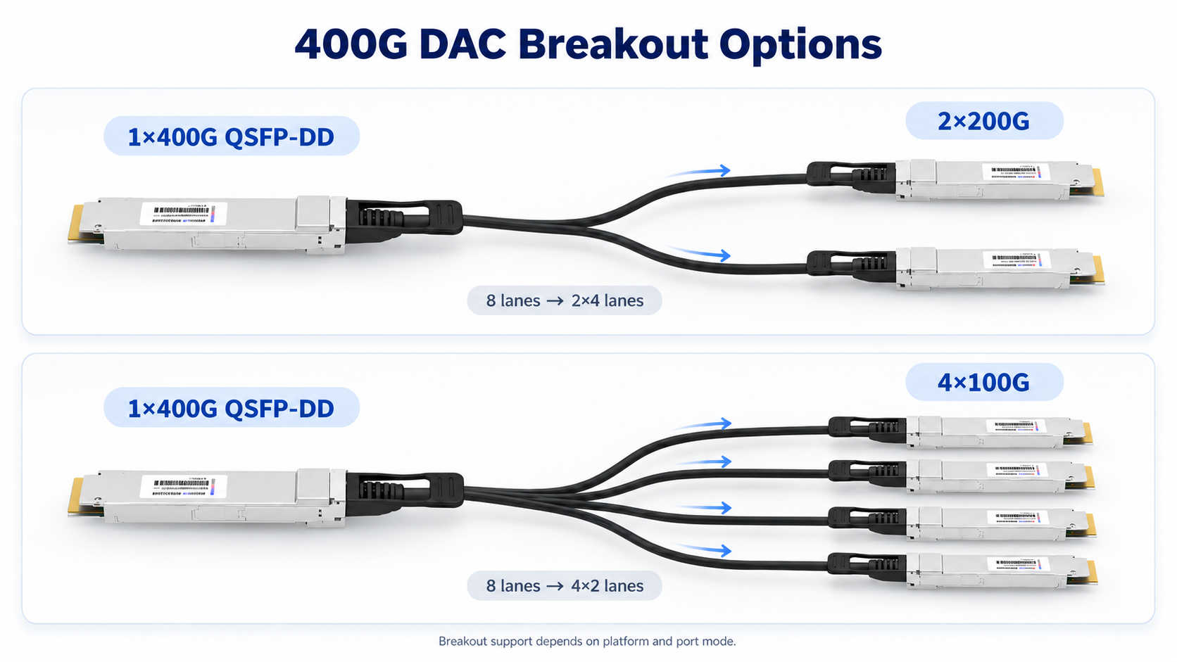
QSFP-DD breakout copper cables distribute a supported high-speed host port into several lower-speed interfaces. A typical 400GBASE-CR8 implementation uses eight 50G-class PAM4 lanes and may support 2×200GBASE-CR4, provided both endpoints and the switch breakout mode match the cable lane mapping.
Some 400GBASE-CR8 QSFP-DD platforms also support 4×100GBASE-CR2 breakout, with two approximately 50G PAM4 lanes per 100G branch. This is not equivalent to legacy 100GBASE-CR4, which uses four approximately 25G NRZ lanes. A passive breakout cable cannot convert between these PHYs. Check the exact 100G connector/cable type, lane mapping, host breakout capabilities, and supported PHY before ordering; do not assume every QSFP28 port can be connected by a 4×100G copper fanout.
QSFP-DD DAC vs AOC vs AEC vs Optical Transceivers
Distance is a useful first filter, but a comparison must also include specific PHY, power measured per end versus per cable assembly, host qualification, latency, routing, and total link cost. The figures below are indicative rather than universal product ratings.
| Interconnect |
Typical reach* |
Cable/module power |
Cost position |
Key consideration |
Best for |
| Passive QSFP-DD DAC |
Short; often 1–3 m at 400G |
Very low cable-side |
Usually lowest |
Platform and lane-rate qualified |
Intra-rack links |
| Active DAC / AEC |
Several metres; SKU-dependent |
Higher; design-dependent |
Above passive DAC |
Redriver vs. retimer varies |
Extended copper links |
| AOC |
Typically tens of metres |
Active optics at both ends |
Quote-dependent |
Fixed integrated assembly |
Lightweight inter-rack fiber |
| Optical modules + fiber |
From short reach to km-scale |
Module-dependent |
Quote-dependent |
Removable optics and patch cords |
Flexible or longer links |
*Indicative ranges only. Verify actual part-number specifications and both endpoints.
Comparison by Distance
Passive copper is typically preferred for short in-rack links, with available lengths dependent on 400G versus 800G signaling and the qualified platform. Active DAC and retimed AEC can provide longer electrical reaches when supported. 400G AOC assemblies are commonly sold in lengths up to tens of meters; their maximum reach must be checked per SKU rather than inferred from OM3/OM4 limits. Pluggable optics with separately selected fiber support much longer distances, including 400GBASE-DR4 around 500 m and 400GBASE-LR4 around 10 km where specified.
Comparison by Power and Thermal Impact
For an apples-to-apples comparison, count both ends of every interconnect and distinguish cable-side power from module and host-side electrical power. Passive DAC typically needs little cable-side power, whereas active copper and optical modules draw more. For example, 32 optical modules at 7–12 W each would consume approximately 224–384 W in module power; 32 complete links with a module at both ends require 64 modules, or approximately 448–768 W. Actual results depend on the product and whether the comparison is per port or per complete link.
This matters beyond the switch itself. Less heat reduces cooling load, lowers operational cost, and can extend the life of adjacent equipment. Operators targeting better Power Usage Effectiveness should factor this into rack-level thermal models.
Comparison by Cost and TCO
Passive DAC usually provides a low acquisition cost for short links, while active copper, AOC and discrete optics add functionality and cost. However, claims such as “one-fifth of AOC” or “one-tenth of optics” cannot be applied industry-wide. Compare current matched-speed quotations for complete links, including optics at both endpoints, fiber patch cords where applicable, approved cable lengths, and spares.
A three-year total-cost analysis should include purchase price, module or cable-side power, cooling, cabling and rack-management labor, platform qualification, expected replacements, and maintenance practices. Reliability varies by manufacturer, operating conditions, and installation quality; do not assign fixed annual failure rates to DAC or AOC without supporting population-level field data.
When to Choose Each Option
Choose passive QSFP-DD DAC when an approved short copper assembly meets the channel loss and routing requirements. Consider active copper or AEC where a validated extended reach is needed. Select AOC where fiber routing, cable weight, or electromagnetic immunity is important, and separate optical transceivers where longer reach, repair flexibility, or structured fiber infrastructure is required.
800G, QSFP-DD800, and OSFP
The jump from 400G to 800G reopens the form-factor question. This is where many teams get stuck, because the answer is no longer automatic.
QSFP-DD800 and OSFP Form Factors
QSFP-DD800 supports eight approximately 100G PAM4 electrical lanes within the QSFP-DD family. OSFP is physically larger and also supports high-speed eight-lane implementations. QSFP-DD-family receptacles offer backward mechanical compatibility with earlier QSFP variants, subject to host and firmware support. Form factors cannot be interchanged mechanically: a QSFP-DD cable does not plug into an OSFP cage.
Thermal implementation depends on both module construction and the host cage. QSFP-DD modules commonly rely on heat transfer to the system cooling solution, while OSFP products exist in different thermal variants, including versions with integrated heat sinks and flat-top modules designed for host-provided cooling. Neither form factor guarantees a higher usable power limit across every switch platform.
Why OSFP Is Gaining Ground in AI Clusters
High-density AI fabrics require careful thermal and power budgets. OSFP is used in many high-bandwidth switch and accelerator platforms, but QSFP-DD800 is also available in 800G-capable systems. Evaluate the actual switch-port architecture, airflow, system support matrix, and module or cable power rather than choosing a form factor solely because it is marketed for AI.
Which to Choose for 800G
Select QSFP-DD800 or OSFP according to the installed switch and NIC receptacles first: the connector must physically match the port. Then assess speed and breakout support, host qualification, thermal budget, cable availability, and future expansion. Many systems standardize on one type; do not assume both can be fitted in the same port.
Data Center Deployment Scenarios
QSFP-DD DAC cables earn their place in a few specific spots. Here is where they fit best.
Top-of-Rack to Server Connections
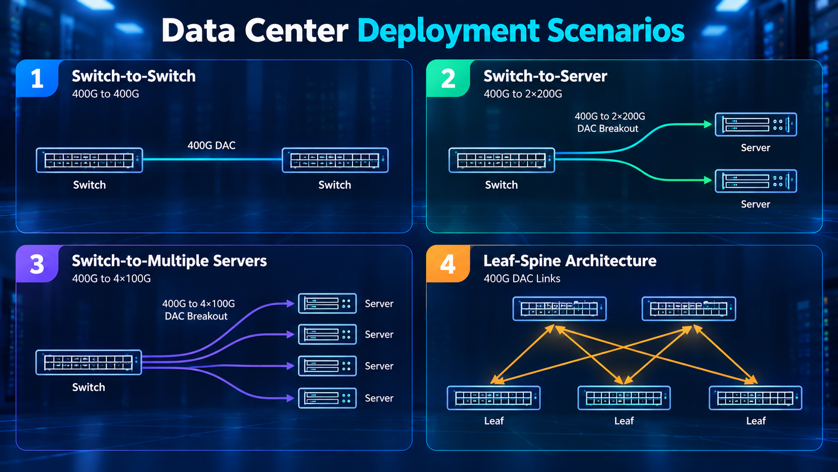
Top-of-rack switches frequently connect to nearby servers and storage systems over short DAC links. Where both devices have qualified 400G QSFP-DD ports, passive copper can simplify deployment and minimize cable-side power. Confirm NIC connector type, link speed, lane mapping, reach, and the actual rack routing path before choosing 26/28/30 AWG.
AI and GPU Cluster Interconnects
AI and GPU clusters use a mix of Ethernet and InfiniBand interconnects, as well as multiple connector families including QSFP-DD and OSFP. For short supported Ethernet links, passive DAC can be a cost- and power-efficient option. Do not assume every H100/H200-based system exposes QSFP-DD 400G/800G ports or that a named DGX/HGX reference design universally prefers QSFP-DD DAC. Verify the specific networking adapter and switch configurations.
Leaf-Spine Interconnects (Short Reach)
In spine-leaf architectures, leaf switches connect to spine switches at 400G. When leaf and spine switches sit in adjacent racks, link distances may fall within the two to three meter range of passive DAC. Many data centers, however, place spine switches at the end of a row, which pushes distances beyond three meters. In those cases, active DAC, AEC, or AOC becomes necessary. Always measure the actual cable path, not the straight-line distance between racks.
Migration from 100G/200G to 400G/800G
QSFP-DD-family ports may offer practical migration paths using qualified QSFP28/QSFP56 modules, but supported legacy speeds and breakout modes are platform-specific. A 400G QSFP-DD port can serve multiple lower-speed interfaces only when the host supports the required breakout PHY and the branch endpoints match the signaling format. In particular, 4×100GBASE-CR2 breakout must not be confused with legacy 100GBASE-CR4.
Compatibility and Standards Compliance
A cable that meets the physical spec still has to pass the vendor’s compatibility check. This is where deployments commonly stall.
QSFP-DD MSA and IEEE Standards
The QSFP-DD MSA defines the form-factor, connector, cage, and related mechanical/electrical requirements; management requirements are covered by applicable CMIS revisions. For Ethernet PHY references, 400GBASE-CR8 was introduced in IEEE 802.3bs. IEEE 802.3ck addresses 100 Gb/s-per-lane electrical interfaces and related copper PHYs, while IEEE 802.3df-2024 adds 800GbE parameters and PHYs, including 800GBASE-CR8. Select the precise standard for the advertised product rather than treating form-factor compliance as equivalent to Ethernet PHY compliance.
The Common Management Interface Specification (CMIS) defines management interfaces for relevant pluggable modules and cable assemblies. Supported CMIS revision and readable diagnostics depend on the cable and host implementation. In particular, passive DAC assemblies may expose identification data without active temperature telemetry. Confirm exact management capabilities in the supplier datasheet and host documentation.
Switch and NIC Compatibility
QSFP-DD and QSFP-DD800 support varies across vendor switch and NIC families. Do not assume every Cisco, Arista, Juniper, or NVIDIA platform uses QSFP-DD; some high-bandwidth systems use OSFP or other cages. Even a mechanically fitting assembly may be rejected due to platform coding, speed, FEC, electrical implementation, or software restrictions. Verify the exact switch/NIC model and approved cable SKU.
FEC Requirements and Signal Integrity
FEC configuration must match the Ethernet PHY and platform implementation. Many high-speed PAM4 Ethernet links use Reed–Solomon FEC, but the applicable code and configuration are determined by the specific 400G/800G mode, not the QSFP-DD connector alone. A passive cable does not negotiate FEC on its own; host ports, link training, and management software govern link establishment as specified by the applicable PHY. Follow the switch and NIC vendor guidance and confirm the required FEC mode at both ends.
Signal integrity testing should address insertion loss, return loss, mode conversion, crosstalk, lane mapping, and appropriate compliance or interoperability tests. BER acceptance criteria differ by measurement location and whether FEC is enabled; a generic post-FEC BER target must not be presented as an intrinsic passive cable specification. For volume deployments, request applicable compliance results and validate representative cables on production hardware.
Installation Best Practices
Getting the cable choice right is half the job. Installing it correctly is the other half.
Pre-Deployment Verification
Verify switch firmware compatibility before cables arrive. Some early 400G switch releases required firmware updates to support QSFP-DD passive DAC operation. Check release notes for your platform and software version. If you use breakout cables, confirm the switch port supports breakout mode and that you configured the correct lane mapping.
For critical deployments, request sample cables for pre-production testing. Measure BER, confirm CMIS readability, and test insertion and extraction force. A cable that is too tight or too loose in the cage can cause intermittent contacts during thermal cycling.
Physical Routing Guidelines
Follow the cable manufacturer’s specified minimum static and dynamic bend radii, including any larger minimum near the connector strain relief. These limits vary with AWG, overall cable diameter, and construction; fixed values such as 25–35 mm cannot safely apply to every assembly. Avoid sharp folds, crushing, and tensile loading of the plug.
Route DAC cables separately from power cables to minimize electromagnetic interference. In high-density racks with dozens of 400G links, poor cable management creates crosstalk and blocks airflow. Use horizontal and vertical cable managers to keep bundles organized. Label both ends of every cable before installation.
Post-Installation Validation
After installation, confirm the expected link speed, negotiated or configured PHY mode, breakout mapping, operational FEC, and error counters. Run an appropriate traffic and BER test where equipment supports it; built-in PRBS facilities are model-dependent. Record relevant corrected and uncorrected FEC counters, not just link-up status.
Monitor the host-reported diagnostics that are actually supported by the attached product. Passive DAC may not report a cable temperature, whereas active copper and optical assemblies can expose additional diagnostics. Check for increased errors after thermal stabilization and high-load operation, and retain baseline measurements for troubleshooting.
Conclusion
QSFP-DD DAC assemblies provide economical electrical interconnects for short 400GbE and qualified 800GbE deployments. Passive options minimize in-cable electronics; active copper and retimed AEC can extend reach for compatible platforms. Successful selection depends on lane rate, PHY and FEC compatibility, validated cable length, connector type, and realistic thermal and routing constraints.
The selection criteria are straightforward. Before you order, run through this checklist:
- Measure the actual cable path, not the straight-line distance between racks.
- Choose AWG and maximum length from a qualified product datasheet rather than applying a universal 30/28/26 AWG distance chart.
- Validate the switch/NIC model, supported Ethernet PHY, breakout mode, firmware, and required FEC settings at both endpoints.
- For 800G, match QSFP-DD800 or OSFP to the physical host port, then confirm power, cooling, and speed/breakout requirements.
Every interconnect decision affects power budgets, cooling loads, and deployment timelines. Getting these details right prevents costly rework and keeps infrastructure projects on schedule.
Frequently Asked Questions (FAQ)
1. What is a QSFP-DD DAC cable?
A QSFP-DD DAC (Direct Attach Copper) cable is a high-speed copper interconnect used for short-distance connections between switches, servers, and storage devices. It supports 400G or 800G Ethernet depending on the cable type and host interface.
2. What is the difference between QSFP-DD DAC and QSFP56 DAC?
QSFP-DD uses eight electrical lanes, while QSFP56 uses four. A 400G QSFP-DD DAC typically uses 8×50G PAM4 signaling, whereas a 200G QSFP56 DAC uses 4×50G PAM4. Both are designed for high-speed, short-reach connections.
3. Can QSFP-DD DAC cables support both 400G and 800G?
QSFP-DD supports 400G, while QSFP-DD800 extends the architecture to 800G using eight 100G-class electrical lanes. A 400G QSFP-DD DAC cable should not be assumed to support 800G. The cable assembly and both host ports must support the required speed.
4. What is the maximum length of a 400G QSFP-DD DAC cable?
Passive 400G QSFP-DD DAC cables commonly support distances of up to approximately 3 meters. Active copper solutions may extend the reach, depending on the cable design, signal conditioning technology, and host capabilities.
5. Can a 400G QSFP-DD DAC cable break out into 4×100G?
Yes, certain 400G QSFP-DD ports support breakout into 4×100G links using compatible cable assemblies. However, the electrical lane configuration and signaling must match the supported breakout mode. Not every 100G QSFP28 device supports the required interface.
6. What is the difference between passive DAC, active DAC, and AEC?
Passive DAC carries electrical signals without active conditioning components. Active DAC includes signal-conditioning electronics, while AEC (Active Electrical Cable) generally uses retiming or more advanced signal processing to improve signal integrity. Reach, power consumption, and cost vary by implementation.
7. Is QSFP-DD DAC compatible with Cisco, Arista, and NVIDIA switches?
QSFP-DD DAC cables can be compatible with supported Cisco, Arista, and NVIDIA platforms. Compatibility depends on the switch model, port type, firmware, supported speeds, and cable identification requirements. Always verify compatibility before deployment.
8. Does a QSFP-DD DAC cable require FEC?
FEC requirements depend on the Ethernet PHY, signaling mode, and host implementation. Many 400G and 800G Ethernet copper interfaces use Reed-Solomon FEC. Both endpoints must support compatible FEC operation for reliable link establishment.
Post Views: 118