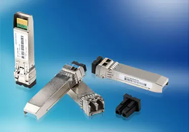
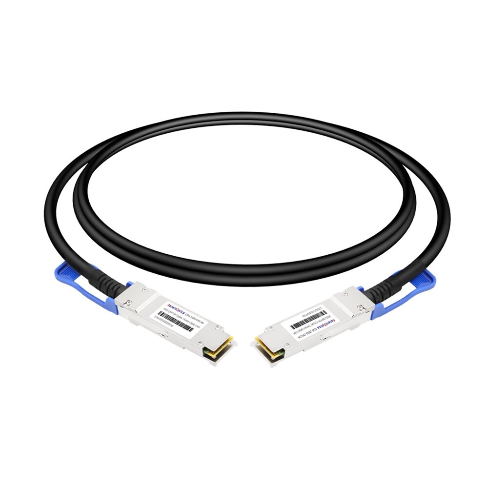
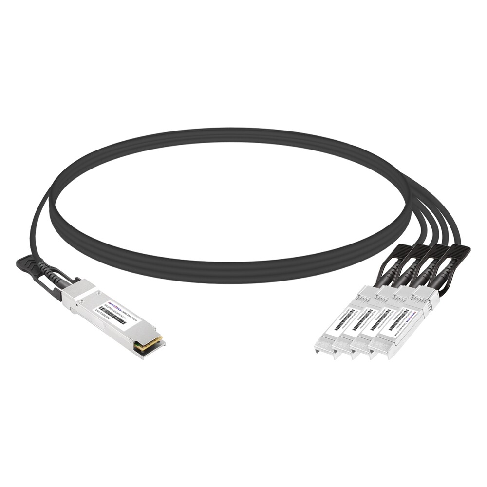
For short, high-bandwidth links within or between adjacent racks, 200G QSFP56 direct attach copper (DAC) cables can deliver a practical combination of low power consumption, low latency and attractive cost. However, the right cable depends on the Ethernet or InfiniBand protocol, port configuration, cable length, and actual platform qualification—not connector appearance alone.
What Is a 200G QSFP56 DAC Cable?
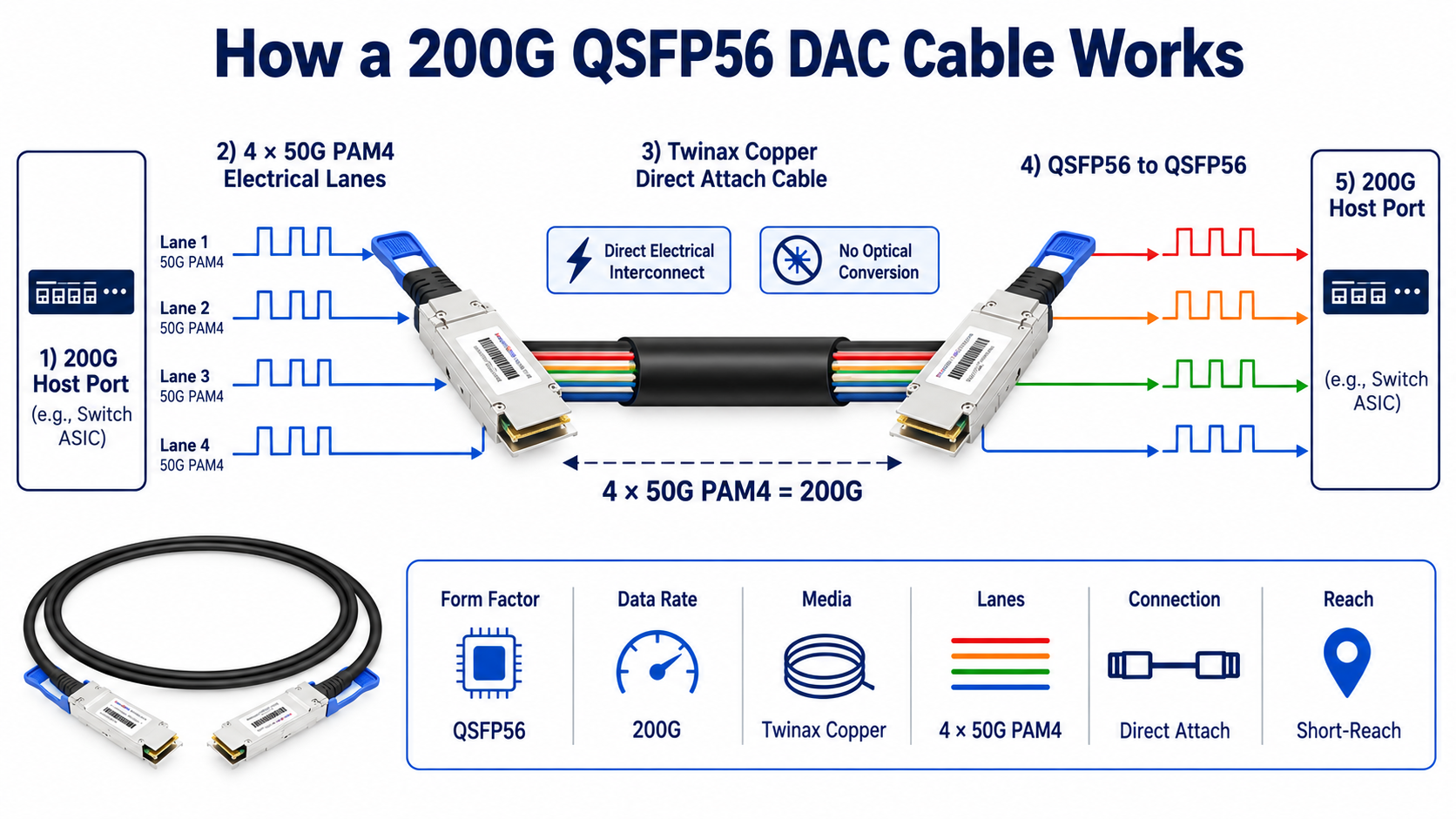
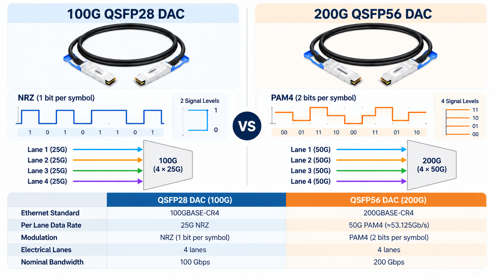
A 200G QSFP56 DAC is a factory-terminated twinax copper cable assembly with QSFP56 plugs at its ends. In a typical 200GbE 200GBASE-CR4 application, it carries four electrical lanes using 50G-class PAM4 signaling (approximately 53.125 Gb/s per lane, before accounting for coding/FEC overhead). The nominal four-lane Ethernet MAC rate is 200 Gb/s.
Unlike optical transceivers, passive DACs do not require optical emitters, receivers or separate fiber jumpers. Each plug usually includes a memory device that reports identification and cable characteristics to the host. Many QSFP56 cable assemblies use SFF-8636-compatible management; CMIS 4.0 is not a universal prerequisite for QSFP56 DAC operation. Features and telemetry depend on the specific product.
IEEE 802.3cd defines the 200GBASE-CR4 copper PHY. QSFP mechanical, electrical and management requirements should be checked against the cable supplier’s applicable MSA/SFF documentation and the host vendor’s interoperability requirements.
QSFP56 vs. QSFP28: What Changes at 200G?
| Characteristic |
Typical 100G QSFP28 DAC |
Typical 200G QSFP56 DAC |
| Electrical data lanes |
4 × 25G-class NRZ |
4 × 50G-class PAM4 |
| Nominal Ethernet rate |
100GbE |
200GbE |
| Copper link example |
100GBASE-SR4 |
200GBASE-SR4 |
| Interchangeability |
Depends on port capabilities |
200G requires PAM4-capable host ports |
NRZ encodes one bit per symbol; PAM4 carries two bits per symbol, allowing a higher bit rate without doubling the symbol rate. PAM4 imposes stricter signal-integrity requirements. IEEE 200GBASE-CR4 uses RS(544,514) FEC, and the host must support the required PHY and FEC settings.
The QSFP28 and QSFP56 families have related mechanical form factors, but a 100G QSFP28 cable is not automatically qualified for a 200G PAM4 link. Conversely, some QSFP56-capable host ports can run supported 100G NRZ configurations. This is host- and cable-specific; do not assume either direction of compatibility.
Passive DAC vs. Active Copper Cable (ACC)
Passive 200G QSFP56 DAC
Passive DACs contain no active signal-conditioning circuitry in the transmission path. They generally offer the lowest cable-assembly power consumption and cost. Practical reach is limited by insertion loss, return loss, crosstalk, wire gauge, connector design and the host receiver equalization budget.
For planning, passive 200G copper is commonly used over short runs of approximately 0.5–3 m, but this is not a universal standard-defined purchasing limit. For example, some manufacturers qualify their 200GbE passive cables to 2 m while offering 3 m for InfiniBand. Always rely on the exact cable SKU and deployment qualification.
Active Copper Cable (ACC)
An ACC integrates active electrical components such as equalization or redriver circuitry to improve high-speed signal performance over longer copper assemblies. Supported lengths and power draw depend on the architecture and part number. Several commercial 200G ACC families reach around 3–5 m; longer offerings should be individually verified rather than treating 7 m as a guaranteed limit.
| Option |
Typical deployment |
Power / reach notes |
| Passive DAC |
Shortest same-rack links |
Near-zero active electronics power; short validated reach |
| ACC |
Longer copper links |
Additional power at plugs; SKU-specific supported length |
| AOC |
Longer, flexible rack-to-rack links |
Optical conversion consumes power; product-specific reach |
| Optics + fiber |
Flexible topology / longer distances |
Separate transceivers and fiber; depends on optic type |
Length, Gauge, and Signal Integrity
Reach isn’t just a passive-versus-active question. Wire gauge and signal integrity determine whether a given copper length will actually work.
AWG and Maximum Reach
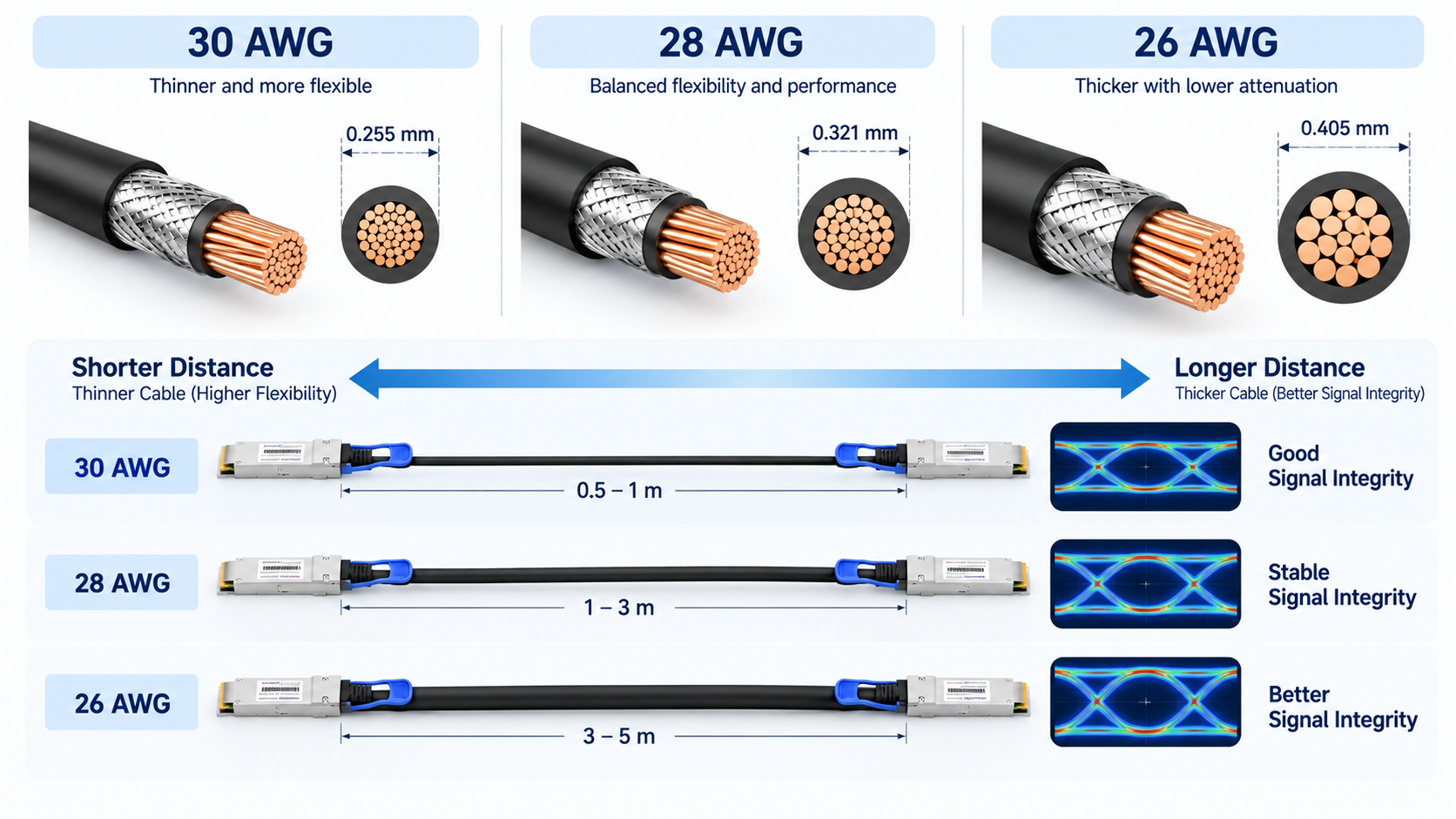
Thicker wire carries 50G PAM4 signals farther. That’s why QSFP56 DAC cables step up in gauge as they get longer. Vendors typically use 30 AWG for short cables up to about 1.5 meters, 28 AWG for 2 meters, and 26 AWG for 2.5 to 3 meters.
Thicker gauge improves signal integrity but makes the cable stiffer and heavier. In a dense rack, that stiffness matters. A 3-meter 26 AWG cable is noticeably harder to route cleanly than a 1-meter 30 AWG cable.
Insertion Loss and the 3-Meter Passive Limit
The 3-meter ceiling on passive QSFP56 DACs comes down to insertion loss and crosstalk. PAM4 has a tighter signal-to-noise budget than NRZ, so the copper run has less margin to absorb loss. Beyond about 3 meters, the signal degrades past what the host can correct, even with FEC.
That’s the hard boundary to respect. If your cable run even approaches 3 meters, measure it carefully and confirm with the vendor before committing.
Airflow and EMI Considerations
Copper DACs are also thicker than fiber, which means they block more airflow in high-density racks. In a fully populated 32-port QSFP56 leaf switch, dozens of copper cables can measurably restrict cooling. And because DACs carry electrical signals, they’re susceptible to electromagnetic interference, unlike fiber.
For most same-rack deployments, these are minor issues. But in dense, noisy environments, they’re worth factoring into the design.
Compatibility: Verify the Exact Host and Port
A switch family’s advertised 200GbE capability does not automatically mean it has a native QSFP56 receptacle. Some platforms provide 200G over native QSFP56 ports, while others reach 200G through OSFP/QSFP-DD breakout configurations. Physical plug type, breakout cable construction and software support must all match.
| Platform example |
How to interpret support |
| NVIDIA Spectrum-2 SN3700 |
Documented 32 × native QSFP56 200GbE ports; supports supported 2 × 100G and 4 × 50G breakout modes. |
| NVIDIA SN4600 |
QSFP56-capable variants offer native 200G ports; check exact model/port mapping and breakout restrictions. |
| Arista 7060X4 / 7060X6 |
High-speed QSFP-DD or OSFP-family host ports; 200G support does not imply a native QSFP56 socket. |
| Other Cisco / Arista / Juniper platforms |
Use exact model, line card, OS release, port type and qualified cable list; avoid series-wide claims. |
A third-party cable may require approved identification coding at each end, particularly for mixed-vendor links. Dual-coded cable assemblies can be useful, but coding alone does not guarantee interoperability: verify the PHY mode, host equalization/FEC, vendor acceptance and actual link testing.
200G QSFP56 Breakout Options
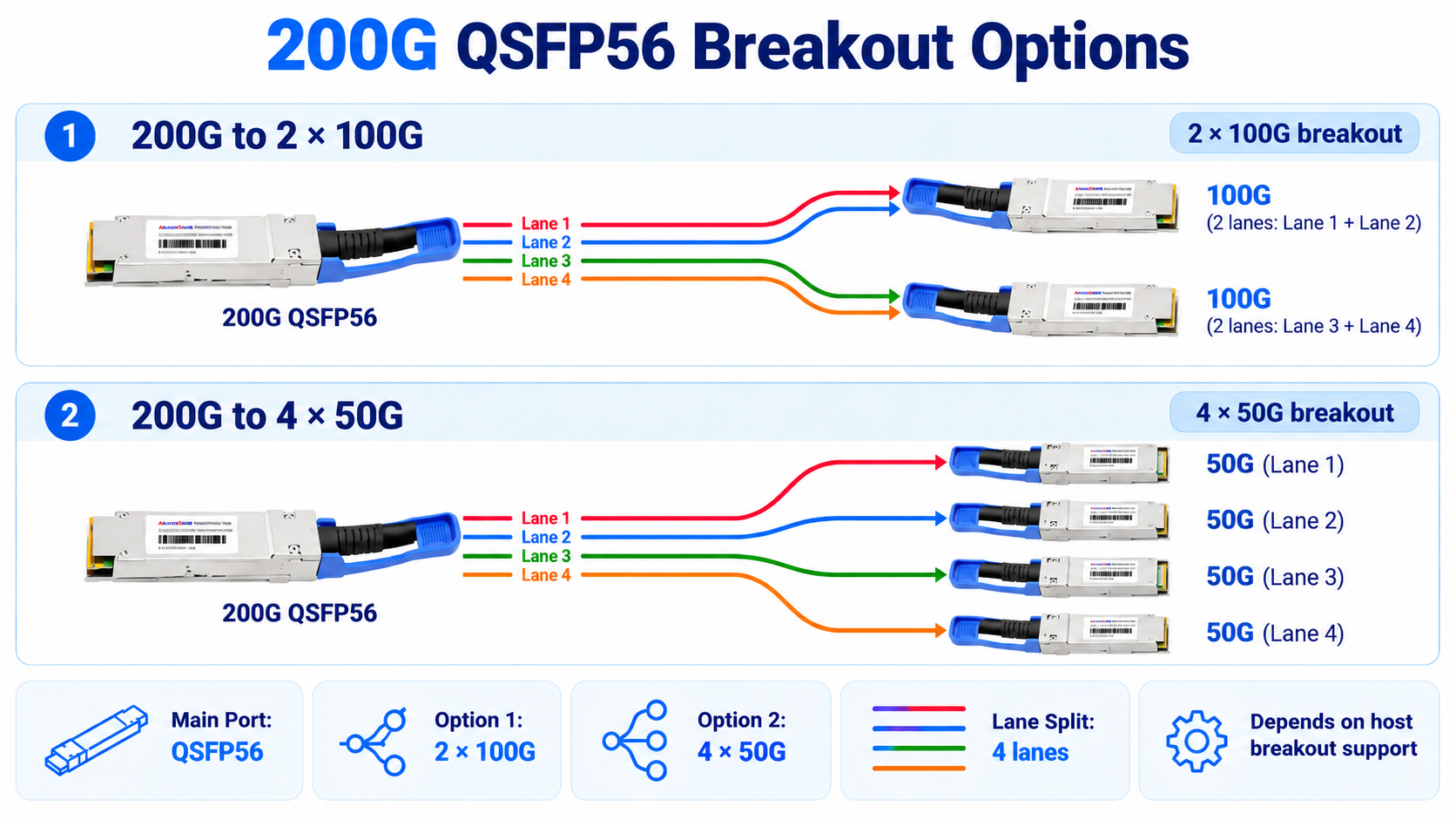
200G to 2 × 100G
A qualified 200G QSFP56 to 2 × 100G breakout cable divides the four high-speed lanes into two two-lane 100G PAM4 connections, typically using QSFP56 connectors at the branches. Each endpoint must support that 100G electrical lane configuration; it is not equivalent to every legacy four-lane 100G QSFP28 host.
200G to 4 × 50G
A 200G QSFP56 to 4 × 50G SFP56 breakout can allocate one 50G PAM4 lane to each branch. The switch must expose a compatible four-way breakout mode and the four server/NIC ports must support the appropriate 50G signaling and FEC.
Before selecting a breakout, confirm exact port-map restrictions, software version, lane polarity and electrical mode. Adjacent ports may be disabled in some breakout configurations.
How to Choose the Right 200G QSFP56 DAC
Work through these six criteria in order, and you’ll land on the right cable quickly.
- 1. Measure the distance first. Under 3 meters points to a passive DAC. Three to 7 meters points to active DAC or AOC. Over 7 meters means AOC or optical transceivers.
- 2. Pick the type. Passive for the shortest, cheapest, lowest-latency links. Active when you need a few more meters and still want copper.
- 3. Match the gauge to the length. Shorter runs use 30 AWG; longer runs step up to 28 AWG or 26 AWG for signal integrity.
- 4. Confirm compatibility on both ends. Verify switch model, NIC model, target speed, and software version before ordering.
- 5. Decide on breakout. Use 2×100G or 4×50G breakouts only when you need to fan a single port out to slower endpoints.
- 6. Factor in airflow and density. In tightly packed racks, account for cable stiffness and airflow blockage.
QSFP56 DAC vs. AOC: Which Makes Sense?
Within a short, validated copper reach, passive DAC often minimizes incremental power consumption and purchase cost. AOC becomes attractive when the route needs more flexibility, lower cable bulk, electrical isolation or a longer reach. Avoid comparing total switch power using generic fixed per-port figures: passive DAC, ACC and AOC products have widely varying power specifications. For a meaningful comparison, multiply the actual manufacturer-specified power per assembly or endpoint by the deployed port count.
Frequently Asked Questions
Can I plug a 200G QSFP56 DAC into a 100G QSFP28 switch?
Do not assume it will work. The electrical mode, module/cable recognition, firmware and port capability must be validated. A legacy 100G-only QSFP28 port does not become 200G-capable by using a QSFP56 cable.
Is FEC required for 200GBASE-CR4?
Yes. RS(544,514) FEC is part of the 200GBASE-CR4 Ethernet PHY requirements. Ensure the host configuration matches the applicable implementation and link mode.
Can every 200G QSFP56 port break out to 4 × 50G?
No. Breakout is a feature of the host silicon, port group and operating software, not simply a feature of the cable.
What is the maximum distance of a passive 200G QSFP56 DAC?
There is no single supplier-independent answer. Many offerings target roughly 2–3 m or less; the exact certified reach varies with protocol, cable construction and endpoint qualification.
Conclusion
200G QSFP56 DAC cables are a compelling choice for short-reach, high-density data center connections when the hardware and link budget are qualified together. Select by interface and signaling first, then by supported length, FEC, breakout, and platform coding. Treat vendor data sheets and interoperability tests—not generic length tables—as the final authority.
Post Views: 80