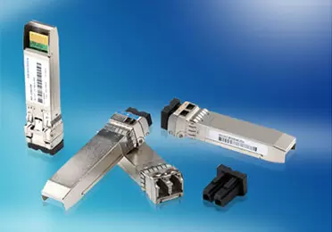
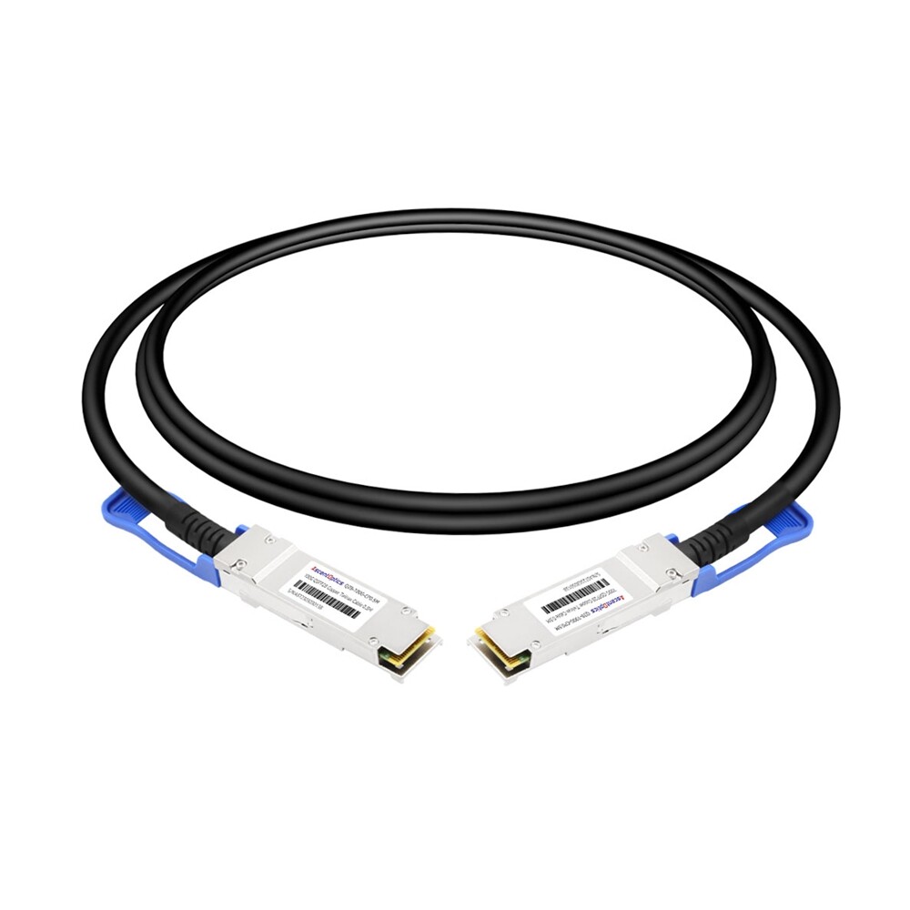
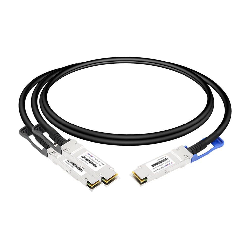
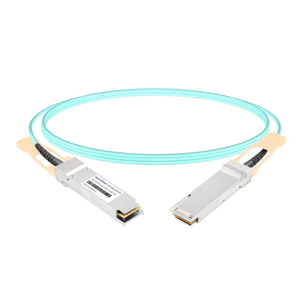
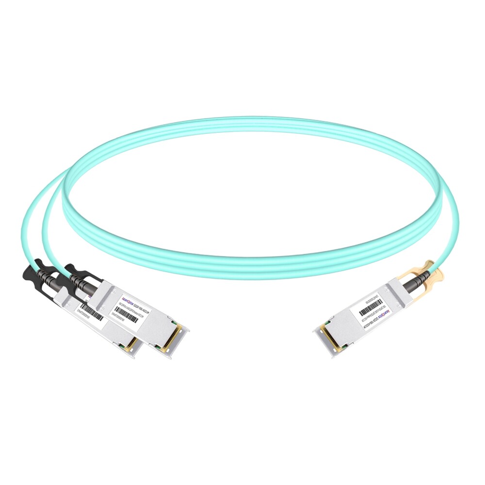
100G QSFP28 DAC (Direct Attach Copper) cables are passive, high-speed interconnects that eliminate the need for optical-to-electrical conversion modules. Offering low power consumption, low cost, and minimal latency, they are widely used for short-range, rack-to-rack interconnections within data centers, making them a cost-effective choice for 100G high-speed networking.
What Is a QSFP28 DAC Cable?
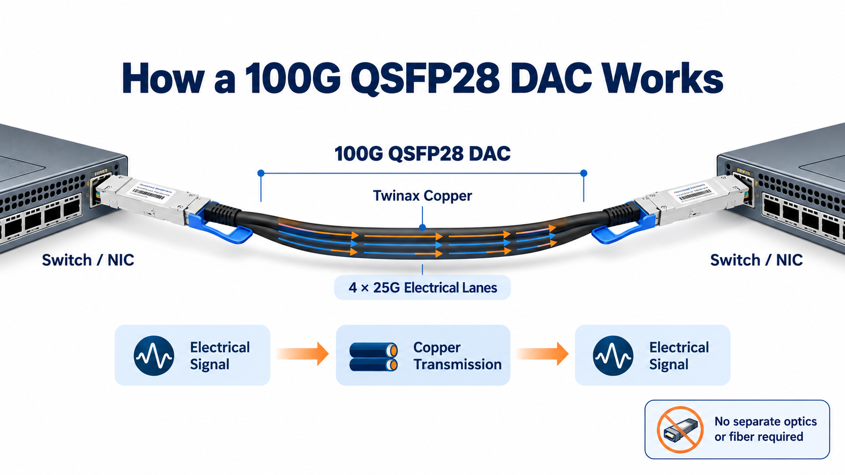
A QSFP28 DAC cable is a twinax copper assembly with QSFP28 connectors permanently attached at both ends. It carries 100 Gbps over four 25 Gbps electrical lanes, with no separate transceivers or fiber required.
Unlike an optical module setup, a DAC has no pluggable optics to install and no patch cord to clean. The connectors are built in, the copper is fixed, and the whole assembly is factory-terminated. You plug it in, and the link comes up.
The “DAC” stands for Direct Attach Copper, and the “QSFP28” refers to the connector form factor. Each connector carries an EEPROM that identifies the cable to the host switch or NIC, reporting things like vendor, length, and supported FEC mode.
This design matters because it removes several failure points at once. There is no optical-to-electrical conversion, no connector mating between transceiver and fiber, and no laser to age or fail. For short reach, copper is simply the more reliable medium.
Passive vs Active QSFP28 DAC: What’s the Difference?
QSFP28 DAC cables come in two flavors, and the difference is whether any electronics sit in the signal path.
Passive DAC
A passive DAC is a straight length of twinax copper with no active components at all. It draws essentially zero power, typically under 0.1 W per end, and adds no latency beyond the physical speed of the signal through the wire.
Passive DACs are the default choice for the vast majority of data center links. They are cheap, reliable, and effectively unbreakable in normal operation. Their only real limitation is reach, which is set by signal attenuation in the copper.
Active DAC (ACC)
An active DAC, sometimes called an active copper cable (ACC), adds a small driver or equalizer chip inside each connector. That chip conditions the signal so it can travel farther, pushing reach from around five meters out to seven or more.
The tradeoff is a little power and a little money. An active DAC draws roughly 0.5 to 2.5 W per end, still well below an optical transceiver. You reach for an active DAC only when a passive one won’t span the distance and you want to stay on copper.
In practice, most 100G top-of-rack deployments never need active copper. Passive covers the rack, and if a run is genuinely longer, an AOC or optics becomes the cleaner answer anyway.
QSFP28 DAC Maximum Length and Distance
Reach is the first thing to check on any DAC, because it is the one hard limit you cannot work around.
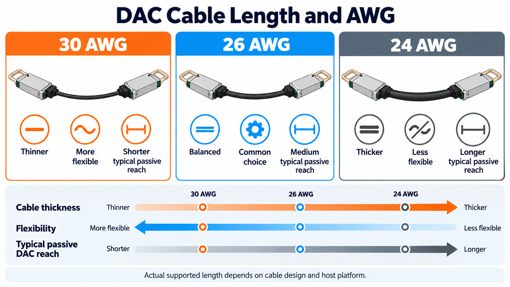
A passive QSFP28 DAC typically tops out between one and five meters, with some vendors listing up to seven. Wire gauge is what drives that ceiling:
- 30 AWG thin cable: 1 to 2 meters
- 26 AWG mid cable: 2 to 5 meters
- 24 AWG thick cable: up to 5 meters
Thicker wire carries a signal farther, but it is also stiffer and harder to route. That is the fundamental tension in DAC selection: reach versus manageability.
The practical rule is simple. If the server and switch are in the same rack or an adjacent one, a passive QSFP28 DAC almost certainly fits. Past roughly seven meters, you move to an active optical cable or a discrete transceiver with fiber.
Power, Latency, and FEC: The Engineering Tradeoffs
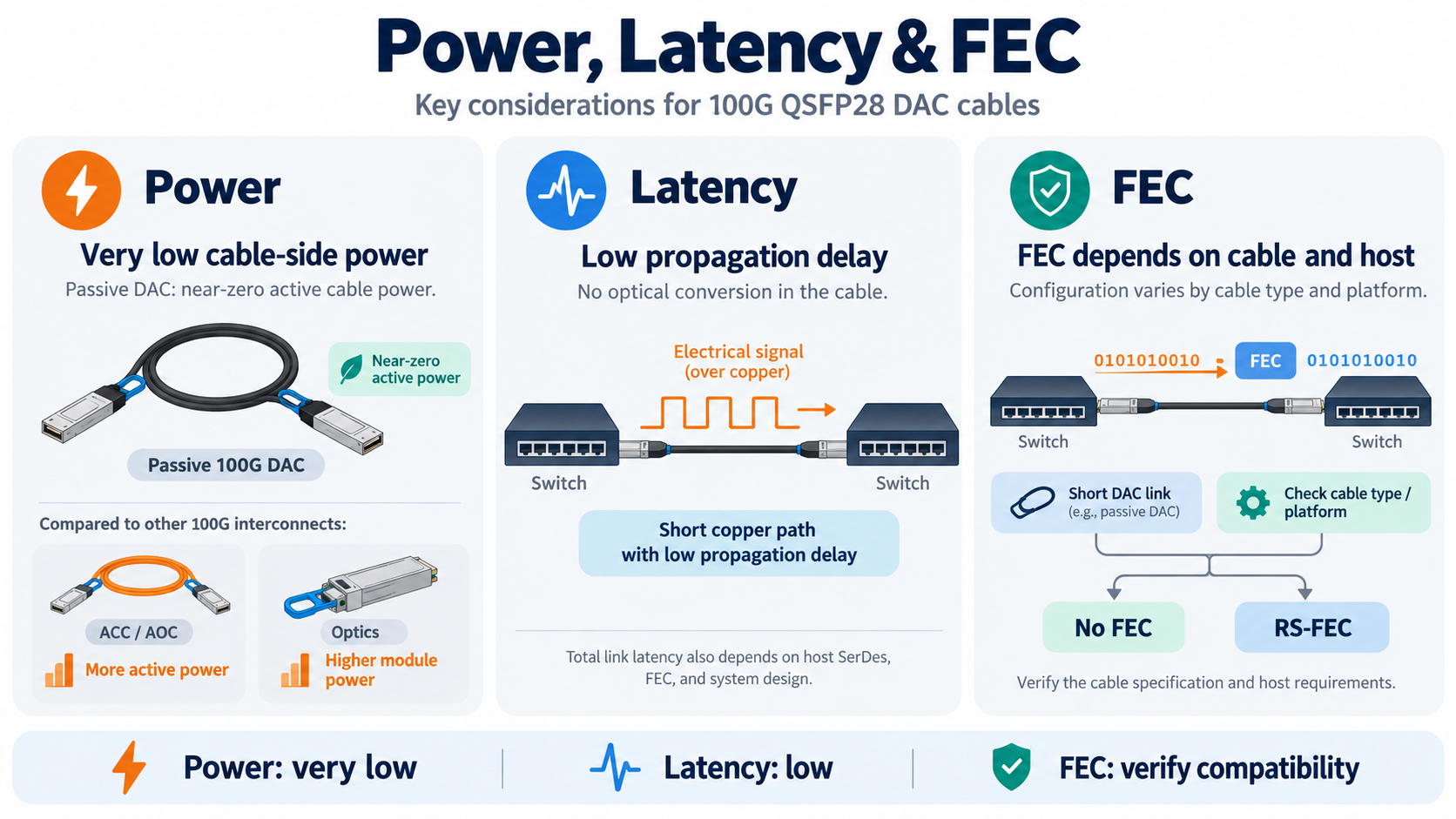
DACs win on three engineering fronts that matter more than raw throughput: power, latency, and FEC overhead.
Power consumption
A passive QSFP28 DAC is the lowest-power 100G interconnect you can buy. It draws less than 0.5 W and often near zero, because there is nothing to power.
An optical transceiver is a different story. A 100GBASE-SR4 module pulls roughly 3.5 W per end. That difference scales dramatically: Siemon’s high-speed interconnect research found that saving one watt at the server translates to about 2.5 W saved across the data center, once you account for cooling and power-delivery overhead.
Latency
DACs also carry the lowest latency of any interconnect type. Because there is no optical-to-electrical conversion, a passive DAC adds only the propagation delay of the signal through copper, on the order of 0.1 to 0.3 microseconds.
That margin sounds small, but it is decisive for high-frequency trading, HPC fabrics, and tightly coupled GPU clusters, where every microsecond of serialization and conversion overhead compounds across thousands of nodes.
FEC: the setting most people get wrong
Forward error correction (FEC) is where short DAC links get an extra advantage, and where long ones can trip you up.
NVIDIA’s LinkX documentation and Dell’s 100G DAC listings describe the same rule. Cables up to two meters can run with no FEC (CA-25G-N), which saves both latency and power. Cables from three to five meters generally require RS-FEC (CA-25G-L) to keep the signal clean.
If your switch tries to run a three-meter DAC with FEC disabled, the link may flap or fail to come up at all. The fix is a one-line FEC-mode change, but it is a common source of “compatible” cables that mysteriously don’t work.
QSFP28 DAC Switch Compatibility and Vendor Coding
A QSFP28 DAC is physically compatible across switch vendors, as long as it follows the QSFP28 MSA and SFF-8665 electrical specs. The catch is that many switches check the connector’s EEPROM before they bring the link up.
That EEPROM stores a vendor code. Cisco, Arista, Juniper, NVIDIA (Mellanox), Dell, and Huawei all ship switches that may reject a cable whose code they don’t recognize. This is a software policy, not a hardware limitation.
Third-party “compatible” DACs work by presenting the EEPROM signature the switch expects, while costing a fraction of the OEM part. The engineering is identical; the difference is the label and the price.
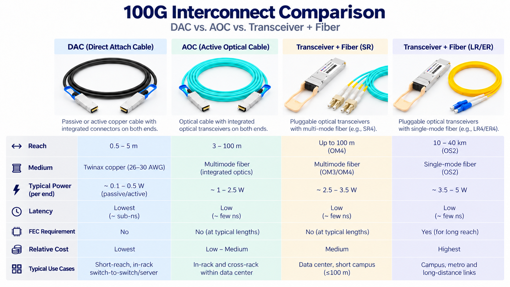
The three 100G interconnect options are complementary, not competing. The distance between devices should drive the decision.
| Feature |
QSFP28 DAC |
AOC |
Optical Transceiver |
| Medium |
Copper twinax |
Integrated fiber |
Separate module + patch cord |
| Max reach |
~5 m passive, 7–15 m active |
100 m or more |
70 m to 120 km |
| Power (100G) |
Under 0.5 W passive |
1–2 W per end |
~3.5 W+ per end |
| Latency |
Lowest |
Low |
Higher |
| Cost |
Lowest |
Low to mid |
Highest |
| Best use |
ToR, under 5 m |
10–50 m inter-rack |
Over 100 m, flexible/WDM |
Here is the decision framework in plain terms:
- Under 5 meters: passive DAC, almost always. Lowest cost, lowest power, lowest latency.
- 5 to 50 meters: AOC or active copper. Fiber-like reach and EMI immunity without managing separate transceivers.
- Over 100 meters: discrete optical transceivers. Nothing else gets you there.
One more cost note worth internalizing. A single optical transceiver end costs roughly two to three times the total cost of a point-to-point DAC or AOC assembly. When you multiply that by two ends and thousands of ports, the copper-versus-optics decision is one of the largest line items in a data center budget.
How to Choose a QSFP28 DAC Cable
Choosing the right DAC is mostly about removing ambiguity before the order goes in. Run through these seven checks in order.
- 1. Confirm both end devices. Note the exact switch or NIC model, software version, and whether the 100G port is in a specific mode.
- 2. Measure the actual route. Account for cable management and slack. Common lengths are 0.5, 1, 2, 3, and 5 meters.
- 3. Pick passive first. If the run is under five meters, a passive DAC is almost always the right answer.
- 4. Check the FEC mode. Under two meters, no FEC; three meters and up generally needs RS-FEC enabled.
- 5. Verify vendor compatibility. Confirm the cable’s EEPROM coding matches your switch platform.
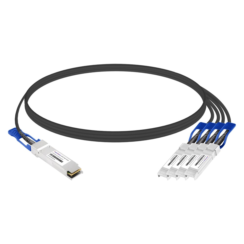
- 6. Consider a breakout. A QSFP28-to-4×SFP28 breakout DAC turns one 100G port into four 25G links, a cheap way to fan out to servers.
- 7. Buy from a manufacturer, not just a reseller. You want engineering support and a compatibility list, not a box with no one behind it.
Breakout DACs: stretch a 100G port further
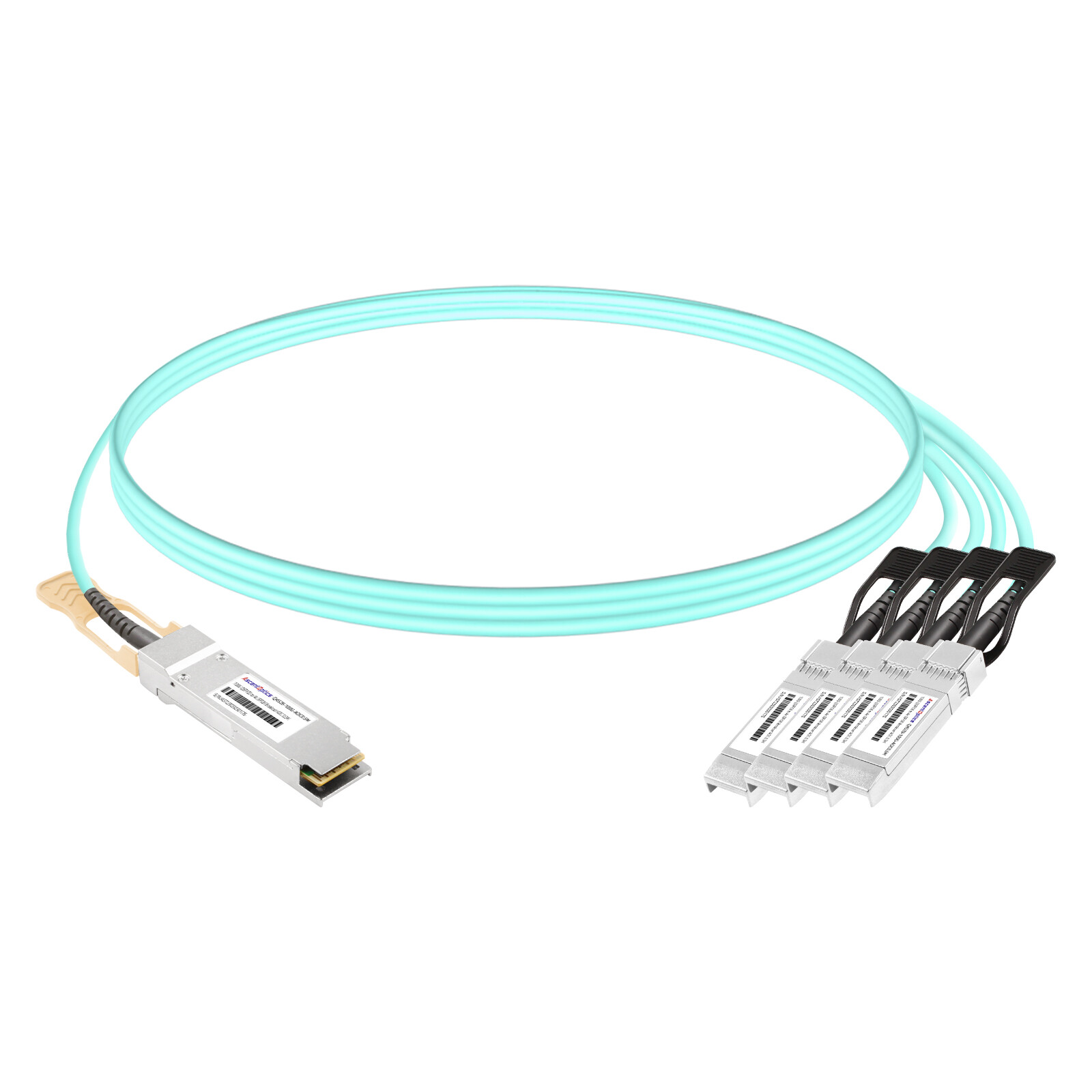
A QSFP28 to 4×SFP28 breakout cable connects a single 100G switch port to four 25G servers or NICs. It is one of the cheapest ways to add server density without buying more switch ports.
Conclusion
A QSFP28 DAC cable is the unsung hero of 100G networking. It is the cheapest, coolest, and lowest-latency way to move 100 gigabits across the short distances that make up most of a data center’s cabling.
To recap the decisions that matter:
- Under five meters, a passive QSFP28 DAC beats optics on cost, power, and latency.
- Wire gauge sets reach: 30 AWG for short runs, 26 AWG for longer, and 24 AWG when you need the full five meters.
- FEC is the hidden trap: two meters or less runs no FEC, while three meters and up usually needs RS-FEC enabled.
- Compatibility is a software question: confirm EEPROM vendor coding against your switch before ordering.
- Breakout DACs stretch a single 100G port into four 25G links, a fast path to server density.
The next step is to measure your actual cable runs and confirm your switch models. Once you have those two numbers, the right QSFP28 DAC almost picks itself.
Frequently Asked Questions (FAQ)
What is a 100G QSFP28 DAC cable?
A 100G QSFP28 direct attach copper (DAC) cable is a factory-terminated twinax assembly with QSFP28 connectors at both ends. It carries a 100G link using four nominal 25 Gb/s electrical lanes, without separate optical transceivers or fiber patch cords.
How far can a passive 100G QSFP28 DAC cable reach?
Passive 100G QSFP28 DACs are commonly offered in lengths of roughly 0.5–5 m. Supported reach varies with cable construction, wire gauge, electrical channel quality, and host equipment; verify the exact SKU and platform qualification rather than assuming a universal maximum.
Does a 100G DAC cable require FEC?
Not always. FEC depends on the electrical channel class, cable model, host port implementation, and supported link settings—not distance alone. Some validated short assemblies support FEC-disabled operation, while other assemblies require a specific FEC mode. Confirm settings at both ends and check error counters.
What is the difference between passive DAC and active copper cable (ACC)?
Passive DAC contains no active cable-side signal-conditioning electronics. ACC uses active circuitry, such as equalization or re-driving, to improve electrical signal integrity in supported designs. ACC typically consumes more cable-side power; its reach and compatibility are model-specific.
Does passive QSFP28 DAC consume power?
A passive DAC has essentially no active signal-processing power draw in the cable assembly. Host ports still consume power, and any identification/management circuitry may draw a small amount. Compare system-level and module-level power on a consistent basis.
Is DAC always lower latency than optical fiber?
No universal end-to-end latency ranking applies. A passive DAC avoids cable-side active processing and its propagation delay is only a few nanoseconds per meter, but the complete link also includes SerDes, FEC, and switch/NIC processing.
Can a QSFP28 DAC cable connect switches from different vendors?
Potentially, if both ends support the required 100G mode, cable type, FEC configuration, and identification requirements. Physical QSFP28 fit alone does not guarantee link-up. Check the compatibility matrix for both devices and their software versions.
Can one 100G QSFP28 port connect to four 25G ports?
Yes, when the 100G port explicitly supports 4 × 25G breakout. A QSFP28-to-4×SFP28 breakout DAC can connect to four compatible 25G ports; both sides must have matching speed, FEC, and platform settings.
When should I choose AOC or optical transceivers instead of DAC?
Consider AOC when a fixed integrated optical assembly better meets reach, cable weight, or routing needs. Choose separate optical transceivers and fiber for structured cabling, patch panels, independently replaceable parts, or longer-distance links. Verify the exact optics and fiber specification.
Post Views: 39