The same QSFP cage that carries your 100G traffic today can theoretically carry 400G tomorrow. The catch? The module inside must speak a completely different electrical language. That is the central tension network engineers face when comparing QSFP112 vs QSFP28. Both optical transceiver modules share identical physical dimensions, but the leap from 100G to 400G is not a simple swap. It demands new switch ASICs, different modulation schemes, and a clear-eyed assessment of what infrastructure you can keep and what must change.
What Is QSFP28? The 100G Standard
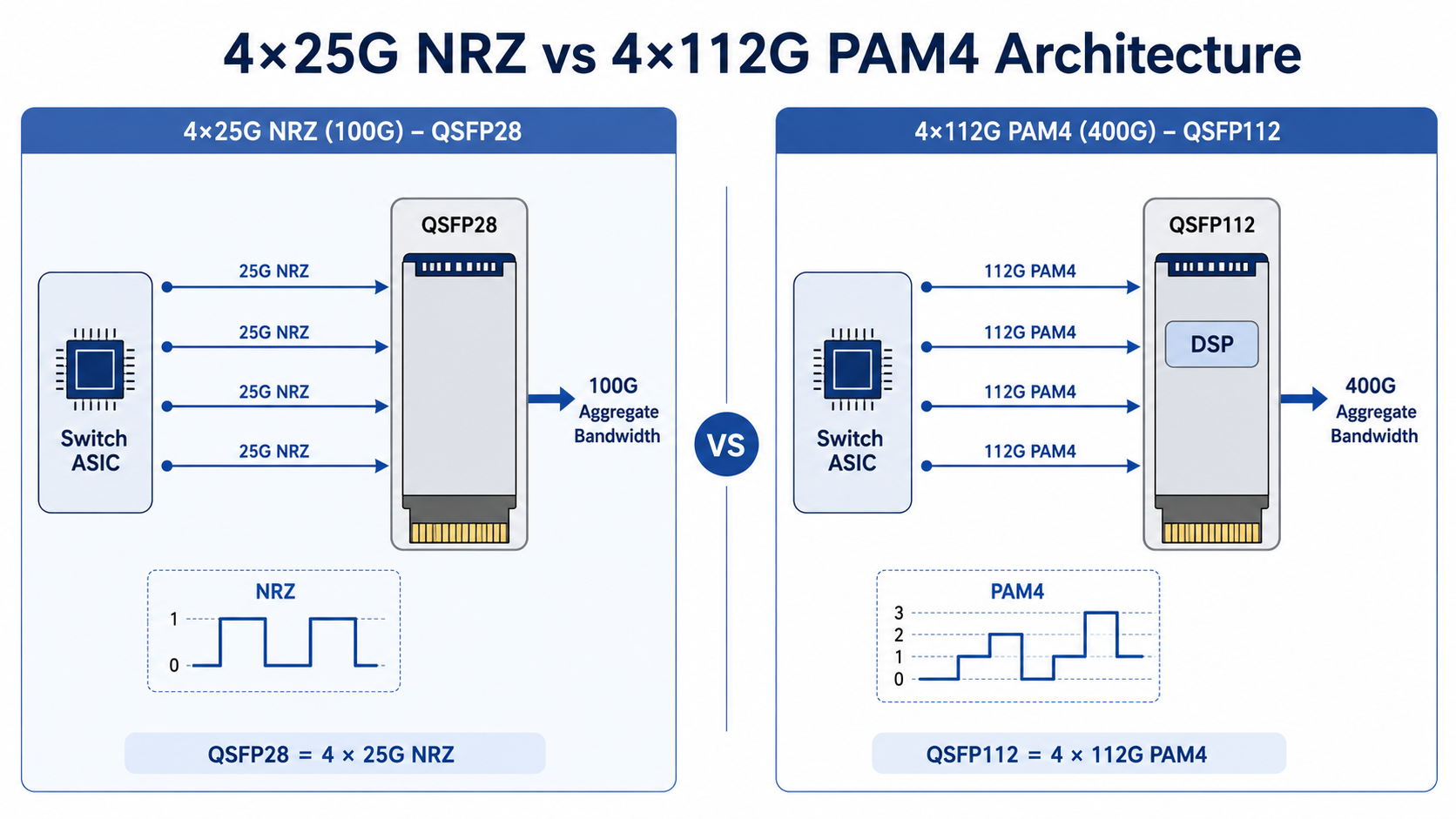
Technical Foundation: 4 x 25G NRZ
QSFP28 (Quad Small Form-factor Pluggable 28) has been the dominant 100G optical transceiver module since its widespread adoption around 2016. It achieves 100G data transmission through four electrical lanes, each operating at 25 Gbps using NRZ (Non-Return-to-Zero) modulation. This straightforward lane architecture makes QSFP28 reliable, thermally efficient, and broadly compatible across networking equipment vendors.
Common QSFP28 Module Types
Network engineers choose QSFP28 variants based on transmission distance and fiber type:
| Module Type |
Fiber |
Reach |
Use Case |
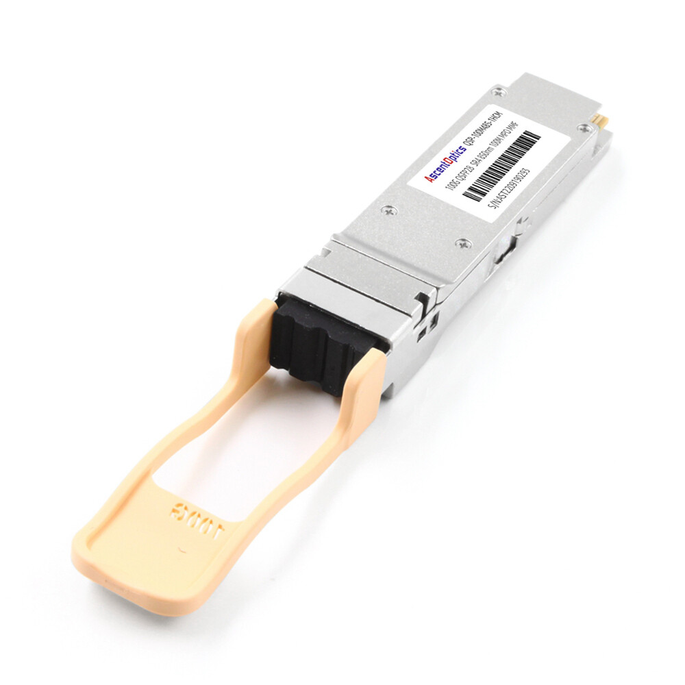
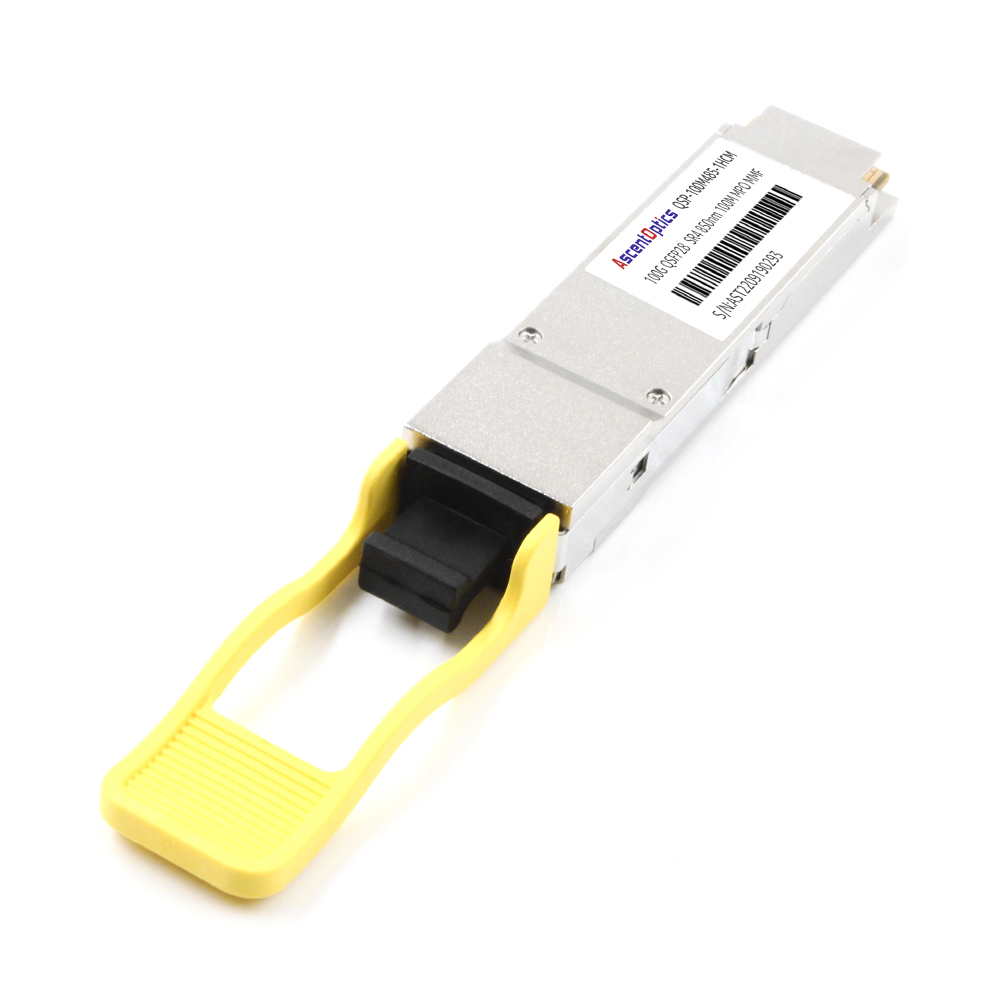
| 100GBASE-SR4 |
MMF (OM4) |
Up to 100 m |
Intra-rack and adjacent-rack links |
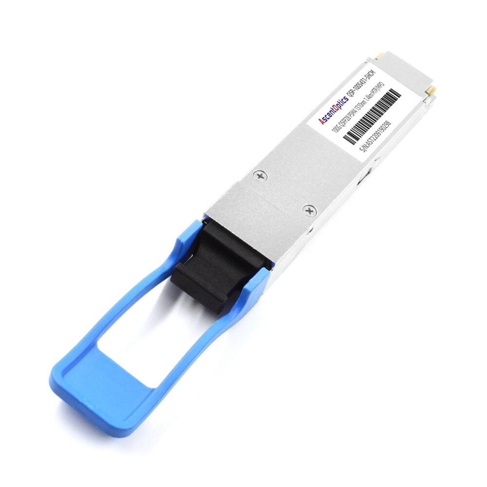
| 100GBASE-LR4 |
SMF |
Up to 10 km |
Data center interconnect, metro links |
| 100GBASE-ER4 |
SMF |
Up to 40 km |
Long-haul telecom and carrier networks |
| 100GBASE-PSM4 |
SMF |
Up to 2 km |
Spine-leaf architectures, DCI |
| 100GBASE-CWDM4 |
SMF |
Up to 2 km |
Cost-optimized data center links |
Why QSFP28 Remains Relevant
QSFP28 modules typically draw 3.5 to 6 watts per unit, making them thermally manageable in standard enterprise racks. The ecosystem is mature, with broad vendor support from Cisco, Arista, Juniper, and dozens of white-box manufacturers. For networks where 100G bandwidth is sufficient, QSFP28 continues to deliver stable performance at a cost-per-port that 400G modules have not yet matched.
What Is QSFP112? The 400G Evolution
Technical Foundation: 4 x 112G PAM4
QSFP112 is the 400G optical transceiver module that pushes the traditional 4-lane QSFP form factor to its architectural limit. Instead of scaling lane count, QSFP112 scales per-lane speed: four electrical lanes operating at approximately 112 Gbps using PAM4 (Pulse Amplitude Modulation 4-level) modulation. This delivers an aggregate 400G data transmission rate within the same physical envelope as QSFP28.
How QSFP112 Achieves 400G in the Same Form Factor
The key engineering decision behind QSFP112 was to preserve backward mechanical compatibility while maximizing bandwidth density. PAM4 modulation packs two bits per symbol, effectively doubling the data rate at the same baud rate compared to NRZ. However, PAM4 is far more sensitive to signal loss, noise, and PCB trace quality. QSFP112 modules, therefore, incorporate sophisticated Digital Signal Processing (DSP) chips to equalize and recover signals at 112G per lane.
Common QSFP112 Module Types
| Module Type |
Fiber
|
Reach |
Use Case
|
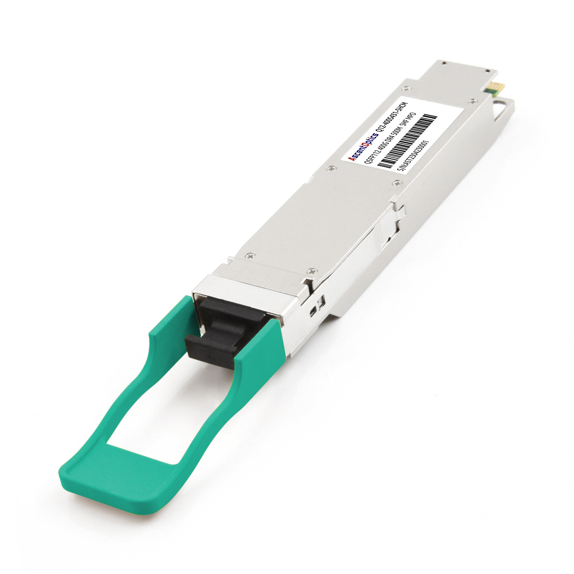
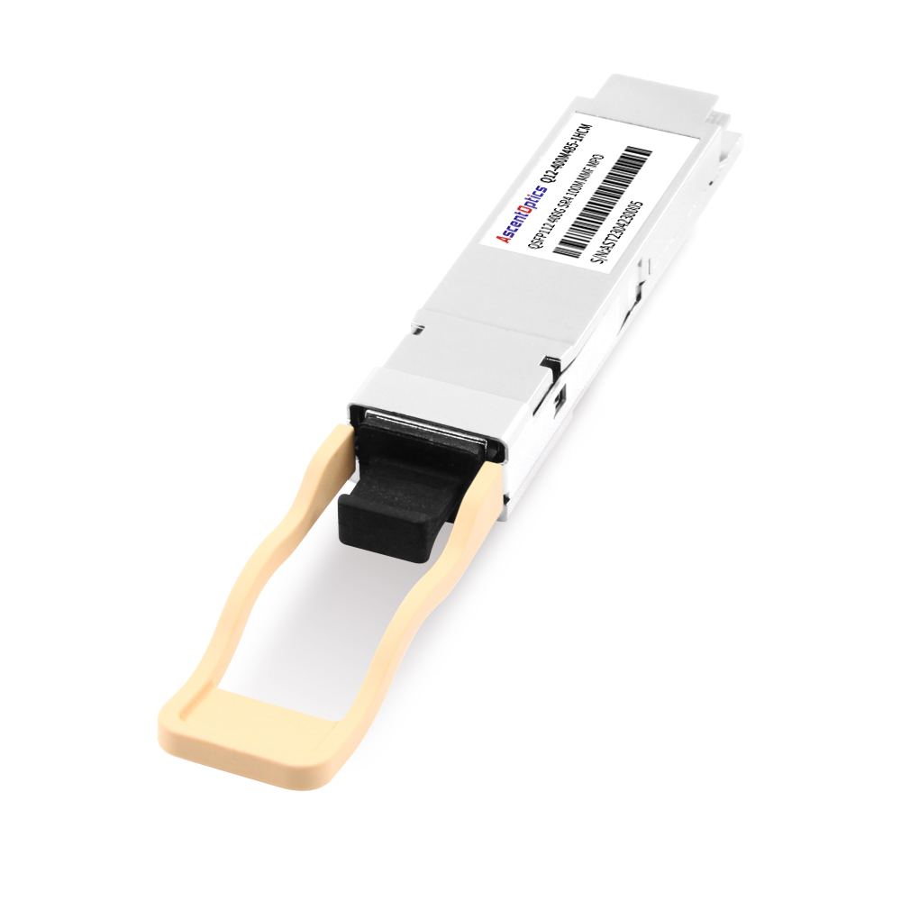
| 400GBASE-SR4 |
MMF (OM4)
|
Up to 100 m |
Intra-rack 400G links
|
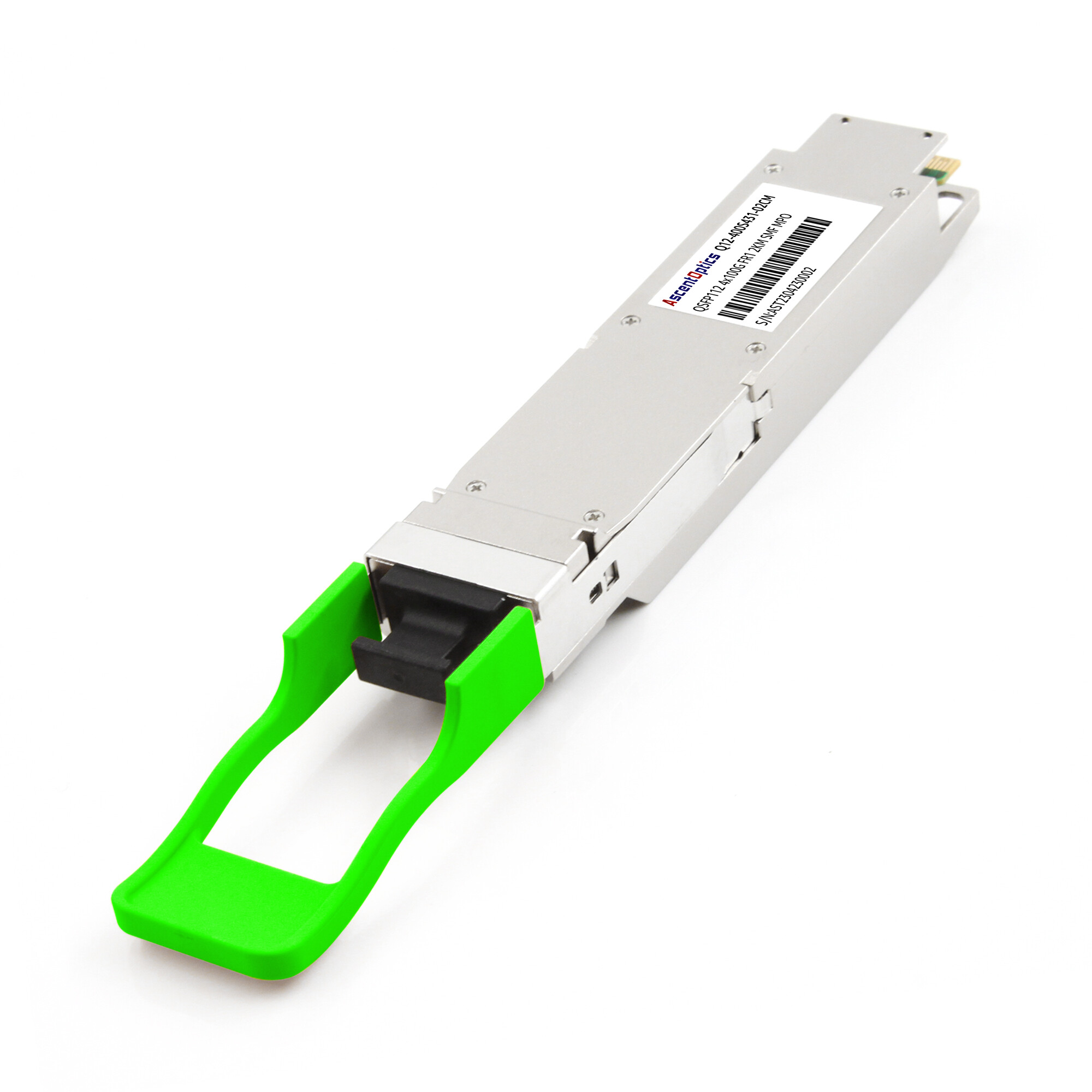
| 400GBASE-DR4 |
SMF
|
500 m |
Leaf-spine data center fabrics
|
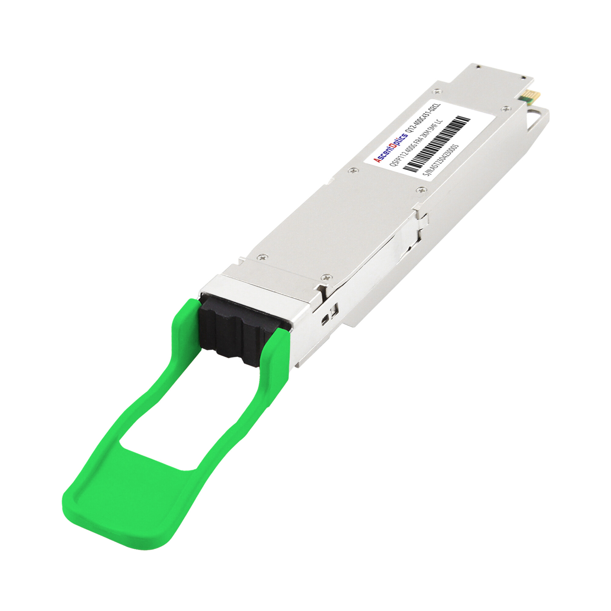
| 400GBASE-FR4 |
SMF (duplex LC)
|
2 km |
Campus, aggregation, short DCI
|
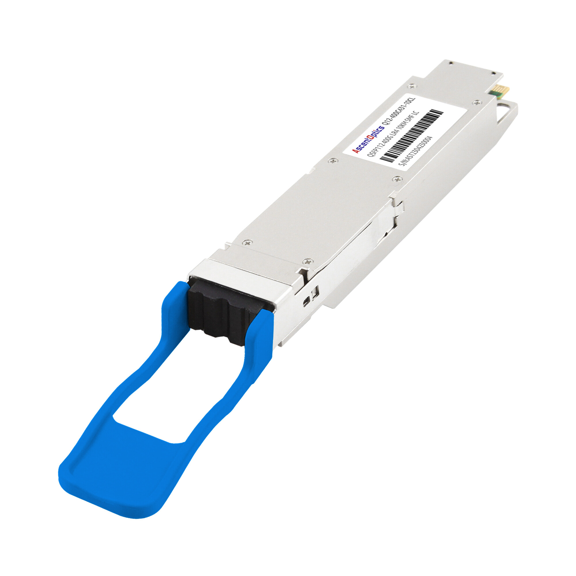
| 400GBASE-LR4 |
SMF (duplex LC)
|
10 km |
Metro and backbone links
|
QSFP112 vs QSFP28: Head-to-Head Technical Comparison
Understanding the differences between QSFP112 and QSFP28 requires looking beyond the form factor label. Here is how they stack up across the dimensions that matter for network design.
| Specification |
QSFP28 |
QSFP112 |
| Aggregate Data Rate |
100 Gbps |
400 Gbps |
| Electrical Lanes |
4 lanes |
4 lanes |
| Per-Lane Speed |
25 Gbps |
~112 Gbps |
| Modulation |
NRZ |
PAM4 |
| Form Factor Dimensions |
18.4 x 89.4 x 8.5 mm |
18.4 x 89.4 x 8.5 mm |
| Typical Power Consumption |
3.5-6W |
8-15W |
| Signal Processing |
Minimal DSP |
Advanced DSP required |
| Host ASIC Requirement |
25G NRZ SerDes |
112G PAM4 SerDes |
| Primary Use Case |
Enterprise 100G, mainstream DC |
400G upgrades, AI/HPC clusters |
| Ecosystem Maturity |
Mature (2016+) |
Emerging (2021+) |
Data Rate and Lane Architecture
QSFP28 achieves 100G with four lanes at 25 Gbps each. QSFP112 quadruples that to 400G by pushing each lane to approximately 112 Gbps. The lane count stays the same, but the signal integrity challenges increase exponentially. Every connector, trace, and via in the host PCB must handle 112G PAM4 signaling, which is significantly more demanding than 25G NRZ.
Modulation: NRZ vs PAM4
NRZ transmits one bit per symbol: a high voltage represents 1, a low voltage represents 0. It is simple, power-efficient, and tolerant of moderate signal degradation. PAM4 transmits two bits per symbol using four distinct voltage levels. This doubles throughput at the same baud rate but requires more complex receivers, tighter channel budgets, and higher power DSP. For network engineers, this means QSFP112 demands cleaner signal paths and better thermal management than QSFP28.
Power Consumption and Thermal Design
Here is where the upgrade math gets real. A QSFP28 module typically draws 3.5 to 6 watts. A QSFP112 module draws 8 to 15 watts depending on type and reach. At the switch level, a 32-port device fully populated with QSFP112 modules can consume 256 to 480 watts in optics alone, versus 112 to 192 watts with QSFP28.
When Marcus Chen, a senior infrastructure engineer at a mid-size cloud provider, planned his first 400G spine layer, he assumed his existing thermal design would scale linearly. It did not. The jump from roughly 6W to 12W per module meant his standard 15 kW racks could handle fewer switches than planned. He ended up redistributing the spine layer across two additional racks, which affected his cabling topology and power distribution units.
Backward Compatibility: The Reality
Many QSFP112-based platforms support QSFP56 and QSFP28 modules for lower-speed operation. However, backward compatibility depends on the switch ASIC, firmware, and vendor implementation, so compatibility should always be verified before deployment. This is a significant advantage for phased upgrades.
However, the reverse is not true. A legacy QSFP28 port supports only 25G NRZ signaling. You cannot plug a QSFP112 module into a QSFP28 port and expect it to function at 400G. The physical dimensions match, but the electrical interface does not. This is the single most common source of confusion during procurement.
When to Use QSFP28 vs QSFP112
Choose QSFP28 If…
- •Your network requires 100G bandwidth and has no near-term need for 400G
- •You are operating legacy switches that lack 112G PAM4 SerDes support
- •Cost per port is a primary constraint
- •Thermal headroom in your racks is already tight
- •You need maximum vendor interoperability across multiple switch brands
Choose QSFP112 If…
- •You are building or upgrading to a 400G spine-leaf architecture
- •You are deploying AI or HPC clusters where bandwidth density is critical
- •Your switch platforms support 112G PAM4 (NVIDIA Spectrum-4, Broadcom Tomahawk 4/5, Marvell TERALYNX)
- •You want to maximize port density in a power-constrained environment
- •You need 4 x 100G breakout capability from 400G ports during transition
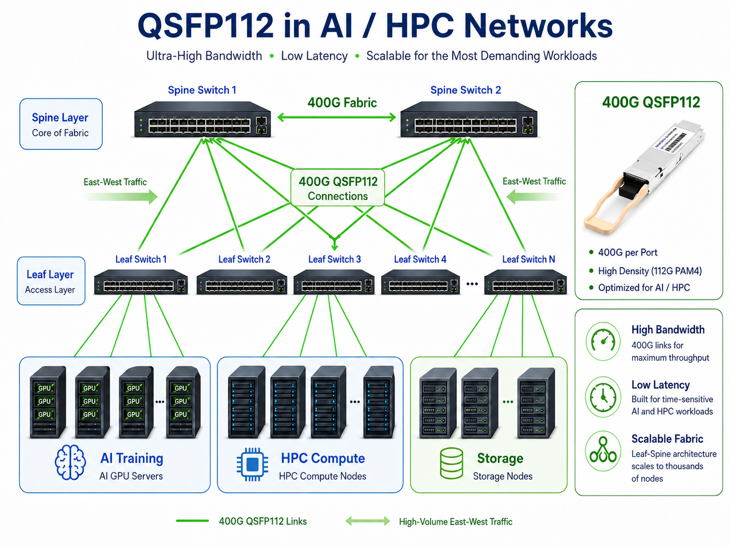
QSFP112 in AI and HPC Networks
While QSFP28 remains widely deployed in traditional enterprise and cloud networks, QSFP112 is increasingly becoming the preferred interface for AI and high-performance computing (HPC) environments.
Modern AI clusters built around NVIDIA H100, H200, and Blackwell GPUs require massive east-west traffic bandwidth between servers, storage systems, and accelerator nodes. With support for 400G Ethernet and NDR InfiniBand connectivity, QSFP112 enables significantly higher bandwidth density while maintaining the compact QSFP form factor.
Leading platforms such as NVIDIA Spectrum-4 switches, Quantum-2 InfiniBand switches, ConnectX-7 adapters, and BlueField-3 DPUs all leverage 112G PAM4 technology to deliver high-performance networking for large-scale AI training and inference workloads.
As AI infrastructure continues evolving toward 800G networking, QSFP112 is expected to remain a critical building block for interoperable 400G deployments and migration strategies.
The Transition Period: Mixed-Speed Networks
Most enterprises will not flip from 100G to 400G overnight. The realistic scenario is a mixed environment where new spine switches run QSFP112 at 400G while leaf switches and servers remain on QSFP28 at 100G. QSFP112’s breakout capability, splitting one 400G port into four independent 100G lanes, makes this transition practical rather than painful.
Migration Path: Upgrading from QSFP28 to QSFP112
Infrastructure Reuse: What Stays and What Changes
The good news is that physical infrastructure largely survives the transition. QSFP112 modules fit into the same cages, use the same latching mechanisms, and connect to the same fiber patch panels as QSFP28. Racks, cable trays, and fiber runs typically require no changes.
What must change:
- •Switch ASICs: The host switch must support 112G PAM4 SerDes. This generally means a new generation of hardware.
- •DAC and AOC cables: 100G DACs and AOCs will not carry 400G signals. New cabling rated for 400G is required.
- •Thermal management: Higher per-module power means reassessing rack cooling and power distribution.
What can stay:
- •Fiber patch panels and structured cabling: SMF and MMF fiber itself does not change for comparable reach types.
- •QSFP cages and faceplates: The mechanical form factor is identical.
- •Management and monitoring frameworks: CMIS 4.0 and later support QSFP112 digital diagnostics.
Switch and NIC Requirements for QSFP112
Before ordering QSFP112 modules, verify that your switches and network interface cards explicitly list QSFP112 or 400G support with 112G PAM4 SerDes. Major platforms supporting QSFP112 include:
- •NVIDIA Spectrum-4 and Quantum-2 switches
- •Arista 7060X6 and 7800R4 platforms with 112G SerDes support
- •Supermicro and white-box platforms with Broadcom Tomahawk 4/5
- •Dell PowerSwitch Z seires with compatible ASICs
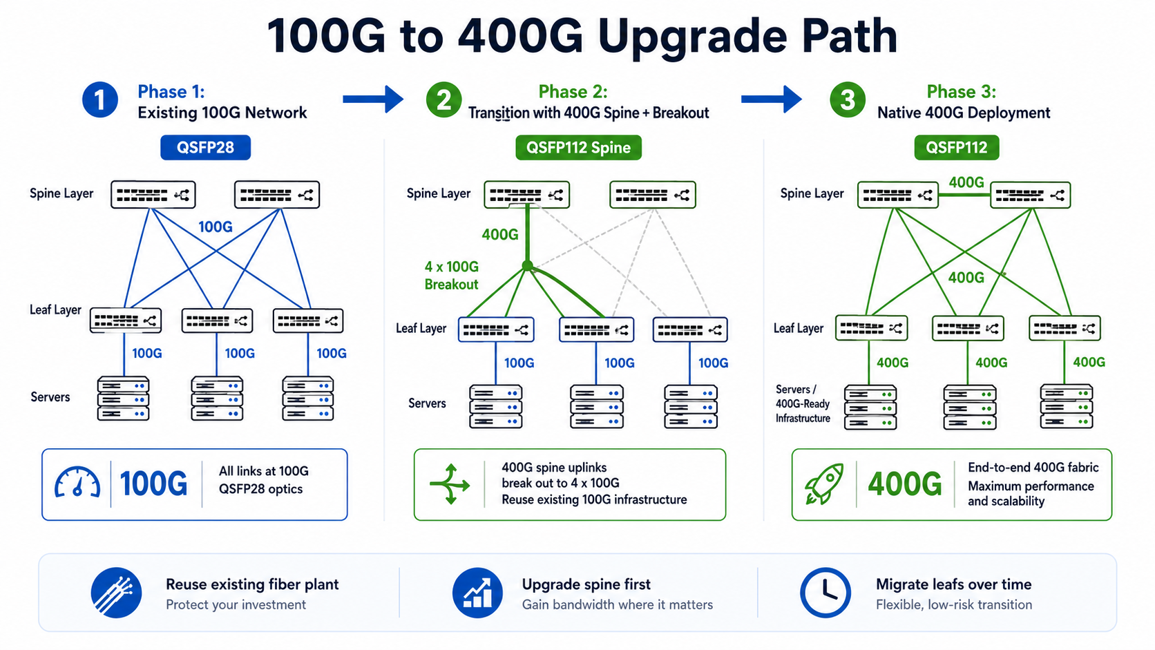
QSFP112 Breakout: The Bridge Strategy
The most underappreciated feature of QSFP112 for brownfield upgrades is breakout. On platforms that support port breakout, a 400G QSFP112 DR4 interface can be configured as four independent 100G DR links using appropriate breakout cabling and switch configuration. This means a single 400G spine port can fan out to four existing 100G leaf switches or servers without requiring 400G endpoints everywhere.
This is how most enterprises will actually transition. You upgrade the spine to 400G QSFP112, break out to 100G at the leaf, and replace leaf-side QSFP28 modules with QSFP112 only when servers and storage are ready.
Cost Considerations and TCO
QSFP112 modules cost more per unit than QSFP28, but the gap is narrowing. As of 2025, a 400G QSFP112 DR module averages around 120, down from roughly 120,down from roughly 195 in 2023. The real TCO driver is not module cost alone but the total infrastructure picture: switches, cabling, thermal upgrades, and power.
Organizations should model a 3-year TCO that includes:
- 1. Switch replacement or upgrade costs
- 2. Module procurement at the port count
- 3. New 400G-rated cabling
- 4. Additional power and cooling capacity
- 5. Reduced cost per gigabit as a normalization metric
Conclusion
QSFP112 and QSFP28 share the same physical form factor, but they serve fundamentally different phases of optical networking infrastructure. QSFP28 remains the reliable workhorse for 100G networks with mature ecosystems, low power draw, and universal compatibility. QSFP112 delivers 400G bandwidth within that same footprint but requires modern switch hardware with 112G PAM4 SerDes, capable thermal management, and a clear migration plan.
The most practical upgrade path for most organizations is neither wholesale replacement nor indefinite delay. It is a phased transition using QSFP112 breakout to bridge 100G leaf infrastructure while 400G capability is deployed at the spine. This approach preserves existing fiber investments, spreads capital expenditure over time, and avoids the disruption of a forklift upgrade.
Before committing to QSFP112, verify three things: your switch ASICs support 112G PAM4, your thermal budget handles the increased power draw, and your cabling plan accounts for either native 400G or breakout configurations. Getting these right ensures the transition from 100G to 400G is technically sound and economically justified.
Frequently Asked Questions (FAQ)
Is QSFP112 backward compatible with QSFP28?
In many cases, yes. QSFP112 ports on compatible platforms can support lower-speed QSFP28 and QSFP56 modules. However, compatibility depends on the switch ASIC, firmware, and vendor implementation. Always verify support with the equipment manufacturer before deployment.
Can I use a QSFP112 module in a QSFP28 port?
No. Although QSFP112 and QSFP28 share the same physical dimensions, QSFP28 ports are designed for 25G NRZ signaling and cannot support the 112G PAM4 electrical interface required by QSFP112 modules.
What is the main difference between QSFP28 and QSFP112?
The primary difference is bandwidth. QSFP28 supports up to 100Gbps using four 25G NRZ lanes, while QSFP112 supports up to 400Gbps using four 112G PAM4 lanes. QSFP112 also requires more advanced DSP processing, higher-speed SerDes, and improved thermal management.
Does QSFP112 require new switches?
Yes. To operate at 400G, the host platform must support 112G PAM4 SerDes. Existing QSFP28 switches cannot be upgraded to support native QSFP112 operation through optics alone. New-generation switch ASICs and network adapters are typically required.
Can QSFP112 be used for breakout applications?
Yes. Many 400G platforms support breakout configurations that divide a 400G interface into multiple lower-speed links, such as 4×100G or 2×200G connections. Breakout availability depends on the switch ASIC, operating system, and port configuration capabilities.
Why is QSFP112 important for AI and HPC networks?
AI training clusters and HPC environments generate massive east-west traffic between GPUs, storage systems, and compute nodes. QSFP112 provides 400G bandwidth within the familiar QSFP form factor, enabling higher port density and supporting modern platforms such as NVIDIA ConnectX-7, Spectrum-4, and Quantum-2.
Is QSFP112 replacing QSFP28?
Not immediately. QSFP28 remains widely deployed in enterprise and cloud networks because of its mature ecosystem and lower cost. However, QSFP112 is rapidly becoming the preferred choice for new 400G Ethernet and InfiniBand deployments, particularly in AI-driven data centers and high-performance computing environments.
Post Views: 709