PAM4 uses four distinct signal levels to represent 2-bit symbols; however, misidentifying an adjacent level can lead to multi-bit errors if left unaddressed. By employing Gray coding—where adjacent symbols differ by only a single bit—the most frequent decision errors are constrained to single-bit errors. This reduces the bit error rate (BER) and alleviates the burden on Forward Error Correction (FEC). This coding scheme serves as the foundational mechanism that ensures link reliability in 400G/800G optical modules when achieving high data rates via PAM4.
What Is PAM4?
From NRZ to PAM4
PAM4 stands for four-level pulse amplitude modulation. PAM4 became increasingly important as Ethernet data rates moved beyond 25G per lane. While NRZ remains widely used in lower-speed applications, PAM4 enables higher data rates per lane and is now common in 50G, 100G, and higher-speed Ethernet interfaces.
NRZ uses two signal levels, so each symbol carries exactly one bit. PAM4 uses four levels, so each symbol carries two bits. At the same baud rate, PAM4 delivers twice the data. A 53.125 Gbaud PAM4 lane carries 106.25 Gb/s, while an NRZ lane at that baud rate would only reach 53.125 Gb/s.
That efficiency is why the industry moved to PAM4. As Cisco explains, pushing NRZ past roughly 25 Gbaud runs into hard limits in PCB traces, connectors, and optical components. Halving the baud rate for a given data rate is how 400G and 800G became practical.
The Cost: Signal Integrity
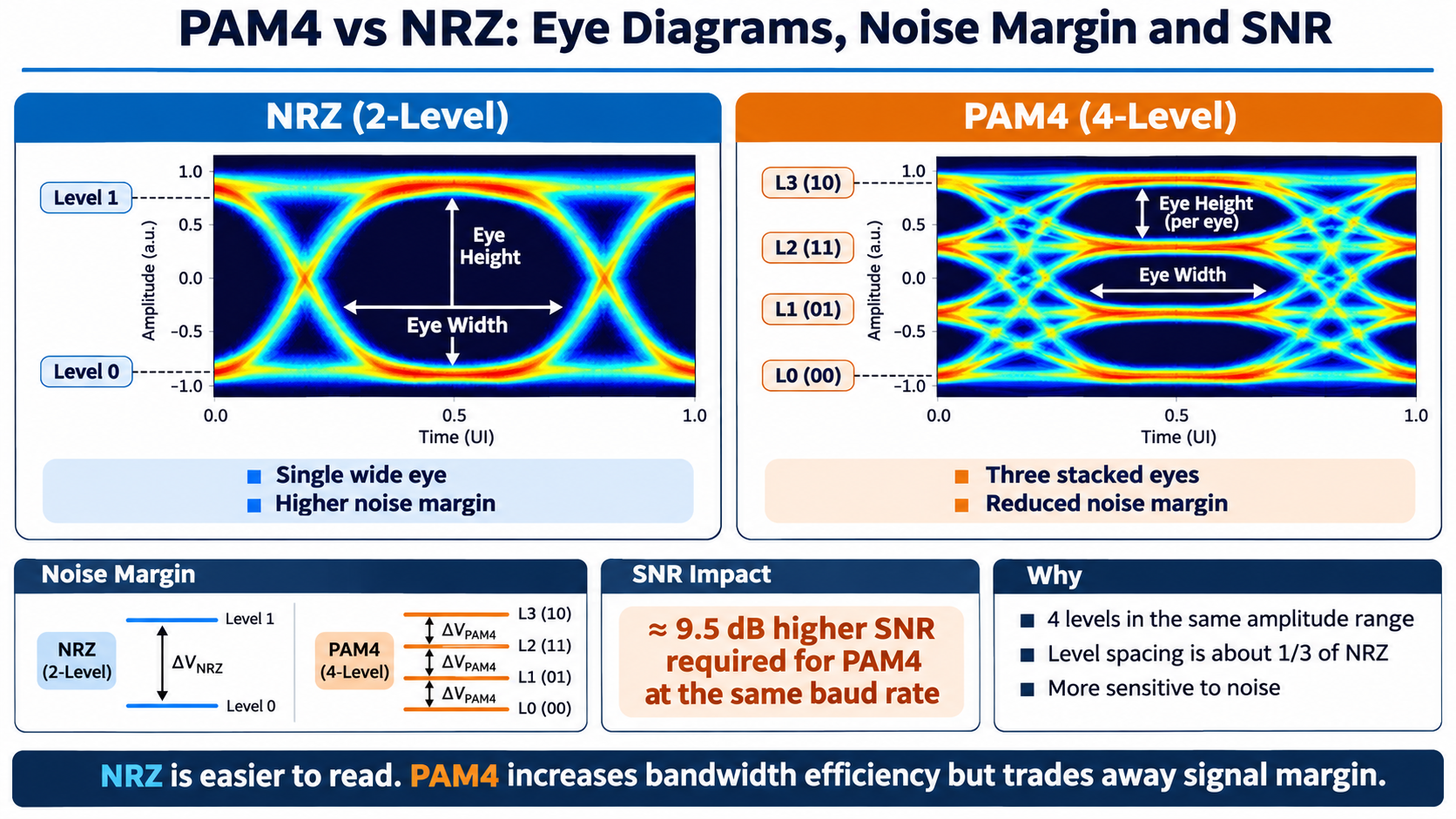
PAM4 uses four amplitude levels within the same overall signal swing, creating three eye openings. Ideally, the vertical spacing between adjacent levels is approximately one-third of the full signal swing, making PAM4 more sensitive to noise and signal distortion than NRZ.
PAM4 has a smaller vertical eye opening than NRZ because four signal levels share the same overall amplitude range. Under commonly used theoretical assumptions, this results in an approximately 9.54 dB SNR penalty compared with NRZ. The actual system-level penalty depends on the transmitter, receiver, and link conditions.
Here’s the trade-off at a glance:
| Parameter |
NRZ |
PAM4 |
| Signal levels |
2 |
4 |
| Bits per symbol |
1 |
2 |
| Eyes in the eye diagram |
1 |
3 |
| Relative eye height |
1× |
~1/3× |
| SNR penalty |
Baseline |
~9.54 dB |
| FEC Requirement |
Depends on the standard and application |
Commonly required in high-speed Ethernet applications |
This is where gray coding becomes essential. When noise pushes a symbol toward a neighboring level, what matters is how the four levels map to bits. A careless mapping turns every small mistake into two bit errors. A well-chosen mapping limits it to one.
What Is Gray Code?
Gray Code vs Binary Code
Gray code, also called reflected binary code, is a way of ordering numbers so that consecutive values differ by exactly one bit.
Standard binary counting doesn’t do this. In binary, 3 is 011, and 4 is 100. Moving from 3 to 4 flips all three bits at once. In a Gray-coded sequence, consecutive values change only a single bit, which makes the code far more forgiving when a physical signal lands near a boundary.
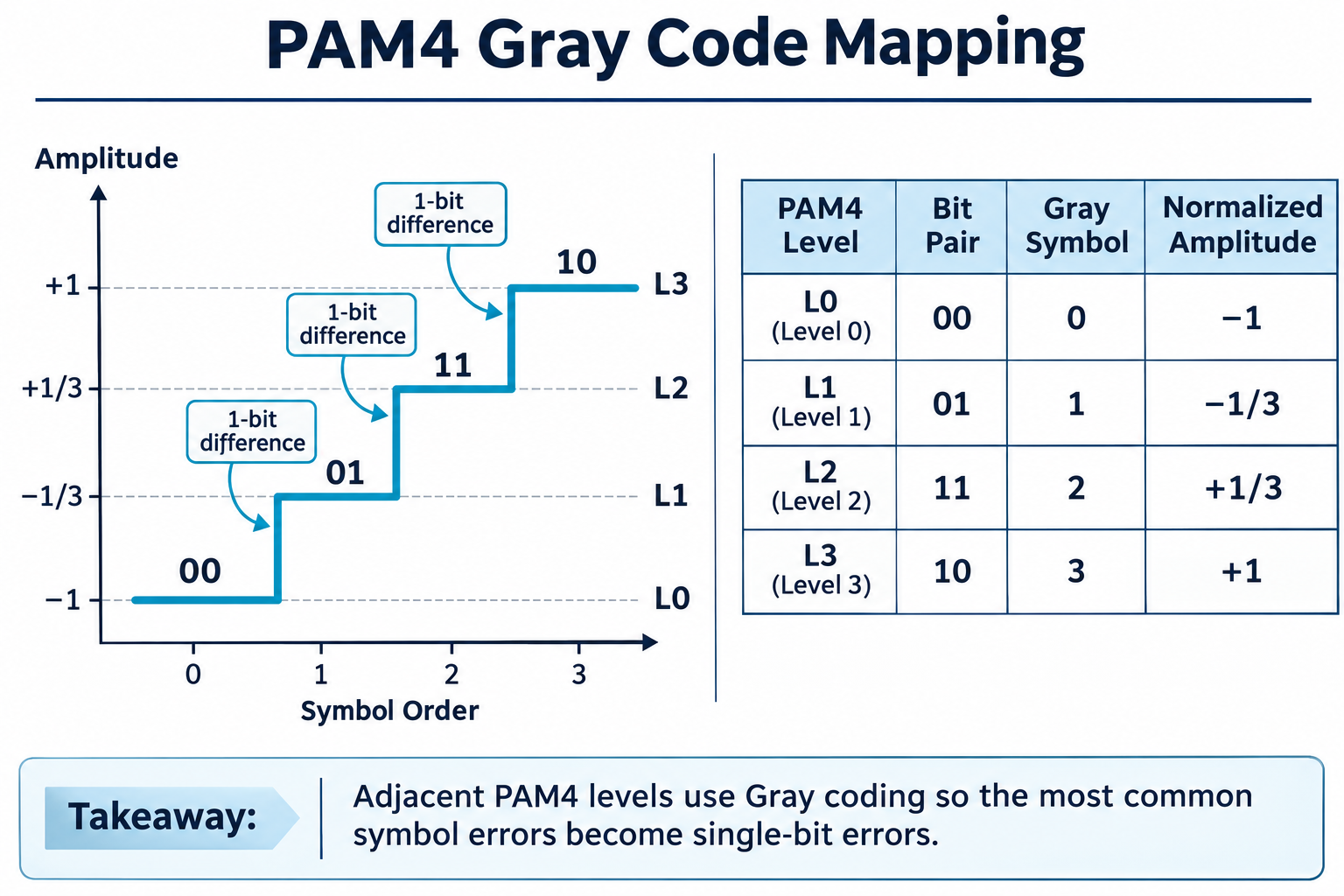
PAM4 borrows this idea for its four levels. The IEEE 802.3 standard defines a standard mapping relationship, as shown in the figure below.
The PAM4 Gray Code Mapping Table
| Bit Pair {MSB, LSB} |
Gray Symbol |
PAM4 Level (normalized) |
| 00 |
0 |
-1 (lowest) |
| 01 |
1 |
-1/3 |
| 11 |
2 |
+1/3 |
| 10 |
3 |
+1 (highest) |
Read down the middle column, and you’ll see the pattern: 0, 1, 2, 3 map to bit pairs 00, 01, 11, 10. Each neighboring level differs by exactly one bit.
Why PAM4 Uses Gray Coding
The Adjacent-Level Error Problem
Noise rarely flings a symbol all the way across the eye diagram. Far more often, a symbol gets misread as its immediate neighbor, one level up or down. That’s the error case Gray coding is built for.
Consider what happens without Gray coding. If levels 0, 1, 2, 3 mapped to plain binary 00, 01, 10, 11, then a symbol read as level 2 instead of level 1 would decode as 10 instead of 01. Two bits flip. One small amplitude error becomes two bit errors.
With the Gray mapping above, the same mistake decodes as 11 instead of 01. Only one bit flips. The damage is cut in half.
A Worked Example: One Level Off
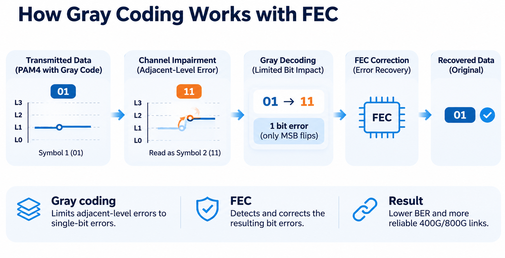
Let’s make it concrete. A 400G-DR4 module transmits the bit pair 01 on one optical lane. That’s Gray symbol 1, at the -1/3 level.
Noise on the channel pushes the received amplitude up by one level. The receiver reads symbol 2, which is the +1/3 level.
- With the Gray mapping, symbol 1 (01) misread as symbol 2 (11) flips only the MSB. One bit error.
- With a binary mapping, symbol 1 (01) misread as symbol 2 (10) flips both bits. Two bit errors.
Gray coding minimizes the number of bit errors caused by adjacent-level symbol errors. Since neighboring PAM4 levels differ by only one bit, a misclassification between adjacent levels typically results in a single-bit error rather than multiple-bit errors. However, errors involving non-adjacent levels can still produce multiple bit errors.
BER vs SER: Why Gray Coding Halves the Damage
This relationship shows up in the numbers. Engineers track both symbol error rate (SER) and bit error rate (BER). Since each PAM4 symbol carries two bits, adjacent-level errors under Gray coding typically produce one bit error per erroneous symbol. In this case, the BER is approximately half the SER. However, the actual relationship depends on the distribution of symbol errors.
How Gray Coding Works With FEC
Why PAM4 Needs FEC
PAM4’s compressed eyes mean raw, uncorrected BER is far worse than NRZ’s. Where a good NRZ link might target 10⁻¹² or better, PAM4 links routinely run at pre-FEC BERs of 10⁻⁴ to 10⁻⁶. They survive because every 400G and 800G link ships with forward error correction.
A widely used FEC scheme in high-speed Ethernet is KP4 FEC, based on Reed-Solomon RS(544,514) coding. It provides error-correction capability that helps improve link reliability under noisy transmission conditions.
Gray Coding Makes FEC More Effective
Gray coding and FEC serve complementary purposes. Gray coding reduces the number of bit errors caused by adjacent-level PAM4 decision errors, while Reed-Solomon FEC operates on multi-bit code symbols to detect and correct errors. Together, they help improve the reliability of high-speed PAM4 transmission.
The result is fewer corrupted FEC symbols per link error, which means FEC corrects more of the damage before it reaches the MAC. In short: Gray coding keeps errors small and local, and FEC cleans up what’s left.
Pre-FEC BER Targets
The standards set explicit pre-FEC BER thresholds. They’re worth knowing when you validate a link:
- 100GBASE-SR2: BER ≤ 10⁻⁵
- 50GBASE-SR: BER ≤ 2.4×10⁻⁴
- 200GBASE-SR4 / DR4 / FR4: BER ≤ 2.4×10⁻⁴
These numbers come from Tektronix’s PAM4 signaling guide. If your link clears them, the Gray-coded symbols plus FEC will deliver a clean post-FEC result. If it doesn’t, no amount of clever mapping will save you.
A note on testing. Marcus, a hardware validation lead at a module vendor, spent two weeks chasing a 400G link that kept failing FEC under thermal load. The culprit wasn’t the Gray mapping or the DSP.
It was a marginal host connector adding crosstalk that pushed the pre-FEC BER just past 2.4×10⁻⁴. Gray coding kept single-bit errors dominant, but FEC can only correct so much. The fix was connector tuning, not silicon.
PAM4 Gray Coding in Real Optical Modules
400G Transceivers
A 400G QSFP-DD or OSFP module isn’t a single PAM4 lane. It’s an architecture built around the same Gray-coded symbols.
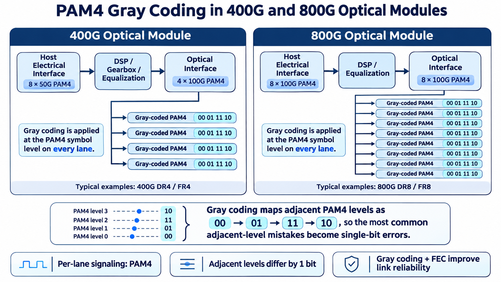
Many 400G QSFP-DD and OSFP modules use an 8-lane 50G PAM4 electrical host interface. For optical interfaces such as 400G-DR4 and 400G-FR4, the transmitted data is carried over four 100G PAM4 optical lanes. The exact electrical and optical lane configurations depend on the module design and interface standard. Depending on the module architecture, a DSP may perform functions such as gearbox processing and signal equalization.
800G Transceivers
800G-DR8 uses eight 100G PAM4 optical lanes, each operating at approximately 53.125 Gbaud. Gray coding is used for PAM4 symbol mapping, while FEC provides additional error-correction capability as specified by the applicable Ethernet standard.
That’s why Ascent Optics treats signal integrity and FEC validation as core parts of module qualification, not afterthoughts. If you’re mapping out an 800G deployment, see our 800G and 1.6T optical transceiver guide for the form-factor and lane details.
PAM4 vs Coherent: Where Gray-Coded PAM4 Fits
It’s easy to blur PAM4 and coherent together, but they solve different problems. PAM4 is a direct-detect format. PAM4 is commonly used in direct-detection optical systems, where information is encoded through four optical intensity levels. Coherent optical systems use more complex modulation formats, such as QPSK and QAM, and recover both amplitude and phase information. Gray coding can also be used in coherent modulation schemes to reduce bit errors caused by adjacent constellation-point decision errors.
Coherent detection is different. It mixes the incoming signal with a local laser and recovers phase and polarization, using constellations like QPSK and QAM instead of PAM4’s four intensity levels. That buys far more reach and spectral efficiency, at the cost of power and complexity.
The practical split is distance. Gray-coded PAM4 dominates short-reach, cost-sensitive links inside and between data centers. Coherent technology is widely used in metro and long-haul applications, while direct-detection PAM4 is common in short-reach data center links. For a deeper comparison, our coherent optical modules guide walks through when each technology is the right call.
PAM4 Optical Modules From AscentOptics
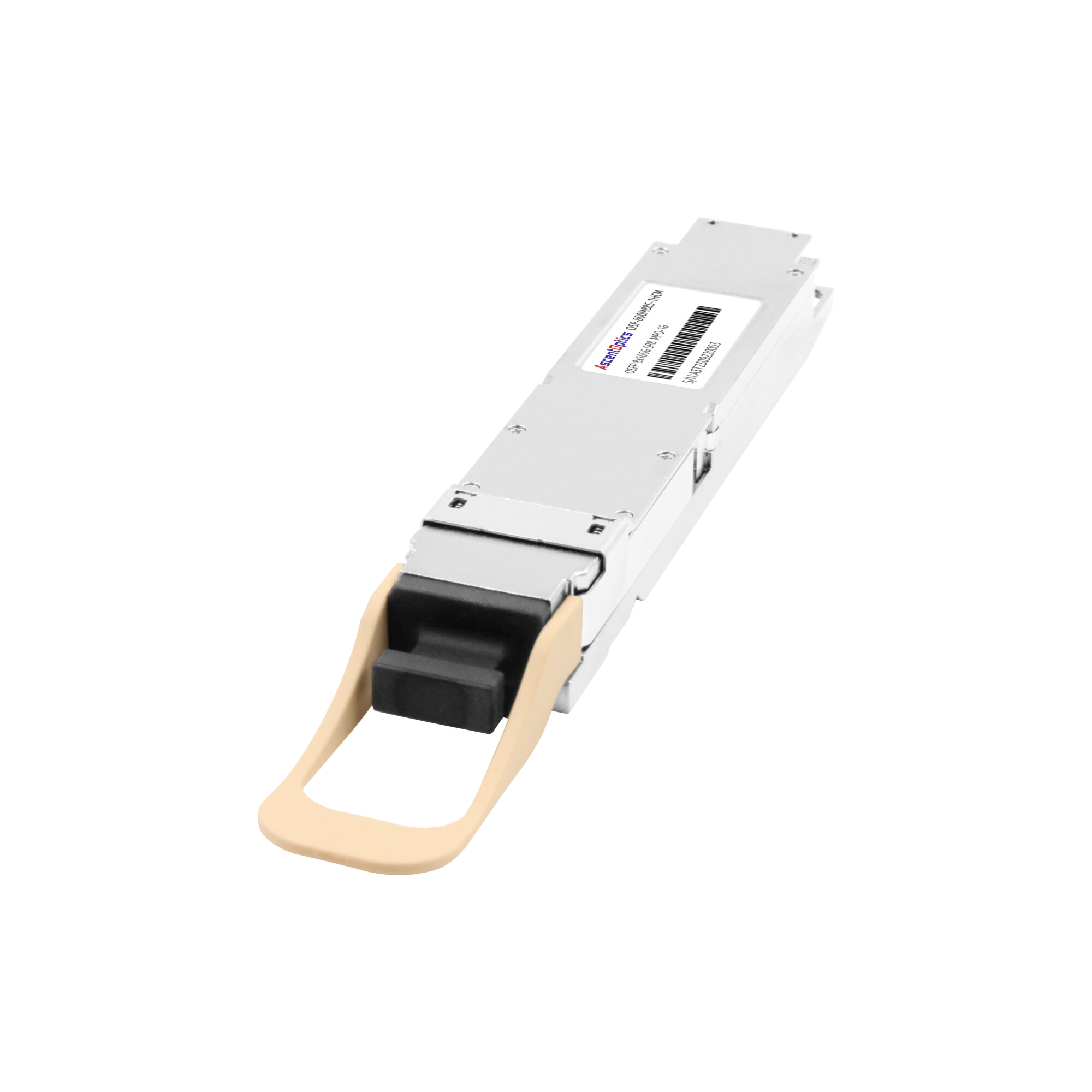
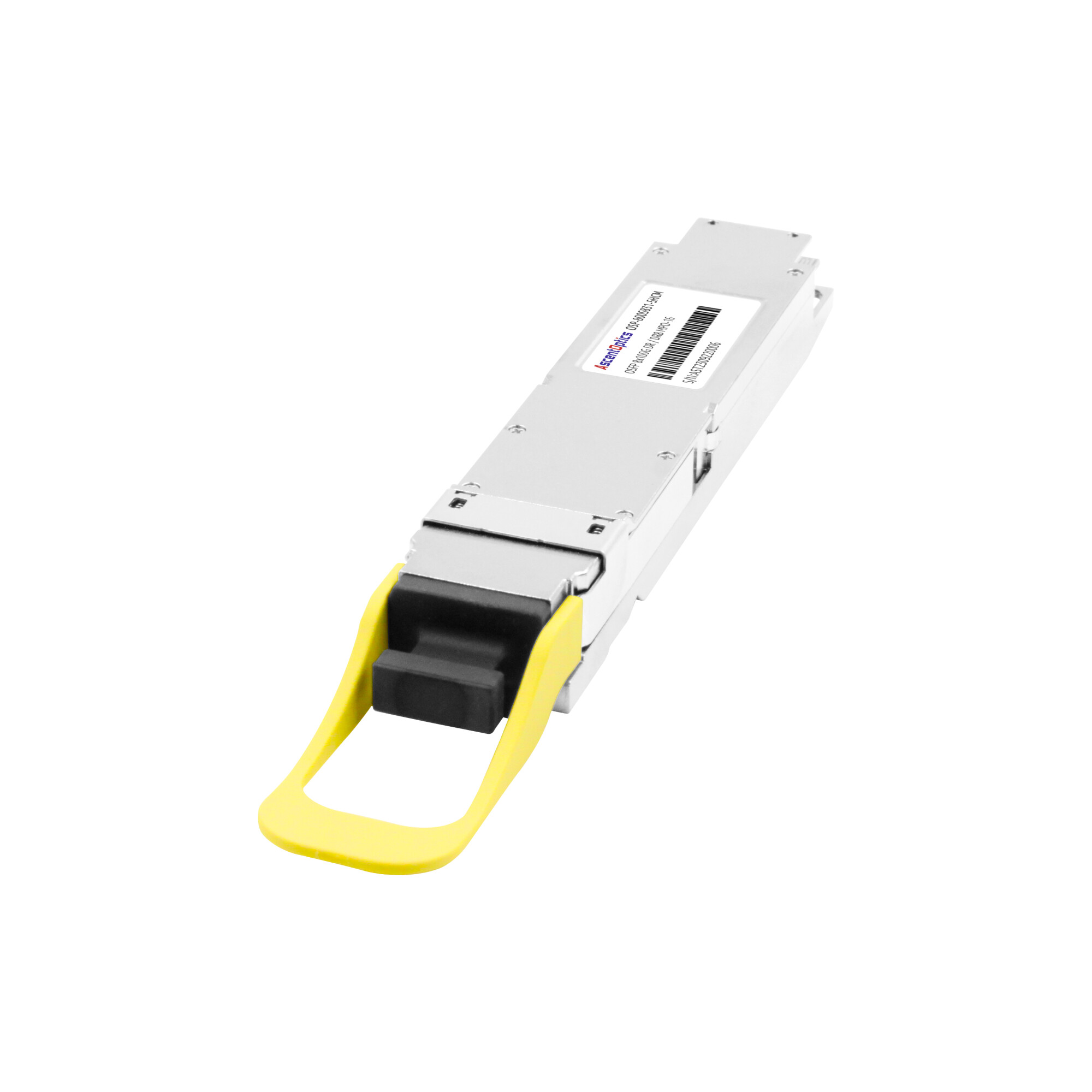
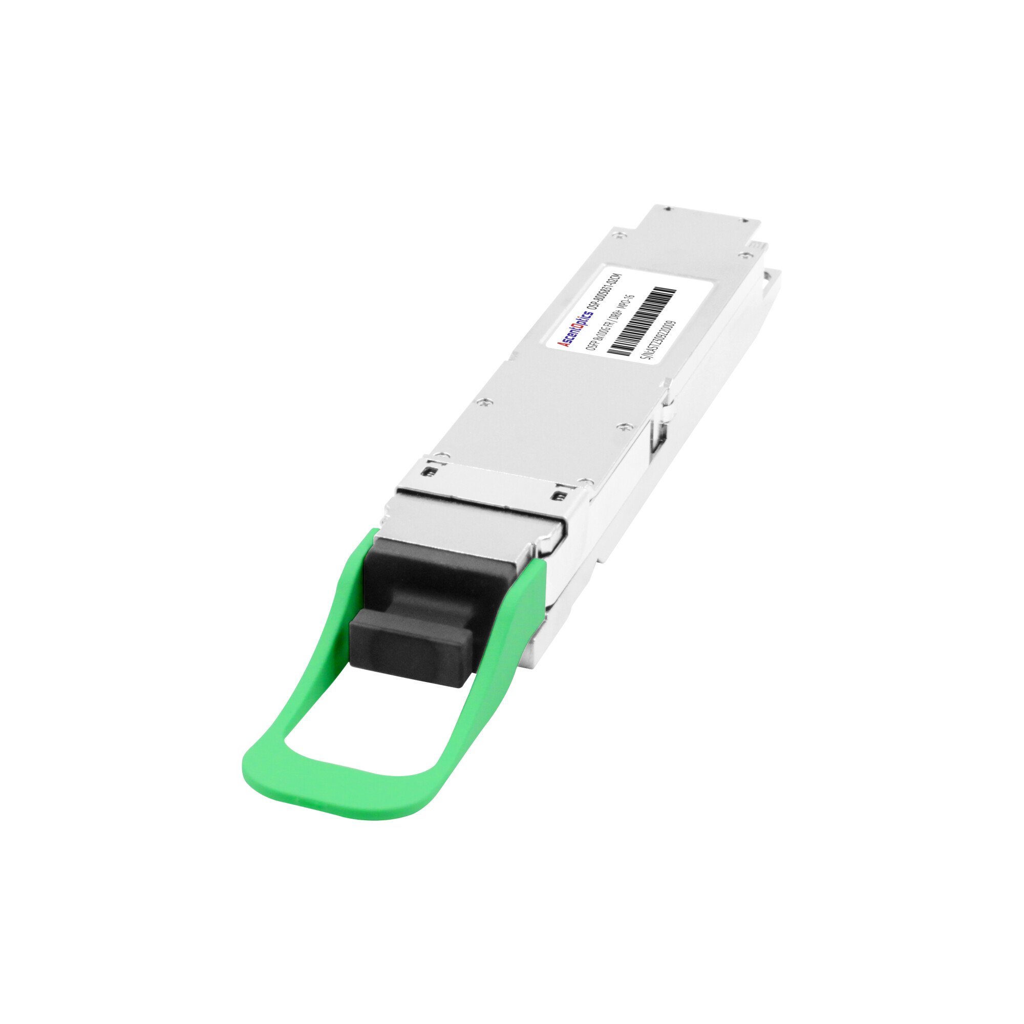
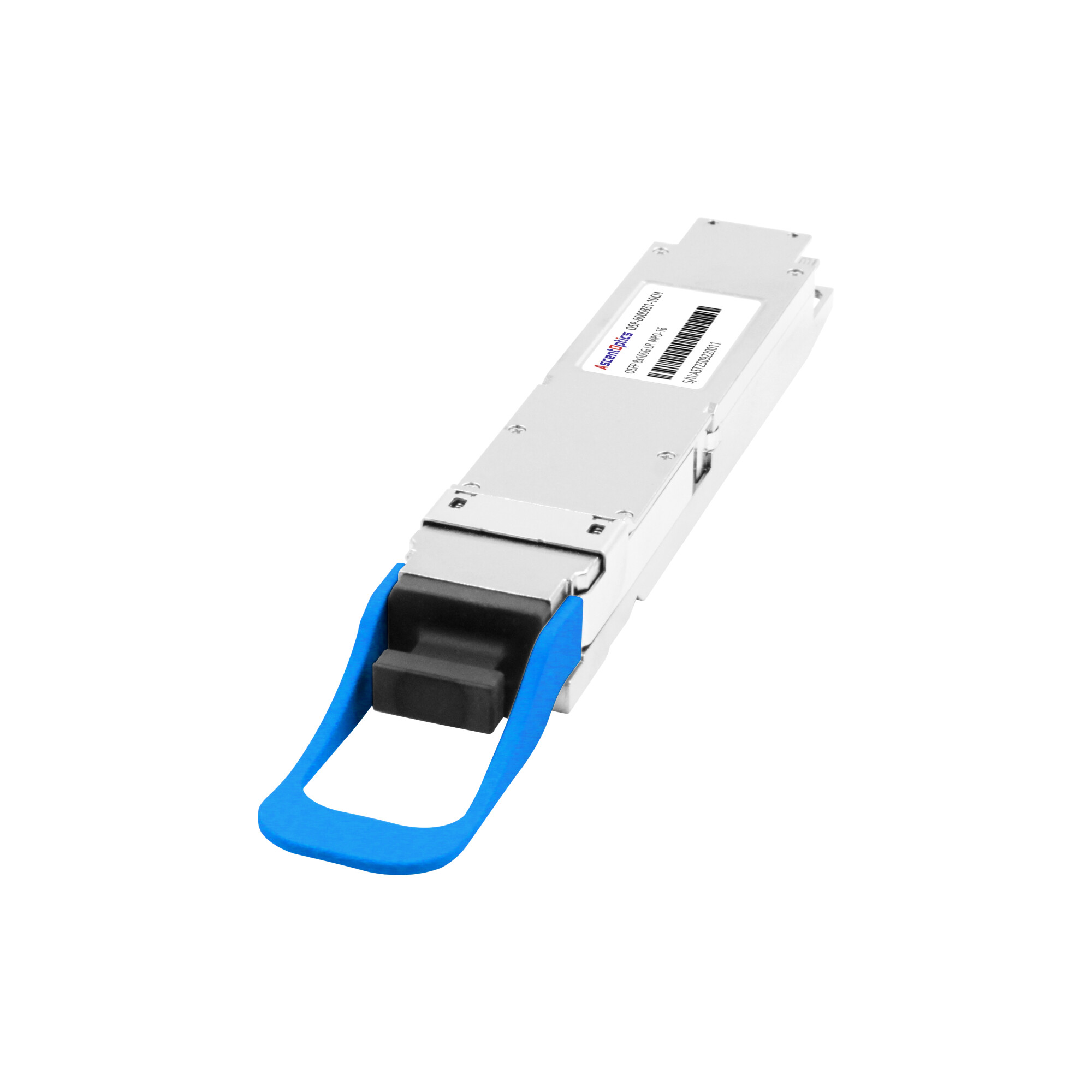
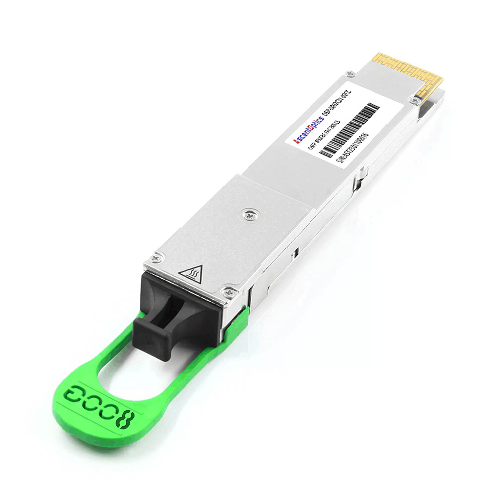
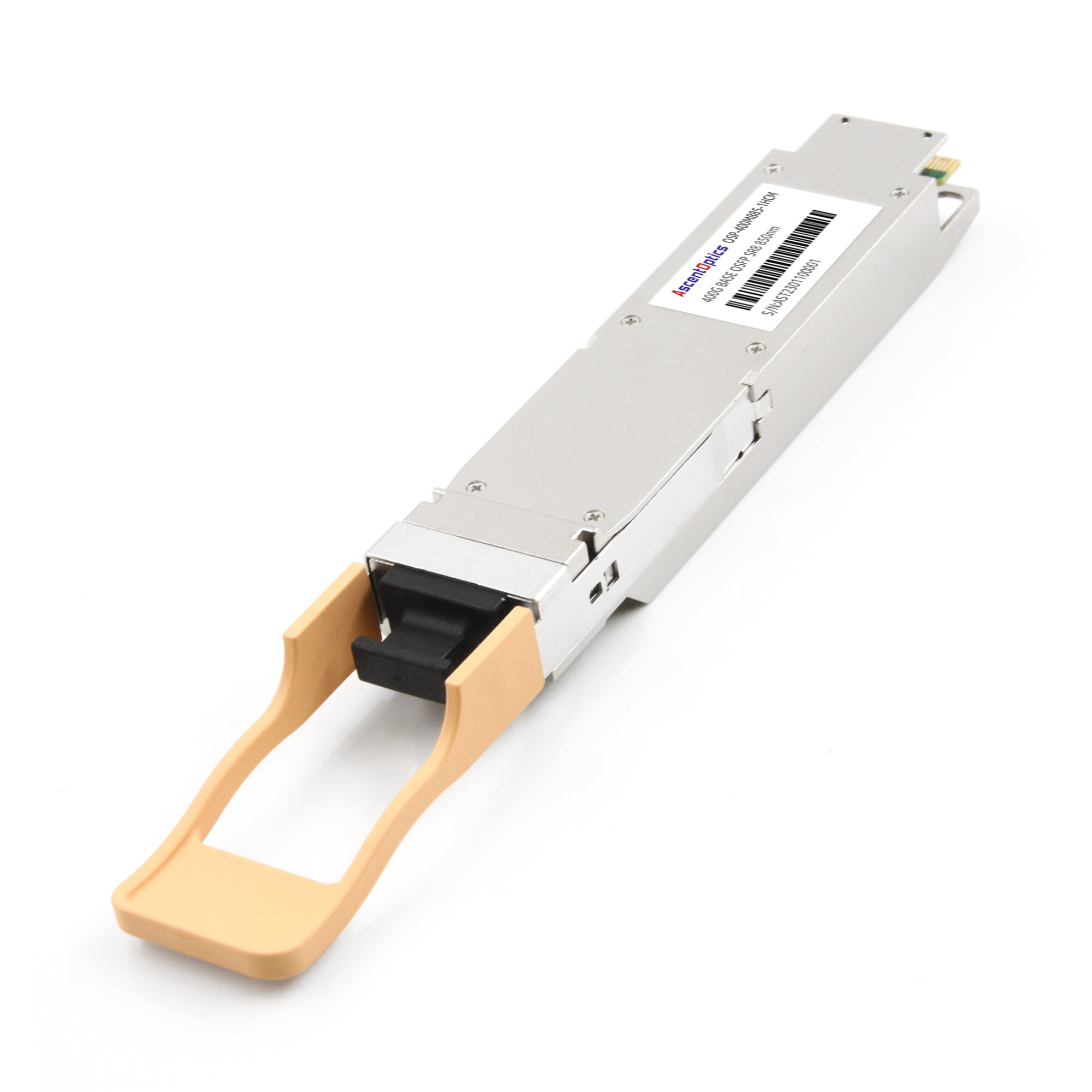
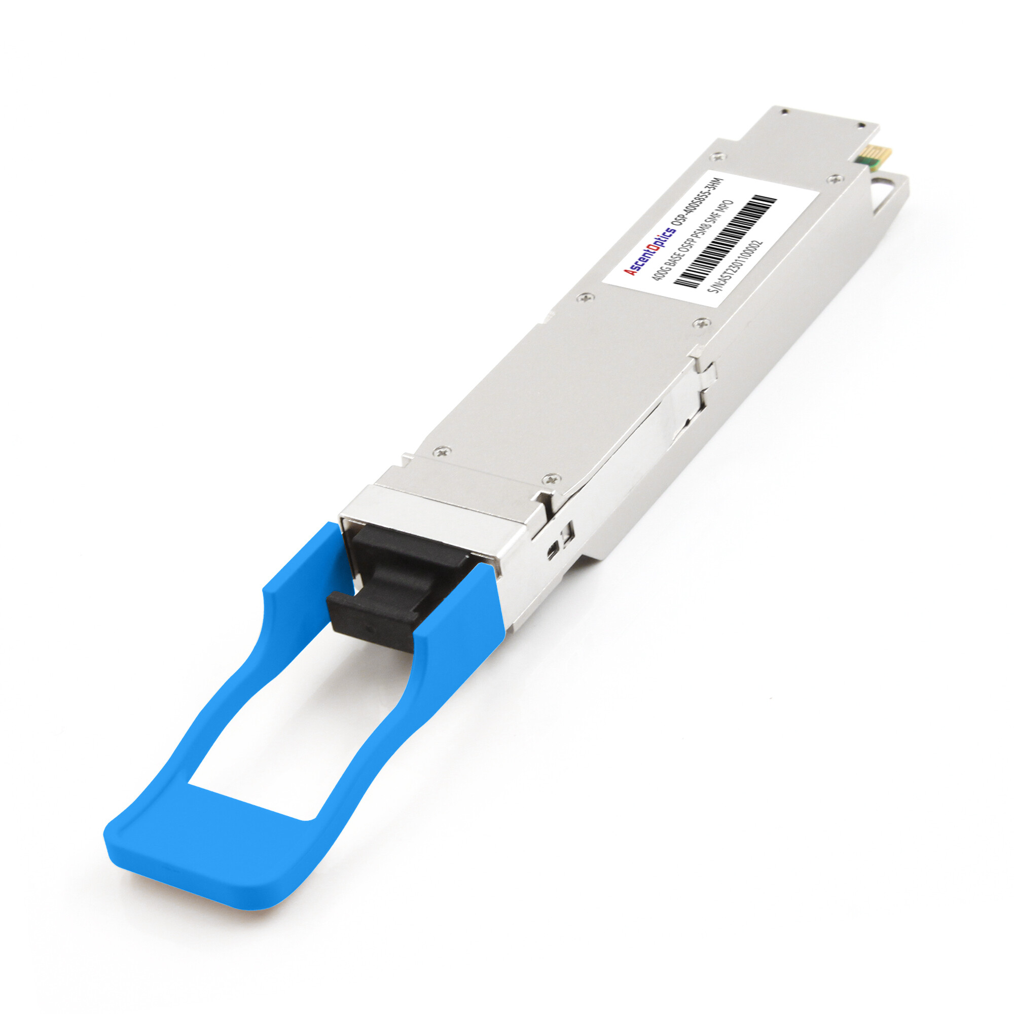
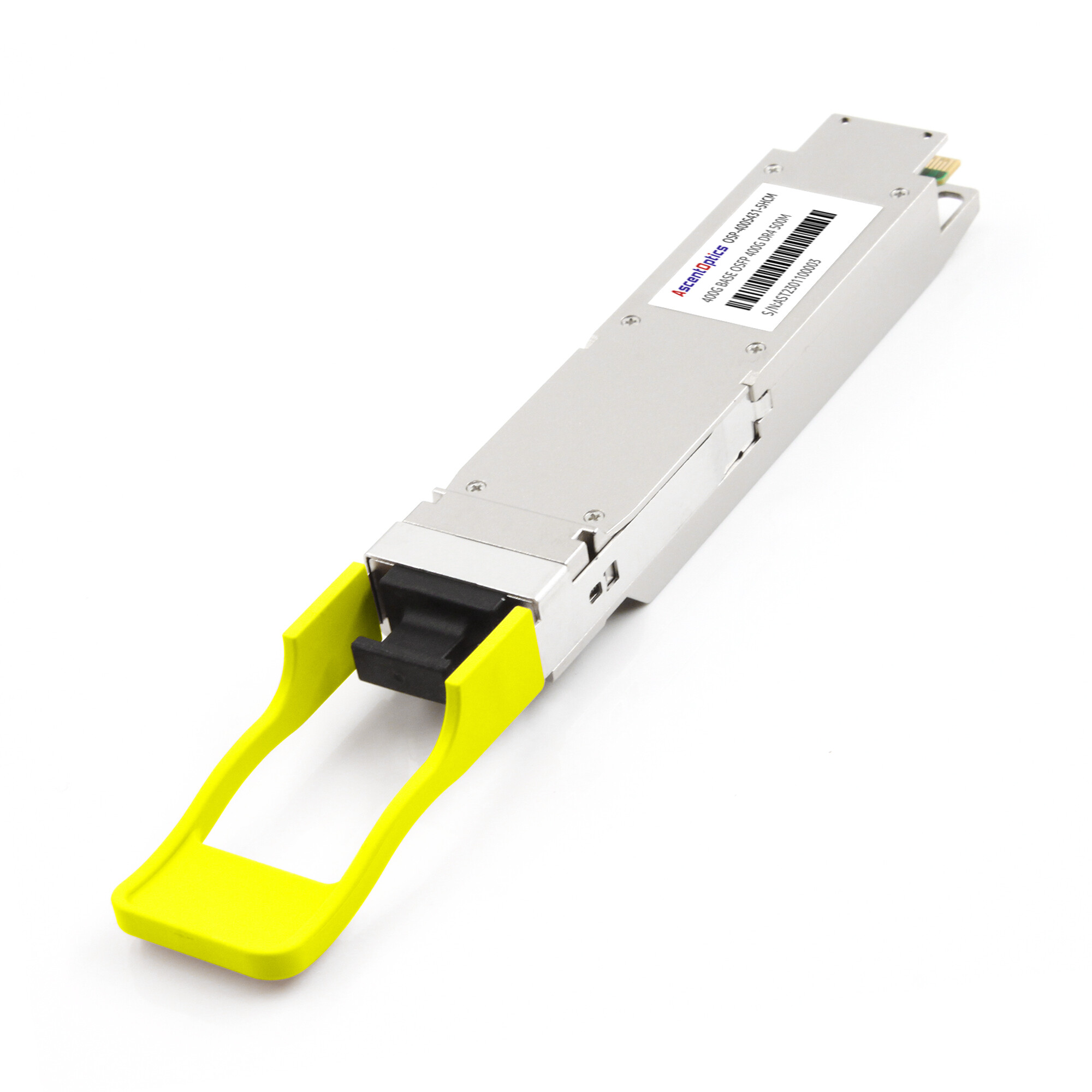
Ascent Optics builds PAM4-based optical modules for 400G and 800G networks, in QSFP-DD and OSFP form factors. Our portfolio spans 400G-DR4, 400G-FR4, and 800G-DR8/FR8 modules, each qualified for the signal-integrity and FEC performance these links demand.
For power and thermal planning on dense 400G/800G builds, our QSFP-DD power consumption guide covers the DSP and FEC overhead you’ll need to budget for.
Conclusion
PAM4 gray code is a small piece of the physical layer with an outsized effect on link reliability. The four levels map to bit pairs 00, 01, 11, 10 so that neighboring levels differ by one bit. When noise misreads a symbol as its neighbor, the damage is a single bit error, not two.
Here’s what to remember:
- PAM4 doubles data rate over NRZ but pays a ~9.54 dB SNR penalty.
- Gray coding halves the bit errors from the most common, adjacent-level symbol mistakes.
- FEC (KP4 RS(544,514)) corrects the rest, and Gray coding keeps those errors inside single FEC symbols.
- Pre-FEC BER targets like 2.4×10⁻⁴ are the numbers to validate against.
The next time you watch a pre-FEC BER counter on a 400G or 800G link, the PAM4 gray code is part of why the link holds. Understanding it means you can design, validate, and troubleshoot high-speed optical links with confidence.
FAQs
What is PAM4 Gray Coding?
PAM4 Gray coding maps four signal levels to bit pairs (00, 01, 11, 10), ensuring that adjacent levels differ by only one bit.
Why does PAM4 use Gray Coding?
Gray coding reduces bit errors caused by adjacent-level misclassification, improving the reliability of PAM4 signal transmission.
What is the difference between Gray Code and Binary Code?
In standard binary counting, consecutive values may differ by multiple bits. In Gray coding, adjacent values differ by only one bit.
How does Gray Coding reduce BER in PAM4?
When a receiver misidentifies a PAM4 symbol as an adjacent level, Gray coding typically limits the resulting error to one bit instead of two.
What is the relationship between PAM4 Gray Coding and FEC?
Gray coding reduces bit errors caused by adjacent-level mistakes, while FEC detects and corrects transmission errors. They work together to improve link reliability.
Do 400G and 800G optical transceivers use PAM4 Gray Coding?
Yes. PAM4 with Gray-coded symbol mapping is widely used in high-speed optical interfaces, including 400G and 800G applications.
Does Gray Coding eliminate transmission errors?
No. Gray coding reduces the bit errors caused by adjacent-level misclassification, but it cannot eliminate noise or all symbol errors. FEC provides additional error correction.
Post Views: 97