Traditional Data Center Network Architecture
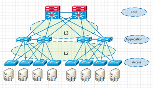
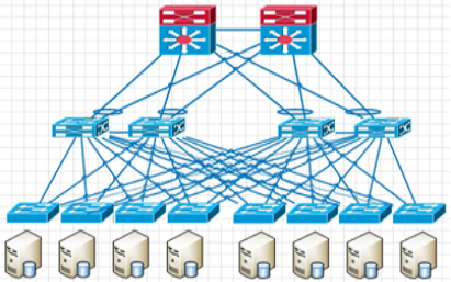
The new network architecture in traditional data centers usually follows a 3-tier structure, (campus networks are also generally 3-tier structures) Cisco calls this structure the hierarchical interconnection network model, containing three layers.
Core core layer: Provides high-speed forwarding and connectivity for multiple aggregation layers.
Aggregation Layer: This layer connects to the access switches and also provides other services (FW, SLB, etc.)
Access layer: This layer physically connects to the servers and is usually located at the top of the cabinet. It is also known as the Top-of-Rack(ToR) switch.
A three-tier architecture is illustrated as follows.
The Convergence Layer is the demarcation point of the network. The L2 network is below the convergence switch, while L3 network is above it. Each group of convergence switch represents a pod, which is divided into the service-specific area module. within each pod, there is one or more VLAN network, and each POD corresponds to be a broadcast domain.
This architecture is simple to deploy and (vlan+xstp) technically mature.
VLAN, Xstp
Reasons for using VLAN( Virtual Local Area Network), xstp.
1. BUM (Broadcast, Unknown Unicast, Multicast)
The VLAN technology divides a large physical Layer 2 domain into several small logical Layer 2 domains called VLAN. Within the same VLAN, Layer 2 communication is allowed, without VLAN isolation. This ensures that the broadcast range is limited to the VLAN itself and does not spread to the entire physical Layer 2 domain.
The VLAN also simplifies management, improves security, etc.
2. Loop and loop formed by the broadcast storm
If it is a Layer 3 architecture composed of single device and single link, there is no loop and the broadcast brought by the loop. However, the reliability of this network is poor since there are no backup devices and links. If a device or link fails, all hosts under the failure point will lose connection to the network.
To improve network reliability , redundant devices and links are usually used (as shown above), resulting in the formation of loops. Layer 2 networks belong to the same broadcast domain, and broadcast messages are repeatedly and continuously transmitted within the loop, which can lead to the formation of a broadcast storm in wireless loops, causing instant port blocking and equipment paralysis.
To prevent loops and ensure the reliability of the network, redundant devices and links can be converted into backup devices and backup links. Under normal circumstances, redundant devices and links are blocked and do not participate in forwarding data messages. Only when the current forwarding device, port, link fails and cause network failure, will the redundant devices and links be activated to restore the network function. These automatic control protocols are called loop-breaking protocols, the most commonly used is STP (Spanning Tree Protocol) with RSTP, MSTP collectively known as XSTP protocol.
Server Virtualization
The development of virtualization has significantly impacted the requirements of data center network architecture. With technologies like virtual machine dynamic migration, it is essential to ensure that the IP and MAC addresses of virtual machines remain unchanged before and after migration, which requires the network before and after virtual machine migration to be inside the same Layer 2 domain, or even across different geographic areas and between different server rooms. As a result, the scope of Layer 2 networks in data centers has expanded, leading to the emergence of the new field topic of large Layer 2 networks.
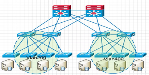
Traditional network architecture of the second layer is not big up
The general traditional network architecture is based on business characteristics and is divided into different modules, with corresponding VLAN divisions in different regions. Cross-pod migration will inevitably change the IP address, which does not meet the requirements of dynamic migration of virtual machine without interruption:
VLAN issues
One of the core ideas of VLAN is to control the size of broadcast storms by dividing VLANs to reduce the scope and size of the Layer 2 domain.
If all servers are included in the same VLAN without other isolation means, it is equivalent to expanding the broadcast domain to a large size, which is contrary to the original purpose of dividing VLANs.
With the rise of public cloud and the popularity of IaaS(Infrastructure as a Service) model, a “multi-tenant” environment has become a necessary basic capability for cloud networks. In traditional Layer 2 networks, the maximum number of tenants supported by VLAN is 4K, which can no longer keep up with the rapid development of business.
xSTP questions
The convergence speed of loop technology is slow, xSTP needs to block off redundant devices and links, which reduces the bandwidth utilization of network resources and greatly limits the scale of Layer 2 networking.
Realization of large second floor
Traditional Layer 2 technology cannot achieve a true large-scale Layer 2 network, so we have to come up with another way. Then the technology gurus show their skills and come up with a lot of solutions.
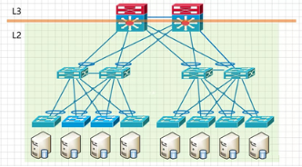
1、Virtual switch technology
As the core problem of Layer 2 networks is the loop issue, which often arises with redundant devices and links, loops can be eliminated by merging multiple devices and links into one, which is the network device virtualization technology.
The so-called network device virtualization technology is to combine two or more physical network devices that are redundant with each other and virtualize them into one logical network device that is presented as only one node in the entire network.
Network device virtualization combined with link aggregation technology can transform the original multi-device multi-link structure into a logical single-device single-link architecture, eliminating the appearance of loops, and therefore no longer subject to the restrictions of loop-breaking protocols, thus enabling the realization of a large Layer 2 network.
The main technologies for network device virtualization can be broadly classified into three categories: stacking technology for box devices, stacking technology for modular devices, and mixed stacking technology between box/box. There are Huawei’s CSS, iStack, and SVF, CISCO’s VSS and FEX, and H3C’s IRF, etc.
Network device virtualization solutions also have certain disadvantages.
1) These protocols are private to the manufacturer, so only equipment from the same manufacturer can be used to form the network.
2) Limited by the size of the stacking system itself, the largest stacking/clustering can support access to 10-20,000 hosts, which may sometimes be insufficient for mega data centers. But for general data center, it is still sufficient.
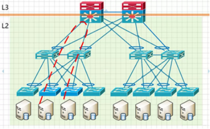
East-west L3 traffic, regardless of whether it is under an access layer switch or not, needs to go through the core switch with L3 function. If the east-west traffic is large, it will waste valuable core switching resources and multi-layer forwarding will also increase the network transmission delay.
Secondly, the BUM (Broadcast-, Unknown Unicast, Multicast) storms in shared L2 broadcast domains increase significantly with the size of the network, which eventually affects normal network traffic.
2、Tunnel technology
Tunneling technology can also addresses the loop problem in Layer 2 networks, but the focus is not on eliminating or blocking loops, but on how to avoid loops in the logical forwarding path when there are physical loops.
The core idea of this technology is to introduce the routing and forwarding method of Layer 3 networks into Layer 2 networks by inserting additional frame headers before Layer 2 messages, and using route calculation to control the data forwarding throughout the network. This not only prevents broadcast storms under redundant links, but also enables ECMP (Equal Cost Multi-path). This allows the Layer 2 network to scale up to the entire network without being limited by the number of core switches. Of course, this requires the switch to change the traditional MAC-based Layer 2 forwarding behavior and use a new protocol mechanism for Layer 2 message forwarding.
New protocols include TRILL, FabricPath, SPB, etc.
The TRILL protocol encapsulates a TRILL frame header outside the original Ethernet frame, and then encapsulates a new outer Ethernet frame to achieve transparent transmission of the original Ethernet frame, which can be forwarded by the TRILL switch through the Nickname identifier in the TRILL frame header, which, like a route, can be collected, synchronized and updated through the IS-IS routing protocol.
TRILL and SPB these technologies are the main CT vendors to promote the large layer 2 network technology solutions.
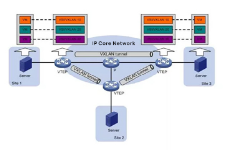
3、Overlay network
An overlay network is a virtual network built on top of an existing network (Underlay network). The term “existing network” refers to the network where the previous switch is located, as long as it is an IP network. Overlay network is an L2 network built on top of the L3 network. In other words, as long as the L3 network can cover a certain area, the L2 network of the overlay network can also cover that area.
By using tunnel encapsulation, the original Layer 2 messages from the source host are encapsulated and transmitted transparently in the existing network. After reaching the destination, they are decapsulated to get the original messages and forwarded to the destination host, thus realizing Layer 2 communication between hosts.
Through encapsulation and decapsulation, it is equivalent to overlaying a large Layer 2 network on top of the existing base network, hence referred to as an Overlay, also know as NVo3.
The core of the Overlay solution is a point-to-multipoint tunnel encapsulation protocol that abstract away the structure and details of the intermediate network and virtualizes the entire intermediate network as a “giant Layer 2 switch”. In this virtual network, each host is directly connected to a port on this “giant switch”. Each host is directly connected to a port of this “giant switch”. Thus, hosts do not need to be concern with the internal details of how the traffic is forwarded in the underlying network.
Overly technology is independent of the bearer network and can fully utilize existing infrastructure networks to achieve the large-scale Layer 2 networks. It has advantages in supporting SDN and multi-tenancy aspects, and is currently the most popular technology of the large-scale layer 2 networks. It can achieve a large-scale layer 2 network for the entire data center, even interconnect large-scale layer 2 network across data center. However, Overly technology consists of two control levels: the Overlay network and the Underlay bearer network, making management maintenance, and fault location relatively more complex. The operation and maintenance work is also relatively more extensive.
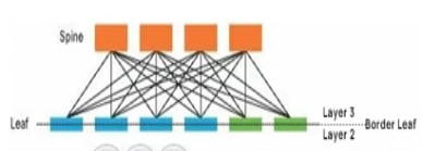
VXLAN with Spine/Leaf architecture.
Spine/Leaf networks extend the access and aggregation layers. A host can communicate with a host on another leaf-branch switch through the leaf-branch switch (leaf), and it is a separate channel. This network can greatly improve the efficiency of the network, especially for high performance computing clusters or high frequency traffic communication devices.
East-West traffic does not need to go through the core.
Post Views: 7,786