If you are planning a similar upgrade, you already know the pressure. Data center bandwidth demands are climbing fast. AI workloads, hyperscale cloud growth, and high-performance computing clusters all push networks from 100G toward 400G. The challenge is choosing the right optical module for each link. For short-reach connections over multimode fiber, QSFP112 SR4 stands out as the most cost-effective path to 400G.
What Is QSFP112 SR4?
400GBase-SR4 Standard Overview
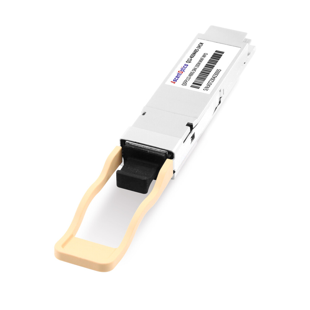
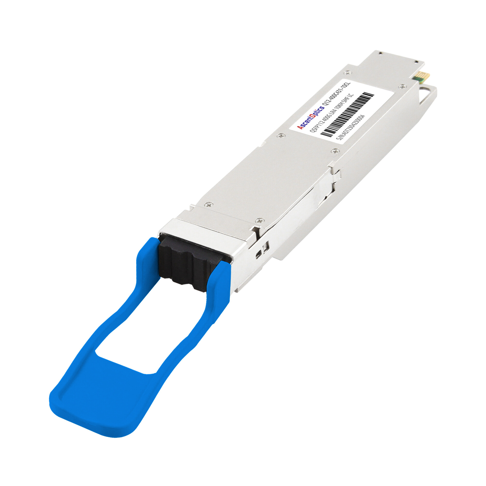
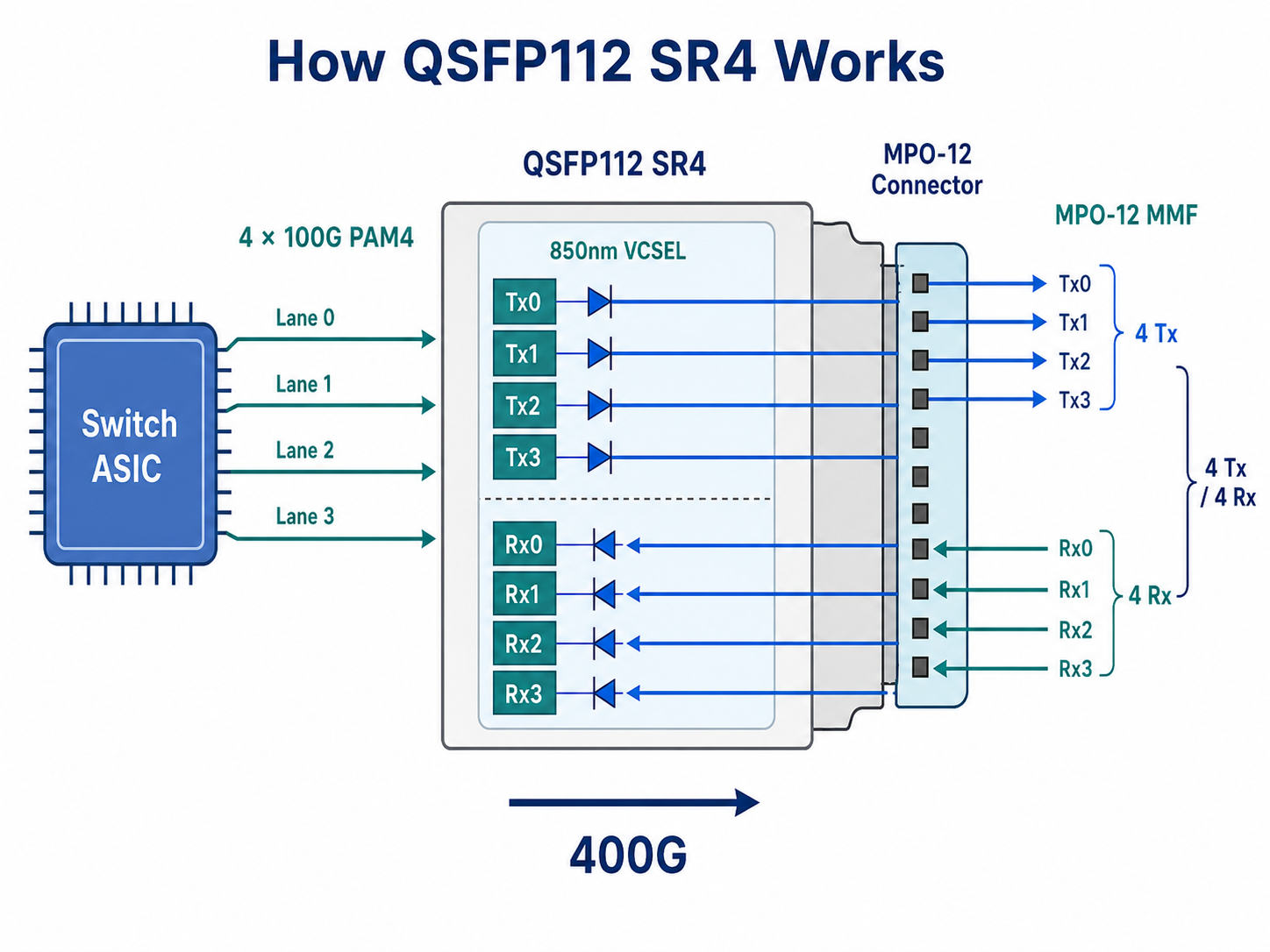
QSFP112 SR4 is a 400G optical transceiver module designed for short-reach data transmission over multimode fiber. QSFP112 is a form-factor specification defined by industry MSA groups rather than a separate IEEE optical standard. The optical characteristics of QSFP112 SR4 follow the IEEE 400GBASE-SR4 specification while using a 4×112G electrical interface. It transmits four parallel optical lanes, each carrying 100 Gbps, to achieve a total data transmission rate of 400 Gbps. The module complies with the IEEE 802.3cm standard for 400GBase-SR4 and operates at an 850nm wavelength using a VCSEL laser array.
The SR4 designation tells you exactly what this module does. “SR” means short reach. “4” indicates four optical lanes. Combined with the QSFP112 form factor, you get a hot-pluggable module that delivers 400G bandwidth in the same physical footprint as legacy QSFP28 modules.
How QSFP112 SR4 Fits the QSFP112 Ecosystem
QSFP112 SR4 shares the same electrical interface as other QSFP112 variants. All QSFP112 modules use four electrical lanes at 112 Gbps PAM4 signaling. The difference lies in the optical engine. SR4 uses parallel multimode optics, while DR4, FR4, and LR4 variants target single-mode fiber at progressively longer distances.
This shared electrical foundation means switches do not need different ASICs for each optical variant. A QSFP112 port can accept SR4, DR4, FR4, or LR4 modules interchangeably, provided the switch firmware supports the target protocol.
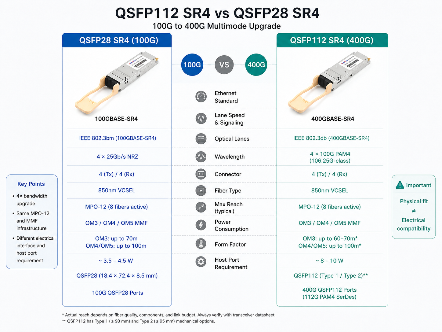
QSFP112 SR4 vs. QSFP28 SR4
The jump from QSFP28 SR4 to QSFP112 SR4 multiplies bandwidth by four while preserving the same fiber infrastructure. Both modules use MPO-12 connectors and multimode fiber. Both operate at 850nm. The critical difference is lane speed. QSFP28 SR4 uses four lanes at 25 Gbps NRZ. QSFP112 SR4 uses four lanes at 112 Gbps PAM4.
Physical compatibility is maintained. QSFP112 SR4 fits into the same QSFP112 cages that may already exist in your switches. However, electrical compatibility requires host ASICs that support 112 Gbps PAM4 signaling. A QSFP112 SR4 module will not function in a QSFP28 port, even though the module physically fits.
QSFP112 SR4 Technical Specifications
Optical Parameters
QSFP112 SR4 optical transceiver modules deliver reliable performance within clearly defined parameters. The 850nm VCSEL array generates four independent optical channels. Each channel supports PAM4 modulation, which carries two bits per symbol compared to one bit per symbol in NRZ encoding.
Reach varies by fiber grade. Over OM3 multimode fiber, QSFP112 SR4 supports distances up to 70 meters. OM4 extends this reach to 100 meters. OM5 can provide additional performance margin and, in some vendor implementations, may support reaches beyond 100 meters. However, IEEE 400GBASE-SR4 specifications typically define 100 meters as the standard maximum reach.
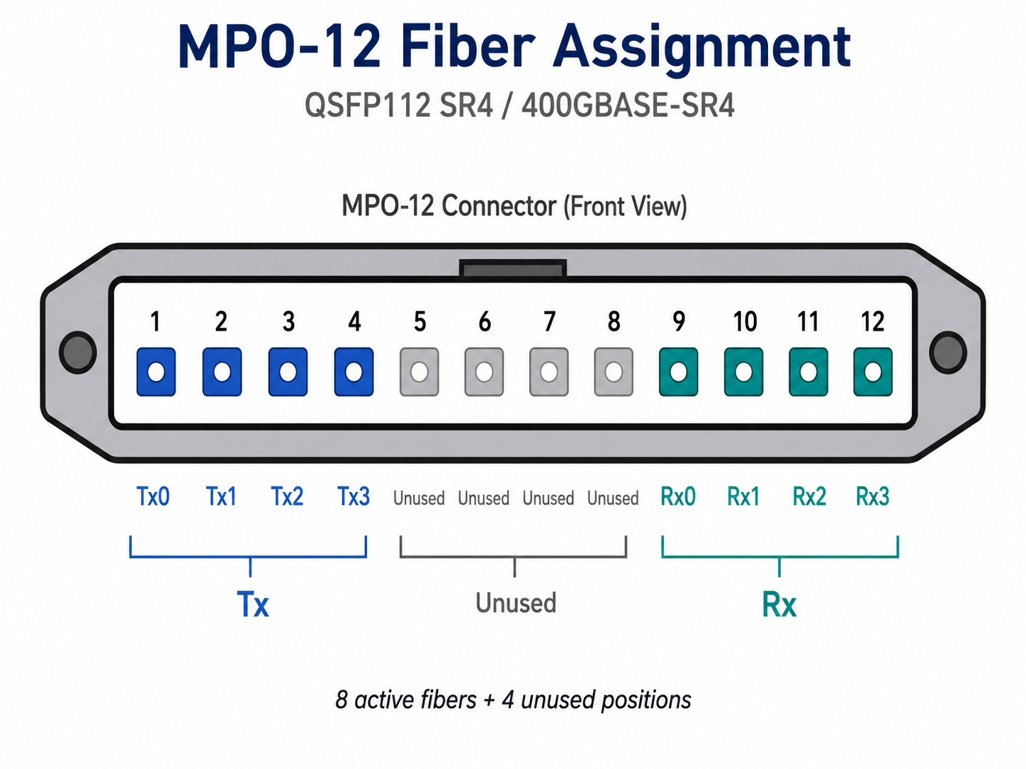
The module connects via an MPO-12 connector. This parallel fiber interface uses eight active fibers, four for transmit and four for receive, plus four unused positions in the MPO-12 array. Optical loss budgets are tight at 400G. The total channel insertion loss must stay within IEEE 802.3cm limits, typically 1.9 dB for OM3 and up to 2.3 dB for OM4/OM5 links.
Electrical and Power Specifications
The electrical side of QSFP112 SR4 operates at 4 x 112 Gbps PAM4. This signaling rate requires host SerDes that comply with OIF-CEI-112G-VSR-PAM4 specifications. Forward error correction is mandatory. 400GBase-SR4 uses KP4 Reed-Solomon FEC to maintain signal integrity across the optical link.
Power consumption is a key advantage. QSFP112 SR4 modules typically draw 8 to 10 watts. This is notably lower than QSFP-DD SR4 equivalents, which often consume 10 to 14 watts. For a 32-port switch, choosing QSFP112 over QSFP-DD can reduce optical power consumption by 64 to 128 watts. Those savings translate directly to lower cooling costs and improved thermal headroom.
Digital optical monitoring via CMIS 5.0 or 5.2 provides real-time visibility into module health. Network operators can track transmit and receive power levels, temperature, supply voltage, and lane-specific error rates through standard I2C interfaces.
Physical Dimensions
QSFP112 SR4 maintains the standard QSFP form factor of 18.4 mm by 89.4 mm by 8.5 mm. This consistency enables high port density in modern switches. A 1RU switch can host up to 32 QSFP112 ports, delivering 12.8 terabits per second of switching capacity.
Thermal design matters at this density. QSFP112 SR4 modules are available in flat-top and finned-top variants. Finned-top designs increase surface area for airflow cooling, which helps in thermally constrained racks. Flat-top modules may be preferable when adjacent ports are spaced tightly or when custom heat sinks are used.
Fiber Infrastructure Requirements for QSFP112 SR4
Multimode Fiber Types and Reach
Choosing the right multimode fiber is essential for reliable QSFP112 SR4 deployment. OM3 fiber supports distances up to 70 meters. This makes OM3 suitable for intra-rack connections where servers sit directly below a top-of-rack switch. For longer runs within the same row, OM4 extends reach to 100 meters.
OM5 wideband multimode fiber represents the next evolution. OM5 supports distances up to 150 meters with QSFP112 SR4. Beyond the reach extension, OM5 is optimized for shortwave wavelength division multiplexing. While the current 400GBase-SR4 does not use SWDM, future standards may leverage OM5’s wider bandwidth to support even higher data rates over the same fiber plant.
When evaluating your existing infrastructure, remember that fiber age and installation quality matter. Older OM4 cables installed before 2015 may not meet current performance specifications. Microbends, tight radius turns, and poor termination practices can all reduce effective reach below theoretical maximums.
MPO-12 Connector Requirements
QSFP112 SR4 uses an MPO-12 connector for parallel optical transmission. Understanding connector details prevents deployment failures. The MPO-12 interface contains twelve fiber positions in a single row. For 400GBase-SR4, positions 1 through 4 typically handle transmit signals, positions 9 through 12 handle receive signals, and positions 5 through 8 remain unused.
Polarity is critical. Three polarity methods exist. Method A uses straight-through mapping. Method B reverses the fiber positions at one end. Method C pairs fibers in a crossover pattern. For QSFP112 SR4 deployments, Method B is most common in data center trunk cabling. However, your specific cable plant may use Method A or Method C. Mismatched polarity is one of the most common causes of link failures in parallel optics deployments.
APC polish is strongly recommended for MPO connectors at 400G speeds. UPC polish can produce higher back-reflection, which affects signal quality in high-speed PAM4 systems. While some vendors specify UPC for multimodal applications, APC provides better performance margins and is increasingly the default for new installations.
Fiber Plant Assessment Checklist
Before deploying QSFP112 SR4 modules, verify that your fiber plant meets four key criteria. First, measure actual fiber distances. Do not rely on cable labels or building plans. Use an optical time-domain reflectometer or calibrated light source to confirm every link length stays within the specification for your fiber grade.
Second, calculate the total optical loss budget. Add insertion losses from connectors, patch panels, and splices. Compare the total against the module’s receiver sensitivity specifications. If your calculated loss exceeds the budget, the link will not operate reliably.
Third, inspect the connector end-faces. Contamination is the leading cause of optical link failures. Even microscopic dust particles can block 850nm signals at 400G data rates. Use a fiber inspection probe to check every MPO end-face before connection.
Fourth, confirm polarity mapping. Document whether your trunk cables use Method A, B, or C. Ensure that patch cords at both ends maintain consistent polarity from transmitter to receiver.
Reusing Existing Multimodal Infrastructure
Many data centers already have multimode fiber plants installed for 100G QSFP28 SR4 links. The good news is that QSFP112 SR4 can often reuse this infrastructure. The MPO-12 connector, the 850nm wavelength, and the multimode fiber type all remain compatible.
OM3 plants can support QSFP112 SR4 for intra-rack links under 70 meters. If your existing OM3 runs are longer, upgrading to OM4 or OM5 may be necessary. OM4 plants are the sweet spot for most QSFP112 SR4 deployments, supporting 100-meter links that cover the majority of intra-row connections.
When reusing existing fiber, pay special attention to connector wear. MPO connectors have a limited number of mating cycles. Heavily used patch panels may have worn pins or degraded ferrules that were adequate at 100G but problematic at 400G. Replacing high-wear patch cords is often the cheapest insurance against intermittent link failures.
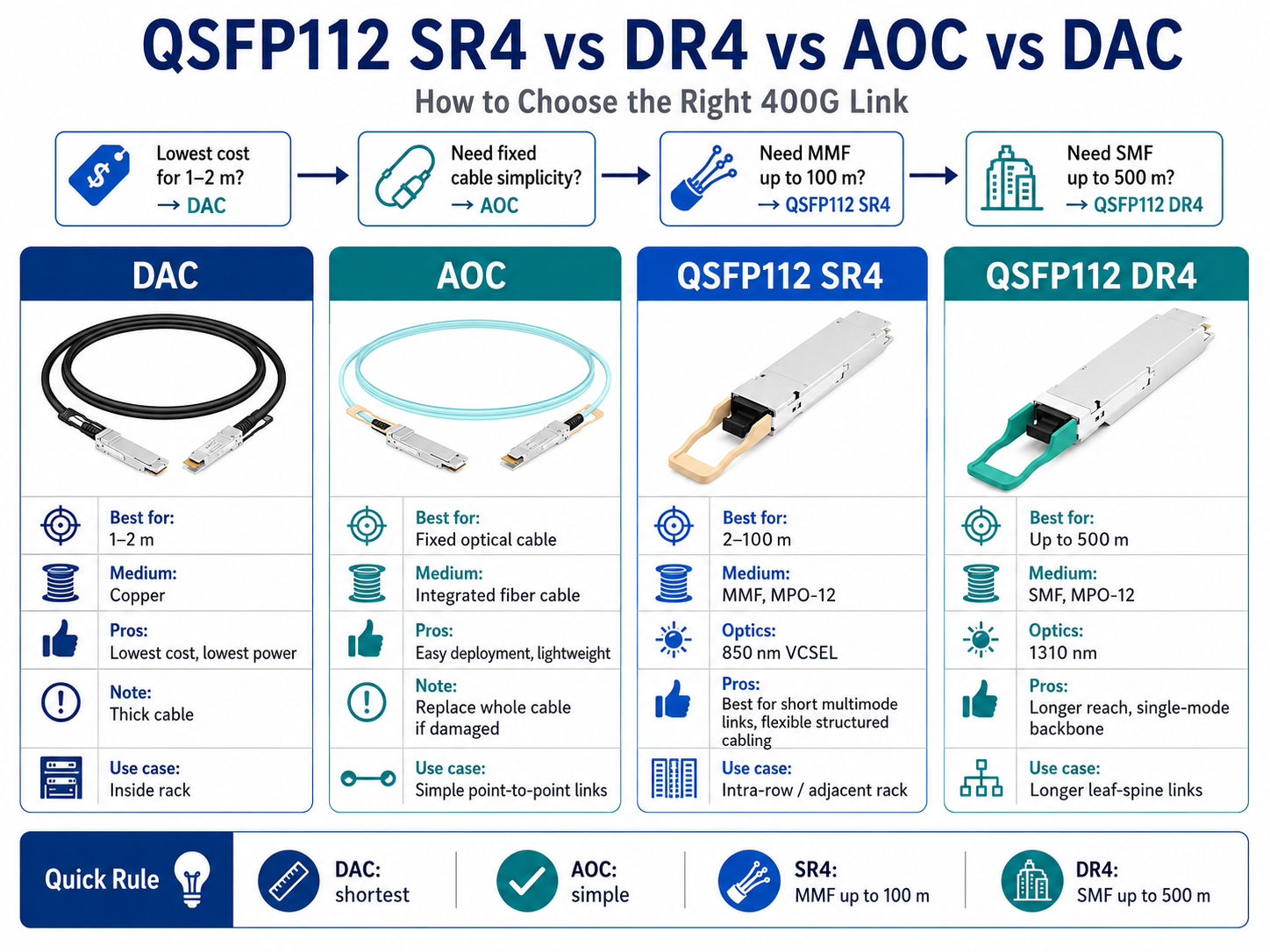
QSFP112 SR4 vs. Alternative 400G Short-Reach Options
The choice between SR4 and DR4 comes down to distance and fiber type. QSFP112 SR4 supports up to 100 meters over OM4 multimode fiber using an MPO-12 connector. QSFP112 DR4 extends reach to 500 meters over single-mode fiber, also using MPO-12.
Cost favors SR4 for short links. VCSEL-based multimode transceivers cost significantly less than silicon photonics-based single-mode equivalents. For links under 100 meters where multimode fiber already exists, SR4 is the clear economic choice. DR4 becomes necessary only when distances exceed the SR4 reach or when a single-mode fiber is already installed.
Power consumption is comparable between the two variants, both falling in the 8 to 12-watt range. The real differentiator is fiber infrastructure. Deploying DR4 in a multimode environment requires a complete fiber plant replacement. Deploying SR4 in a single-mode environment is possible, but it wastes the cost advantage of single-mode fiber for longer-reach applications.
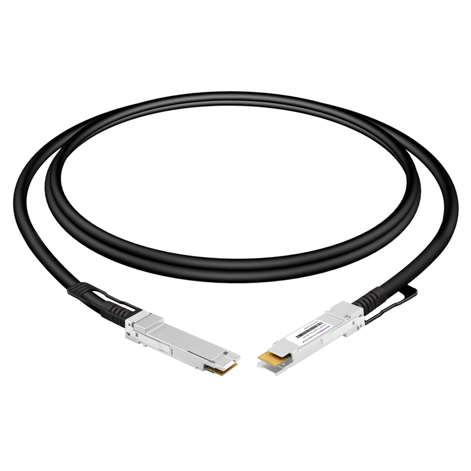
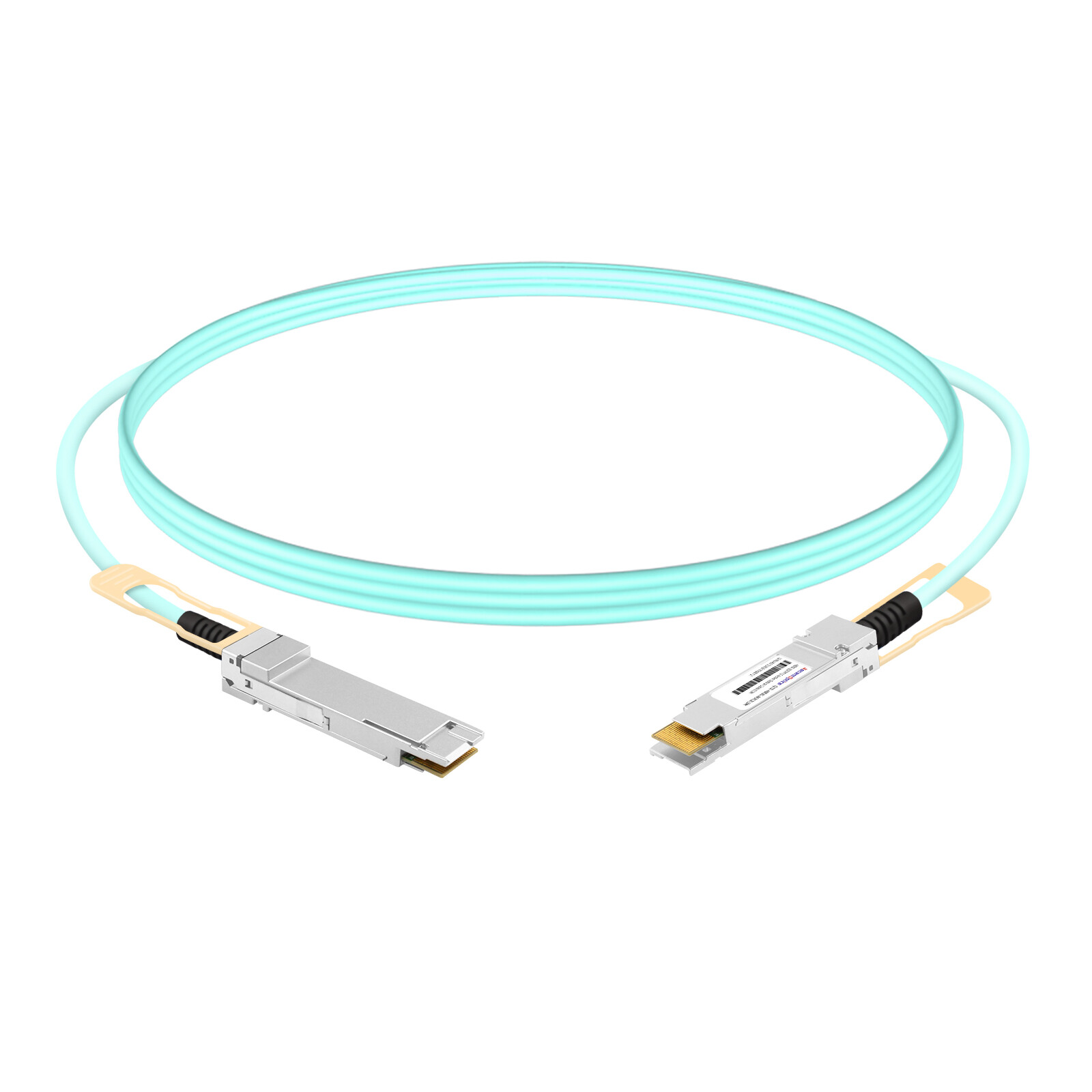
Active optical cables offer an alternative to discrete transceivers and fiber combinations. AQSFP112-to-QSFP112 AOC integrates the optical transceiver and fiber into a single assembly. This approach eliminates separate fiber management and guarantees optical compatibility.
AOCs excel in controlled environments with predictable cable lengths. Data centers with standardized rack layouts often prefer AOCs for top-of-rack to server connections because they simplify inventory and reduce installation errors. However, AOCs cannot be field-repaired. If the cable is damaged, the entire assembly must be replaced.
QSFP112 SR4 with discrete MPO trunk cables provides more flexibility. Custom cable lengths are easy to source. Damaged cables can be replaced individually without discarding transceivers. For data centers with existing fiber patch panels and structured cabling, discrete SR4 modules integrate more naturally into the existing management infrastructure.
Direct-attach copper cables represent the lowest-cost option for 400G connectivity. Passive DAC supports distances up to 1 meter. Active DAC extends this to 2 meters. Both options use copper conductors rather than optical signaling.
DAC cables are ideal for top-of-rack connections where servers sit immediately adjacent to switches. They consume no optical power and generate minimal heat. However, DAC thickness and bend radius constraints make cable management challenging in dense racks. For links longer than 2 meters, DAC is not an option.
QSFP112 SR4 fills the gap between DAC and DR4. For intra-row connections from 2 meters to 100 meters, SR4 provides the only viable 400G solution. Most data centers use a mix. DAC for the shortest links inside the rack. SR4 for intra-row and adjacent-rack connections. DR4 or FR4 for longer spine-to-spine or building-to-building links.
Cost-Per-Gigabit and Power-Per-Gigabit Comparison
When evaluating 400G short-reach options, two metrics matter. Cost-per-gigabit measures equipment economics. Power-per-gigabit measures operational efficiency.
| Option |
Reach
|
Typical Cost |
Power |
Cost per 400G |
Watts per 400G
|
| Passive DAC |
1m
|
Lowest |
0W |
Lowest |
0W
|
| Active DAC |
2m
|
Low |
1-2W |
Very Low |
1-2W
|
| QSFP112 SR4 + fiber |
100m
|
Moderate |
8-10W |
Moderate |
8-10W
|
| QSFP112 AOC |
100m
|
Moderate-High |
8-10W |
Moderate-High |
8-10W
|
| QSFP112 DR4 |
500m
|
High |
10-12W |
High |
10-12W
|
For short-reach links under 100 meters, QSFP112 SR4 delivers the best balance of cost, power, and flexibility. DAC cables win on raw cost for sub-2-meter links but cannot scale beyond the rack. DR4 wins on reach but carries a significant premium for distances where SR4 suffices.
Deploying QSFP112 SR4 in Data Centers
Intra-Rack Deployment
Intra-rack links connect servers to top-of-rack switches within the same cabinet. Distances typically range from 1 to 5 meters. In this zone, DAC cables often compete with QSFP112 SR4 for design wins.
The decision depends on cable management and future flexibility. DAC cables are thicker and less flexible than fiber. In racks with 32 or 64 servers, DAC bundles can obstruct airflow and complicate maintenance access. QSFP112 SR4 with thin multimode fiber trunks improves airflow and makes individual cable moves easier.
Thermal density also matters. High-power GPU servers can push rack temperatures to the edge of thermal envelopes. DAC cables add no optical heat, but they also add copper bulk. SR4 modules contribute 8 to 10 watts each, but the fiber itself generates no heat. For racks with aggressive cooling designs, the difference is negligible.
Intra-Row and Adjacent-Rack Deployment
This is where QSFP112 SR4 dominates. Intra-row links connect leaf switches to spine switches or aggregate multiple top-of-rack switches within the same aisle. Distances typically fall between 10 and 50 meters, well within OM4 and OM5 capabilities.
MPO trunk cabling is the standard approach. A pre-terminated MPO trunk runs from a patch panel at one end of the row to a patch panel at the other. Individual QSFP112 SR4 modules in the switches connect via MPO patch cords to the trunk. This structured approach simplifies moves, adds, and changes.
When designing intra-row cabling, plan for polarity consistency. All trunks should use the same polarity method. All patch cords should match. Document the polarity scheme in your cable management database. Future technicians will thank you when they do not have to reverse-engineer your cabling decisions at 2 AM during an outage.
AI/ML Cluster Considerations
AI and machine learning clusters have become a major driver of 400G deployment. NVIDIA’s ConnectX-7 adapters and Quantum-2 switches standardize on QSFP112 for 400G connectivity. In these environments, QSFP112 SR4 serves as the primary link technology for rail-optimized network fabrics.
Rail-optimized networks group GPU servers into rails that communicate through dedicated leaf switches. All communication within a rail stays local, minimizing latency and maximizing bandwidth. Because rail switches sit in the same rack or adjacent rack as their GPU servers, link distances rarely exceed 20 meters. QSFP112 SR4 on OM4 is the natural choice.
A research team at a university in Singapore recently deployed a 256-GPU cluster using QSFP112 SR4 for all rail-layer connections. Their longest intra-rail link measured 18 meters. By choosing SR4 over DR4, they saved approximately $45,000 in transceiver costs while fully meeting their bandwidth requirements.
For fat-tree topologies that connect rail leaf switches to spine switches, distances may extend beyond 100 meters. These spine links typically use QSFP112 DR4 or FR4 on single-mode fiber. The key insight is that most AI clusters can use a hybrid approach. SR4 for the high-port-count rail layer where distances are short. DR4 for the lower-port-count spine layer, where distances are longer.
For a detailed discussion of QSFP112 adoption in AI fabrics, leaf-spine architectures, and hyperscale data centers, refer to our QSFP112 Data Center Deployment Guide.
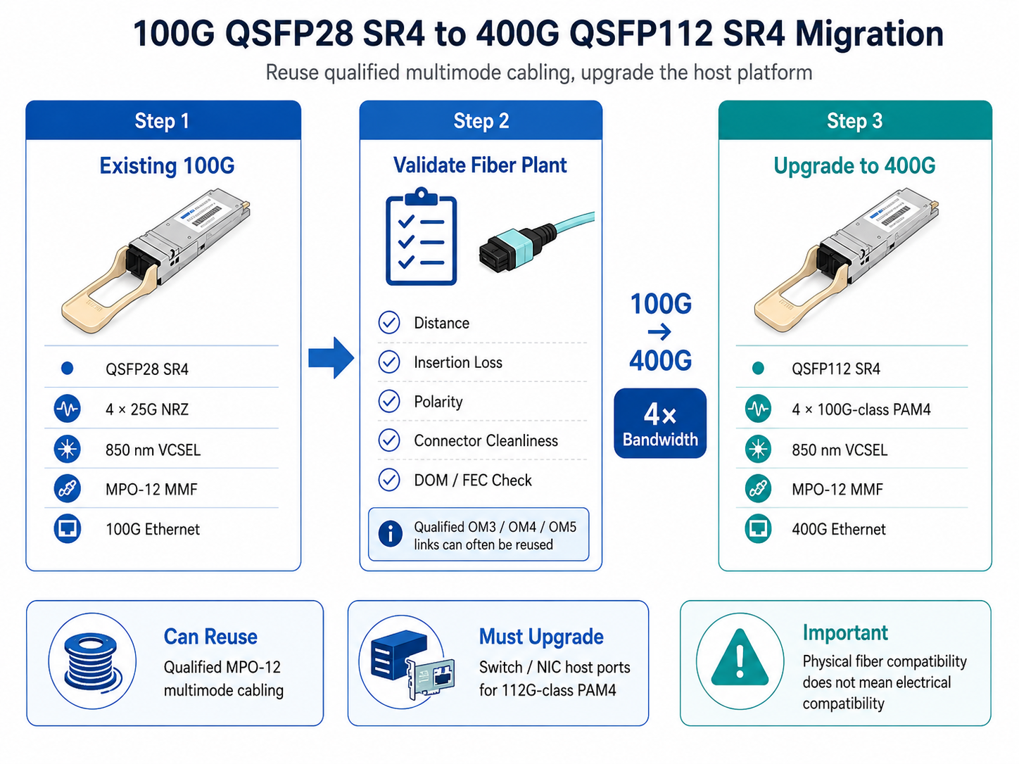
Migration from 100G QSFP28 SR4
Upgrading from 100G to 400G is a major infrastructure project. QSFP112 SR4 simplifies one part of that project by reusing existing multimode fiber. The MPO-12 connectors that served QSFP28 SR4 will serve QSFP112 SR4 on the same OM4 cables.
However, migration requires careful sequencing. First, upgrade the switches. New leaf and spine switches must have QSFP112 ports with 112 Gbps PAM4 ASICs. QSFP112 SR4 modules will not function in legacy QSFP28 ports, even though the fiber fits.
Second, validate the fiber plant. Test every link for distance, loss, and connector quality. Links that worked reliably at 100G may have intermittent issues at 400G due to higher sensitivity to reflections and loss.
Third, deploy modules incrementally. Start with a pilot rack. Verify link stability under production traffic. Monitor DOM readings for several days before expanding to the full row. This measured approach catches fiber plant issues early, before they affect critical workloads.
Installation, Polarity, and Maintenance Best Practices
MPO-12 Polarity Types for 400G
Polarity defines how transmit fibers at one end map to the receive fibers at the other. For QSFP112 SR4, correct polarity ensures that each of the four transmit lanes connects to the corresponding receive lane.
Method A uses straight-through mapping. Position 1 connects to position 1, position 2 to position 2, and so on. This method requires a special A-to-B patch cord at one end to flip transmit and receive channels.
Method B reverses the fiber order at one end. Position 1 connects to position 12, position 2 to position 11. This reversal achieves the required transmit-to-receive mapping without special patch cords. Method B is the most common polarity scheme in data center trunk cabling.
Method C pairs fibers in crossover groups. It is rarely used in modern 400G deployments. When installing new cabling, standardize on Method B for simplicity. When integrating with an existing plant, document the existing polarity method and ensure all new components match.
Connector Cleaning and Inspection
Connector cleanliness directly impacts 400G link performance. At 850nm and 112 Gbps PAM4, even small contaminants cause significant signal degradation. A single dust particle can block a substantial portion of the optical signal.
Best practice is to inspect before connecting. Every MPO connector should be examined with a fiber inspection probe before mating. Look for dust, oil, scratches, and pitting. Reject any connector that does not meet cleanliness standards.
Cleaning requires proper technique. Use lint-free wipes and approved optical cleaning fluid. For MPO connectors, specialized cleaning tools that engage all twelve fibers simultaneously are more effective than single-fiber methods. After cleaning, inspect again to verify the result.
Establish a cleaning discipline in your data center. Require technicians to inspect and clean every connector during installation. Keep cleaning supplies readily available at patch panel locations. The five minutes spent cleaning a connector prevent hours of troubleshooting intermittent link failures later.
Pre-Deployment Validation
Validation before production deployment catches problems while they are still easy to fix. Three tests form the core of QSFP112 SR4 link validation.
Optical loss testing comes first. Use an optical loss test set to measure end-to-end insertion loss. Compare the result against the link budget for your fiber grade. If loss exceeds the budget, identify and repair the high-loss component before proceeding.
Digital optical monitoring baseline comes second. After installing the QSFP112 SR4 modules, record initial DOM readings for transmit power, receive power, temperature, and voltage on every lane. These baselines become your reference for future troubleshooting. A gradual decline in received power may indicate connector degradation or fiber microbending.
FEC error rate monitoring comes third. During burn-in testing, monitor the FEC symbol error rate on each lane. Error rates should stabilize near zero within minutes of link establishment. Persistently high error rates indicate marginal optical performance that will cause problems under heavy traffic loads.
A data center operations team in Sydney learned this lesson the hard way. They deployed 64 QSFP112 SR4 links without pre-deployment validation. Within 72 hours, 11 links showed intermittent failures. Root cause analysis revealed that five MPO connectors had polarity mismatches and six had excessive insertion loss due to dirty end-faces. A two-hour validation procedure would have prevented three days of troubleshooting.
Conclusion
QSFP112 SR4 optical transceiver modules offer a practical, cost-effective path to 400G for short-reach data center links. By leveraging existing OM4 and OM5 multimode fiber plants, network engineers can quadruple bandwidth without the expense of recabling. The key is matching the module to the application. Use QSFP112 SR4 for links under 100 meters where multimode fiber exists. Choose DR4 or FR4 when distances demand single-mode capabilities.
Successful deployment depends on attention to detail. Verify fiber distances and loss budgets. Confirm MPO polarity before installation. Inspect and clean every connector. Monitor DOM and FEC metrics during burn-in. These practices transform QSFP112 SR4 from a specification sheet into a reliable production network component.
Ready to upgrade your data center to 400G? AscentOptics provides QSFP112 optical transceiver modules engineered for stable performance in demanding network environments. Our engineers can help you assess your fiber plant, verify compatibility with your switch platforms, and design a migration path from 100G to 400G that minimizes risk and cost. Contact our optical networking experts today or explore our 400G QSFP112 SR4 solutions.
Post Views: 781