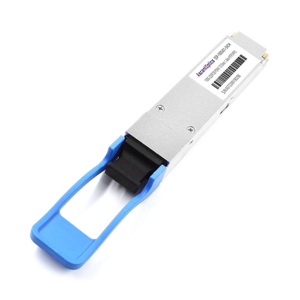
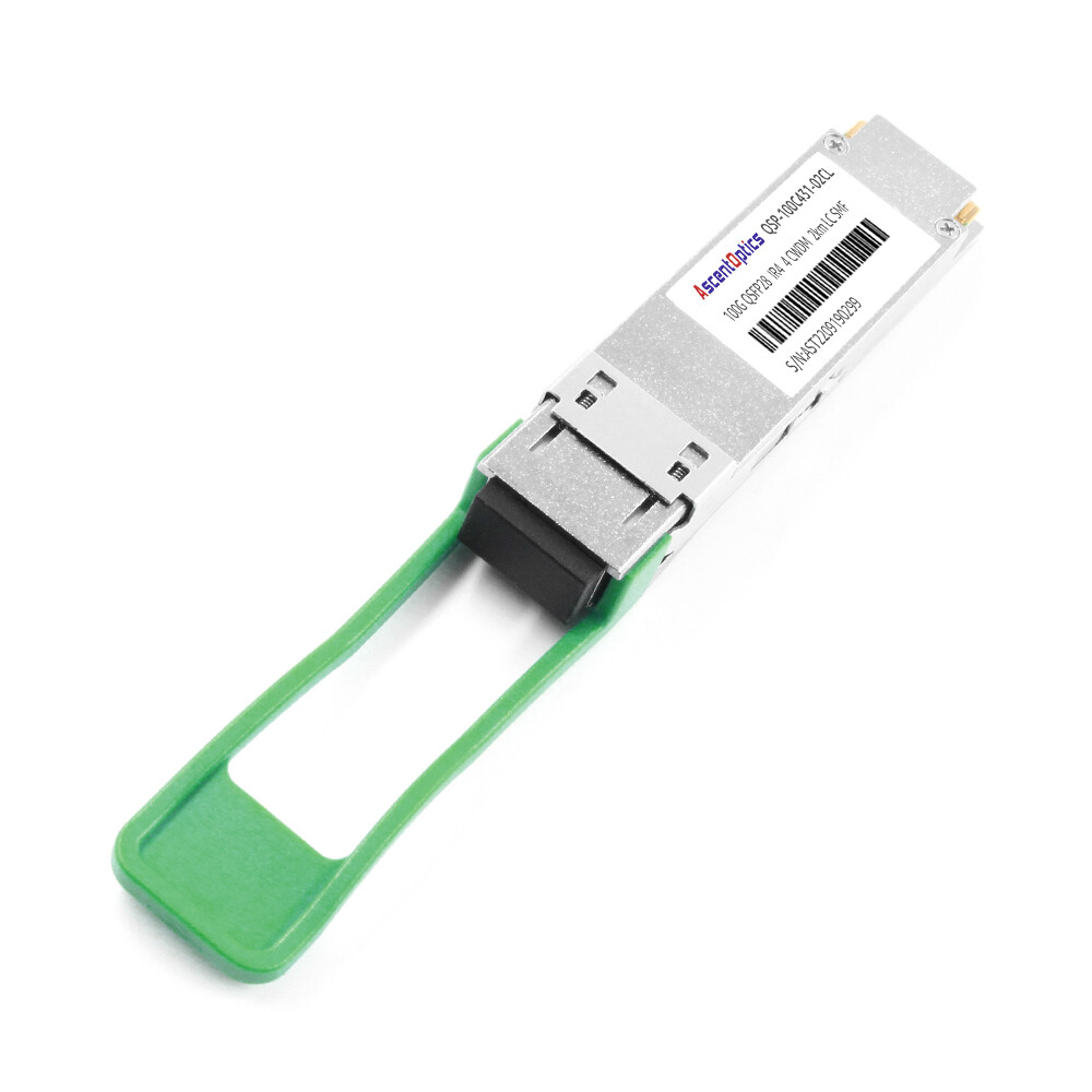
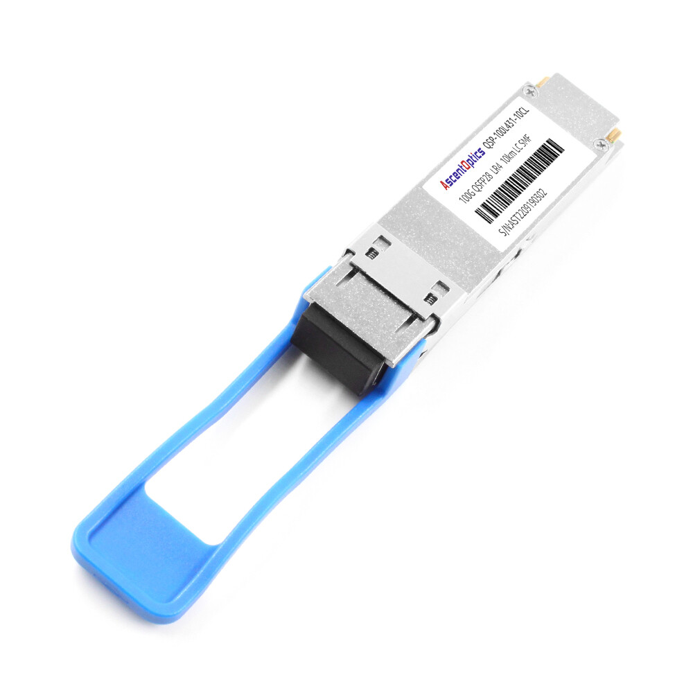
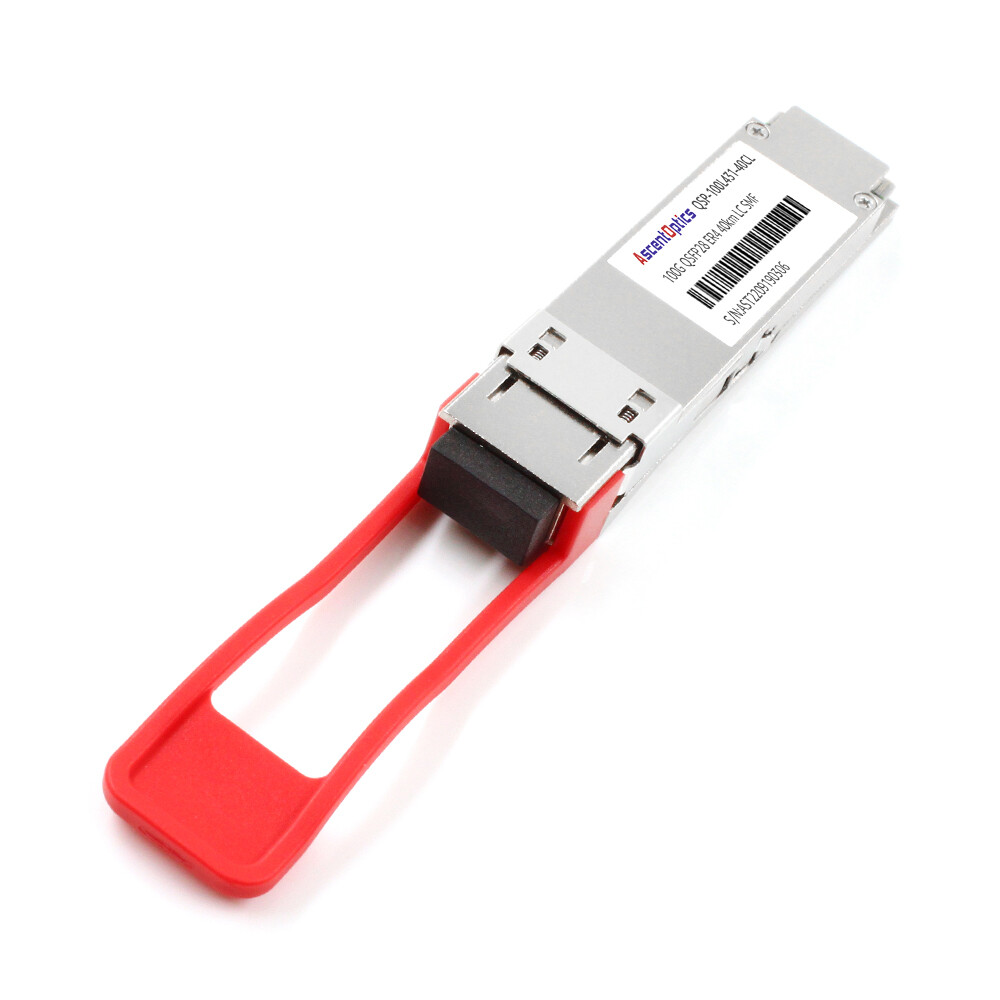
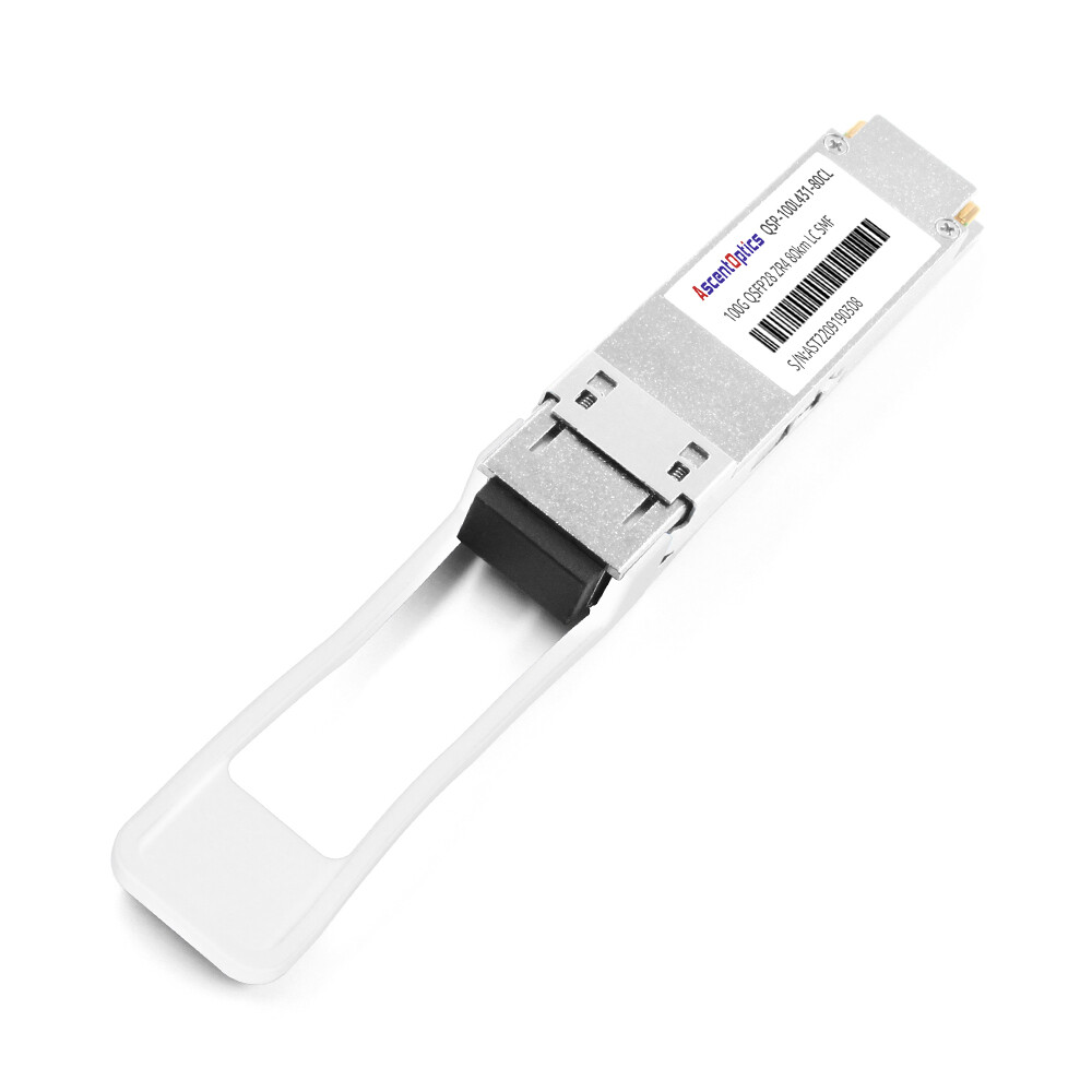
The QSFP56 standard architecture involves IEEE 802.3bs/cd, MSA, and CMIS, all of which specify the electrical interface, optical interface, and management interface of 200G/400G transceivers, respectively. They facilitate compatibility between various vendors’ products, provide flexibility in terms of growth in speed in Ethernet, and, via unified digital diagnostics through CMIS, offer a base for upgrading to high bandwidths.
What Is QSFP56?
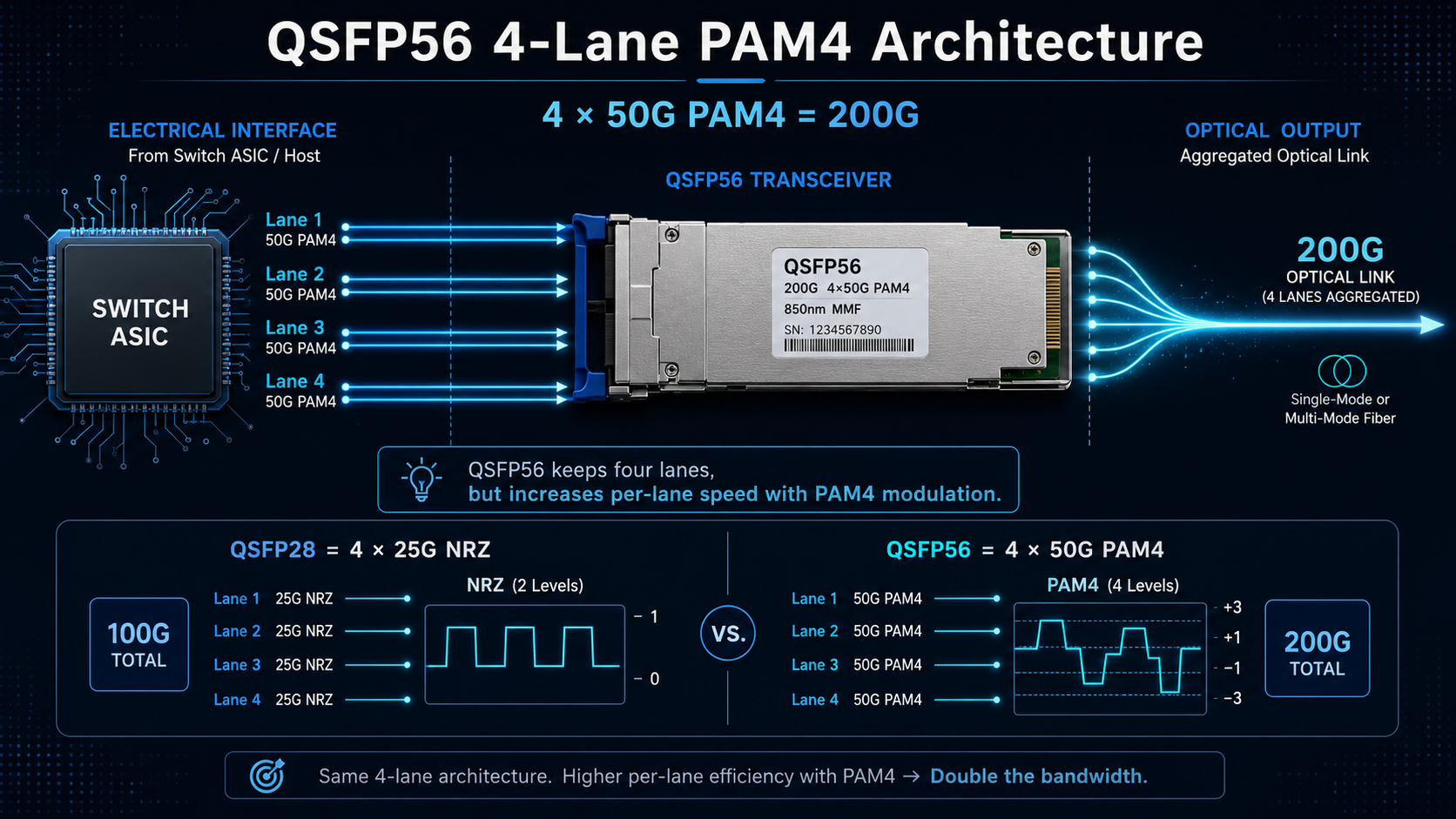
QSFP56 stands for Quad Small Form-Factor Pluggable 56. It is a hot-pluggable optical transceiver module that delivers 200 Gigabit Ethernet over four 50 Gbps lanes, using PAM4 modulation at 26.5625 GBd per lane. Each lane operates at approximately 53.125 Gb/s, including encoding overhead, providing an aggregate 200GbE interface.
The “56” in the name refers to the per-lane baud rate class. That single detail explains the entire generation jump from QSFP28. Where QSFP28 pushes four 25 Gbps lanes using simpler NRZ signaling, QSFP56 doubles the per-lane rate by moving to PAM4.
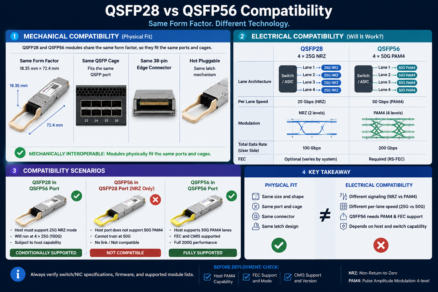
QSFP56 keeps the same mechanical form factor as QSFP28. Same 38-pin edge connector, same cage, same footprint. The difference lives entirely in the electrical and optical signaling, which is precisely why the standards matter so much.
The QSFP56 Standards Stack: How the Documents Fit Together
No single document defines a QSFP56 module. Instead, five layers of standards work together, each governing a different slice of the design. Thinking of them as a stack makes the whole system far easier to reason about.
QSFP56 MSA: The Mechanical and Functional Agreement
The QSFP56 Multi-Source Agreement is the foundation. It is an industry consortium agreement that fixes the mechanical dimensions, the connector pinout, and the thermal envelope so that a module from any compliant vendor physically fits and functions in any compliant port. The MSA also defines the single +3.3 V power supply and the power-class framework, which runs from about 3.3 W up to 7 W depending on reach.
SFF Specifications: The Detailed Blueprint
The Small Form Factor (SFF) committee documents turn the MSA into engineering detail. SFF-8665 covers the QSFP pluggable interface, while SFF-8679 defines the base electrical and photonic signaling requirements. The older SFF-8636 handled the management interface for earlier generations and still matters for understanding how diagnostics evolved.
IEEE 802.3: The Optical Physical Layer
The IEEE 802.3 Ethernet standards define the optical PMDs, the physical medium dependent sublayers that determine reach, fiber type, and wavelength. This is the layer that gives you names like 200GBASE-DR4 and 200GBASE-FR4. We break these down in the next section.
OIF CEI-56G-VSR-PAM4: The Electrical Interface
The Optical Internetworking Forum (OIF) defines OIF CEI-56G-VSR-PAM4, the chip-to-module electrical interface. It specifies how the switch ASIC talks to the module’s DSP over very short-reach channels at 56 Gbps PAM4. You rarely see it on a marketing datasheet, but it is what makes the electrical link between host and module interoperable.
CMIS 4.0: The Management Brain
Finally, the Common Management Interface Specification (CMIS) 4.0 standardizes how the host reads and controls the module. It governs digital optical monitoring, power-class negotiation, FEC configuration, and firmware updates.
Visual suggestion: A stacked diagram showing each layer, the document that governs it, and what it controls (MSA → SFF → IEEE → CEI → CMIS).
QSFP56 Standards at a Glance
The following table summarizes the major standards that make up the QSFP56 ecosystem and the role each one plays.
| Standard |
Organization |
Primary Role |
| IEEE 802.3bs |
IEEE |
Defines 200GBASE-DR4, FR4, LR4 Ethernet PMDs and 200GAUI-4 electrical interface |
| IEEE 802.3cd |
IEEE |
Defines 200GBASE-SR4 multimode Ethernet PMD |
| QSFP56 MSA |
QSFP MSA Group |
Specifies the mechanical form factor, connector, power classes, and module interoperability |
| CMIS |
OIF |
Standardizes module management, diagnostics, and control over I²C |
| OIF CEI-56G |
OIF |
Defines the host electrical interface between the switch ASIC and the module |
| SFF Specifications |
SFF Committee |
Defines memory maps, hardware interface details, and legacy management specifications |
IEEE 802.3bs and 802.3cd: The 200G Optical PMDs
When engineers ask “which standard defines my module,” they usually mean the IEEE PMD. Two documents split the 200G QSFP56 family between them, and knowing the split saves real time during procurement.
IEEE 802.3bs-2017 is the workhorse. It defines the 200GAUI-4 electrical interface and three optical reaches:
- 200GBASE-DR4: 500 m over parallel single-mode fiber, MPO-12 connector
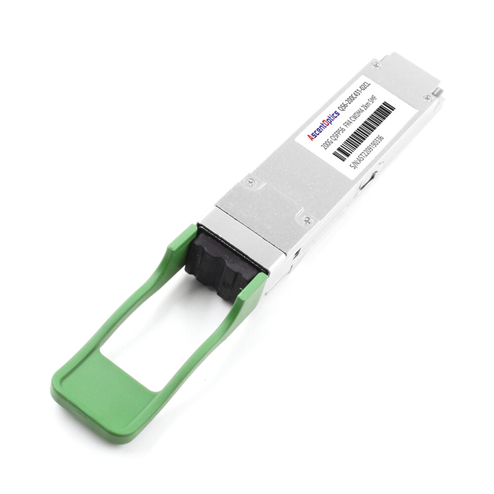
- 200GBASE-FR4: 2 km over duplex single-mode fiber using CWDM wavelengths (1271, 1291, 1311, 1331 nm), LC connector
- 200GBASE-LR4: 10 km over single-mode fiber, LC connector
IEEE 802.3cd-2018 arrived a year later and added the multimode option:
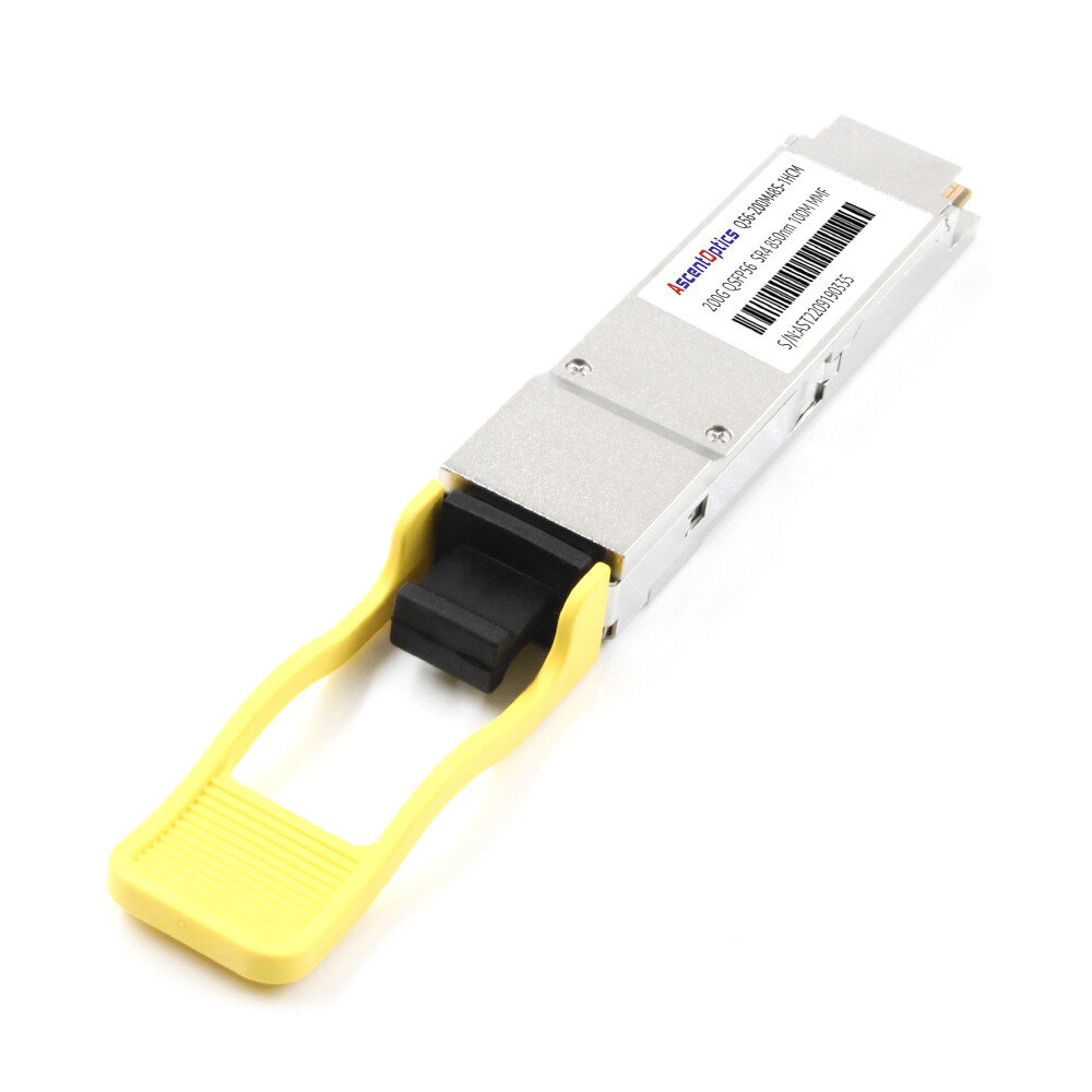
- 200GBASE-SR4: 70 m over OM3 or 100 m over OM4/OM5 multimode fiber, MPO-12 connector
IEEE 802.3cd complements IEEE 802.3bs by defining short-reach multimode PMDs such as 200GBASE-SR4.
| PMD |
IEEE Standard |
Fiber |
Connector |
Max Reach |
Typical Power |
| SR4 |
802.3cd |
Multimode (OM4) |
MPO-12 |
100 m |
~4-5 W |
| DR4 |
802.3bs |
Single-mode |
MPO-12 |
500 m |
~4-6 W |
| FR4 |
802.3bs |
Single-mode (CWDM) |
LC |
2 km |
~5-7 W |
| LR4 |
802.3bs |
Single-mode |
LC |
10 km |
~6-7.5 W |
Why PAM4 Makes FEC Mandatory
The move from NRZ to PAM4 is the single most important electrical change in QSFP56, and it carries a cost that the standards have to answer for.
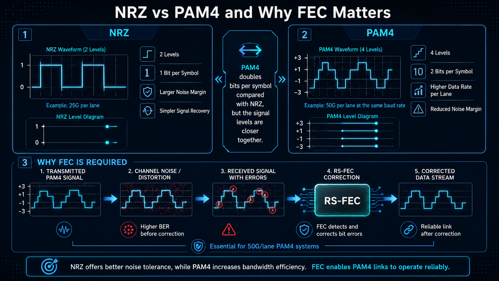
NRZ signaling uses two levels to encode one bit per symbol. PAM4 uses four levels to encode two bits per symbol, which doubles the data rate on the same baud rate. The trade-off is signal integrity. Squeezing four levels into the same voltage swing cuts the signal-to-noise margin by roughly 9 dB. At 50 Gbps per lane, that margin is too thin to run reliably on its own.
Most 200GbE QSFP56 links use RS(544,514) Reed-Solomon FEC defined by IEEE to achieve the required bit error rate.
QSFP56 MSA and SFF: Mechanical & Electrical Interoperability
Back at the form-factor layer, the QSFP56 MSA and the SFF documents are what guarantee that a module physically and electrically works across vendors. They fix the dimensions, the pinout, the thermal envelope, and the electrical signaling baseline.
This is also where the most persistent compatibility myth lives. Because QSFP56 is mechanically identical to QSFP28, many people assume the two are electrically interchangeable. They are not. QSFP28 runs NRZ, while QSFP56 runs PAM4. A QSFP56 module will not fall back to 100G in a port that only understands QSFP28 NRZ signaling.
The reverse is more forgiving. A QSFP28 module will often run at 100G in a QSFP56-capable port because the host hardware can negotiate down to NRZ. But this depends entirely on the switch and its firmware, so you must verify host support rather than assume it.
CMIS 4.0: Management, DOM, and Power Classes
CMIS 4.0 is the standard that ties monitoring and control together, and it matters far more at 200G than it did at earlier speeds.
CMIS replaced and extended the older SFF-8636 management approach. Over a standard I2C interface, it gives the host a rich, real-time view into the module: temperature, supply voltage, transmit and receive optical power, and laser bias current. It also standardizes power-class negotiation, FEC configuration, alarm thresholds, and even firmware updates.
For a single link, this is convenient. For a data center running thousands of 200G modules, it is essential. Standardized digital optical monitoring means your network management system can poll every module the same way, regardless of vendor, and catch a degrading laser before it takes down a spine link.
The catch is that CMIS support must be present on both ends. A module that fully implements CMIS 4.0 still needs a host that reads it. When you qualify optics, confirming CMIS 4.0 compliance on the module and CMIS awareness on the switch is what turns raw telemetry into actionable monitoring. In addition to digital diagnostics, CMIS defines standardized module state machines, firmware management, and advanced control functions that simplify large-scale network operations.
Conclusion
QSFP56 standards are not defined by a single specification but by a complete ecosystem of IEEE, MSA, CMIS, OIF, and SFF documents. Together, these standards ensure interoperability, simplify deployment, and provide the foundation for reliable 200G Ethernet networks. Understanding how these specifications work together helps engineers select compatible modules, troubleshoot interoperability issues, and build scalable high-speed infrastructures.
Frequently Asked Questions
Which IEEE standard defines 200GBASE-DR4?
IEEE 802.3bs-2017 defines 200GBASE-DR4, along with 200GBASE-FR4 and 200GBASE-LR4. DR4 runs 500 m over parallel single-mode fiber using an MPO-12 connector.
Which IEEE standard defines 200GBASE-SR4?
IEEE 802.3cd-2018 defines 200GBASE-SR4, the multimode variant. It reaches 70 m over OM3 and 100 m over OM4 or OM5 fiber.
What is the QSFP56 MSA?
The QSFP56 MSA is a multi-source agreement that fixes the module’s mechanical dimensions, connector pinout, power supply, and thermal envelope. It guarantees that compliant modules physically fit and function in compliant ports across vendors.
What is CMIS 4.0 in 200G transceivers?
CMIS 4.0 is the Common Management Interface Specification. It standardizes digital optical monitoring, power-class negotiation, FEC configuration, and firmware updates over an I2C interface, giving hosts a consistent way to read and control modules.
Is QSFP56 backward compatible with QSFP28?
Not electrically. QSFP56 uses PAM4 while QSFP28 uses NRZ, so a QSFP56 module will not run at 100G in a QSFP28-only port. A QSFP28 module may run in a QSFP56-capable port at 100G, but only if the host supports it.
Why does QSFP56 require FEC?
PAM4 signaling cuts the signal-to-noise margin by about 9 dB compared to NRZ. RS(544,514) forward error correction is required to keep the bit error rate within a reliable range at 50 Gbps per lane.
Post Views: 1,024