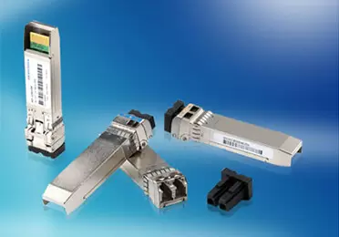
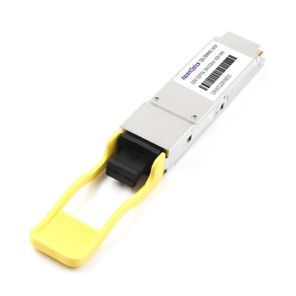
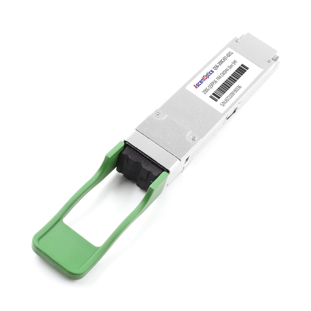
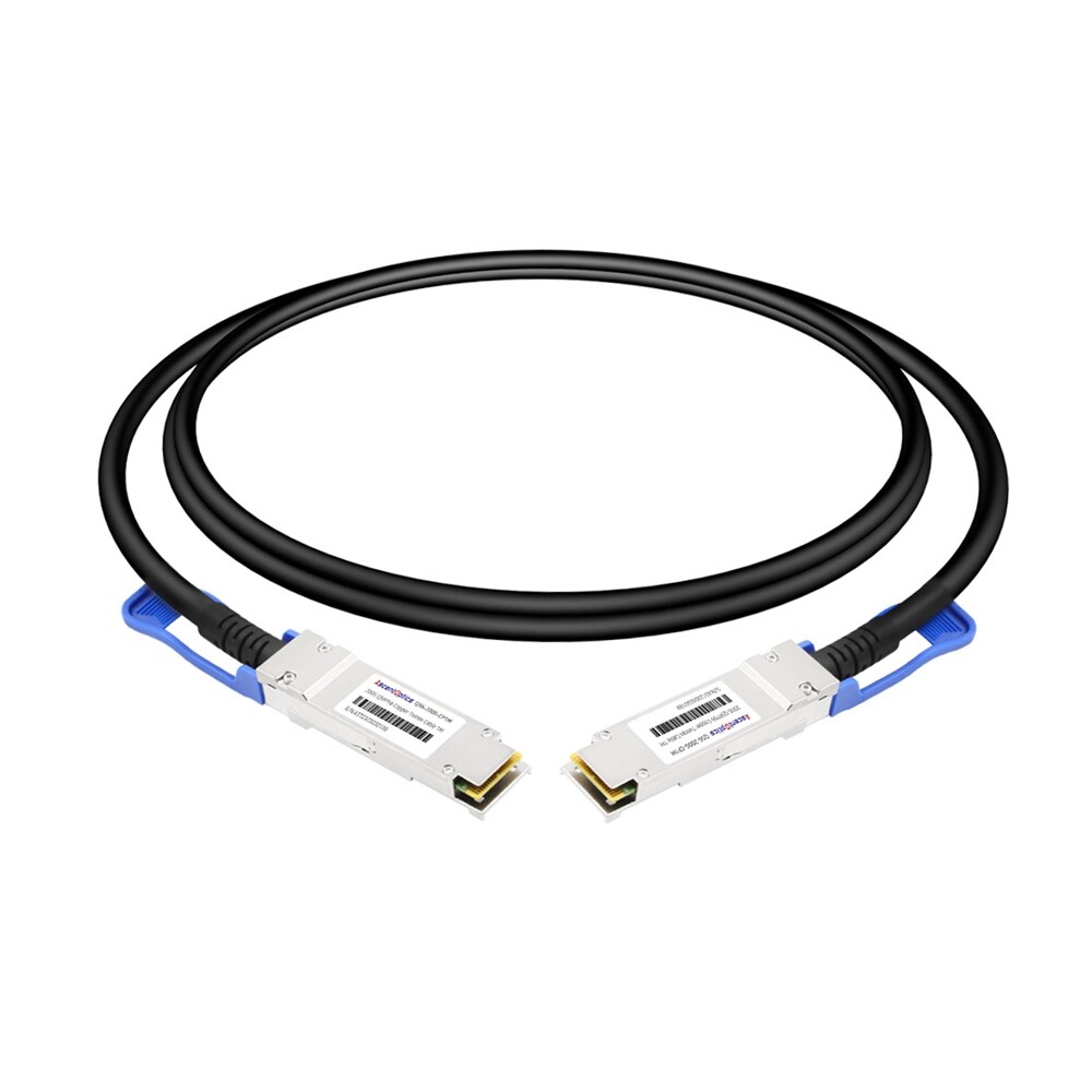
The LED is green. The interface shows up/up. Yet traffic is corrupt, pings drop, and your 200G link is effectively useless. If you have spent more than ten minutes troubleshooting a QSFP56 connection, you already know the hardest lesson: a green light does not mean a healthy link.
QSFP56 troubleshooting is fundamentally different from working with QSFP28. The move from NRZ to PAM4 signaling, the mandatory use of forward error correction, and the tighter optical power budgets all mean that failures can hide behind normal-looking status LEDs. Network engineers need a systematic framework, not guesswork, to isolate problems quickly.
Why QSFP56 Troubleshooting Is Different From QSFP28
Before you open the toolbox, it helps to understand why QSFP56 links fail in ways that QSFP28 links rarely do. The root causes come down to three technical shifts.
NRZ vs PAM4: Tighter Noise Margins
QSFP28 uses NRZ signaling: two voltage levels, one bit per symbol. QSFP56 uses PAM4: four voltage levels, two bits per symbol. PAM4 doubles the bit rate at the same baud rate, but the SNR penalty is roughly 9–10 dB. That means a QSFP56 link can look electrically stable while running right at the edge of acceptable signal quality.
In practical terms, a dirty connector or a 1 dB excess insertion loss that would not bother a 100G QSFP28 link can produce CRC errors on a 200G QSFP56 link.
Mandatory FEC Hides and Reveals Problems
QSFP56 relies on IEEE 802.3bs RS-FEC (544,514), which can correct up to 15 symbols per codeword. The native pre-FEC bit error rate of ~2.4 × 10⁻⁴ would be unacceptable without FEC. With FEC, traffic passes—but only if both ends agree on the same FEC mode.
When FEC modes mismatch, you get the classic “link up, no traffic” symptom. When physical-layer quality degrades, you see corrected FEC codewords climb. When things get really bad, uncorrected codewords appear, and frames are lost.
Higher Power and Thermal Sensitivity
QSFP56 modules typically draw 4.5 W to 7.5 W. That is significantly more than QSFP28 modules, and it makes thermal management part of troubleshooting. A module that passes at room temperature(especially in high-density 32-port or 64-port switches) can flap or fail when installed in a hot rack with poor airflow.
The Five-Layer QSFP56 Diagnostic Framework
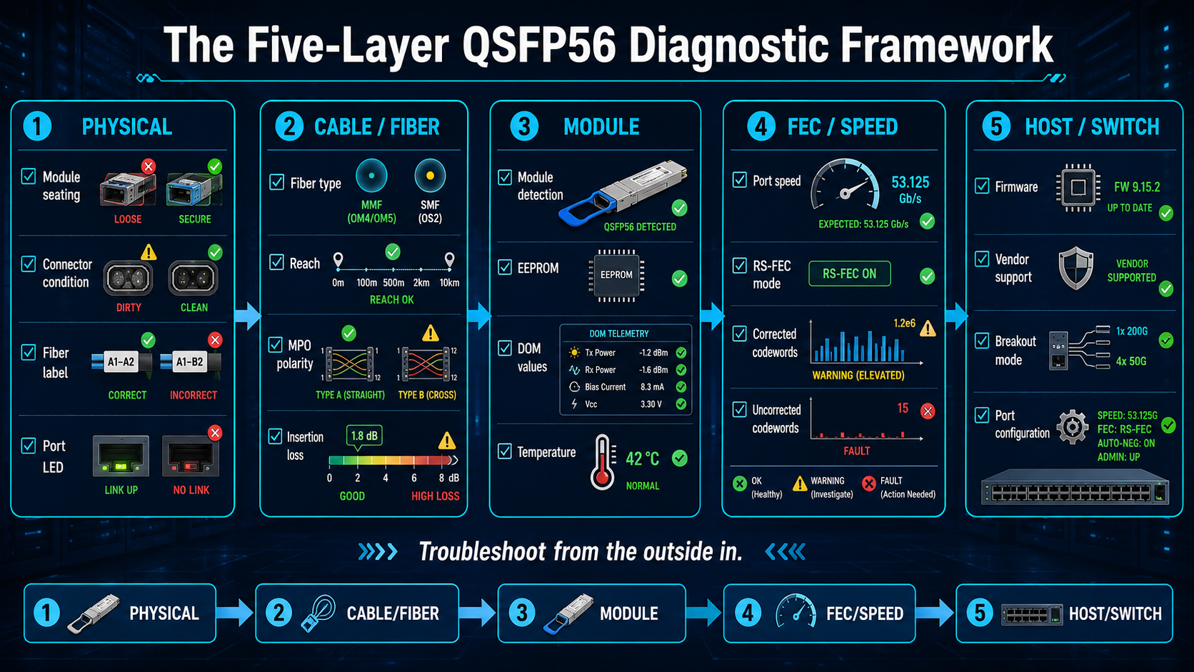
The fastest way to diagnose a QSFP56 issue is to isolate it in five layers. Move from the outside in: physical, cable, module, FEC, and host.
| Layer |
What to Check |
Common Failures |
| 1. Physical |
LEDs, connectors, module seating, labels |
Loose module, wrong fiber type, dirty endface |
| 2. Cable/Fiber |
Fiber type, reach, polarity, insertion loss |
MMF/SMF mismatch, MPO polarity error, loss budget exceeded |
| 3. Module |
Detection, DOM readings, EEPROM |
Unsupported transceiver, temperature alarm, RX power out of range |
| 4. FEC/Speed |
Port speed, FEC mode, error counters |
FEC mismatch, speed fallback, rising uncorrected codewords |
| 5. Host/Switch |
Firmware, platform support, breakout config |
Outdated firmware, unsupported breakout mode, vendor lock |
This framework prevents the most common troubleshooting mistake: replacing a module when the real problem is a configuration setting or a dirty connector.
Symptom 1: QSFP56 Link Down or Not Detected
A completely dead link is often the easiest symptom to diagnose because the failure is binary. Start with the basics and resist the urge to blame the module first.
Quick Triage Checklist
- Verify the module is fully seated in the cage. A partially seated QSFP56 can draw power but fail to establish lanes.
- Check the module label against the fiber cable. An SR4 module requires multimode fiber and an MPO connector; an FR4 or LR4 module requires single-mode fiber and LC duplex.
- Confirm the switch port is configured for 200G. Some platforms default to 100G when a QSFP28 module is inserted or when the speed is not explicitly set.
- Inspect the fiber endfaces with a 400× fiber microscope. Dust, oil, or scratches are the leading physical-layer cause of link-down conditions.
Common Causes
- •Unsupported transceiver: The switch rejects the module because the EEPROM vendor ID does not match its approved list.
- •Speed mismatch: A QSFP28 module is installed in a QSFP56 port, or the port speed is manually set to 100G.
- •Fiber mismatch: Single-mode fiber on a multimode module, or vice versa.
- •Reach exceeded: The link distance or insertion loss exceeds the module’s power budget.
- •MPO polarity error: Lane mapping is wrong on SR4 or DR4 modules.
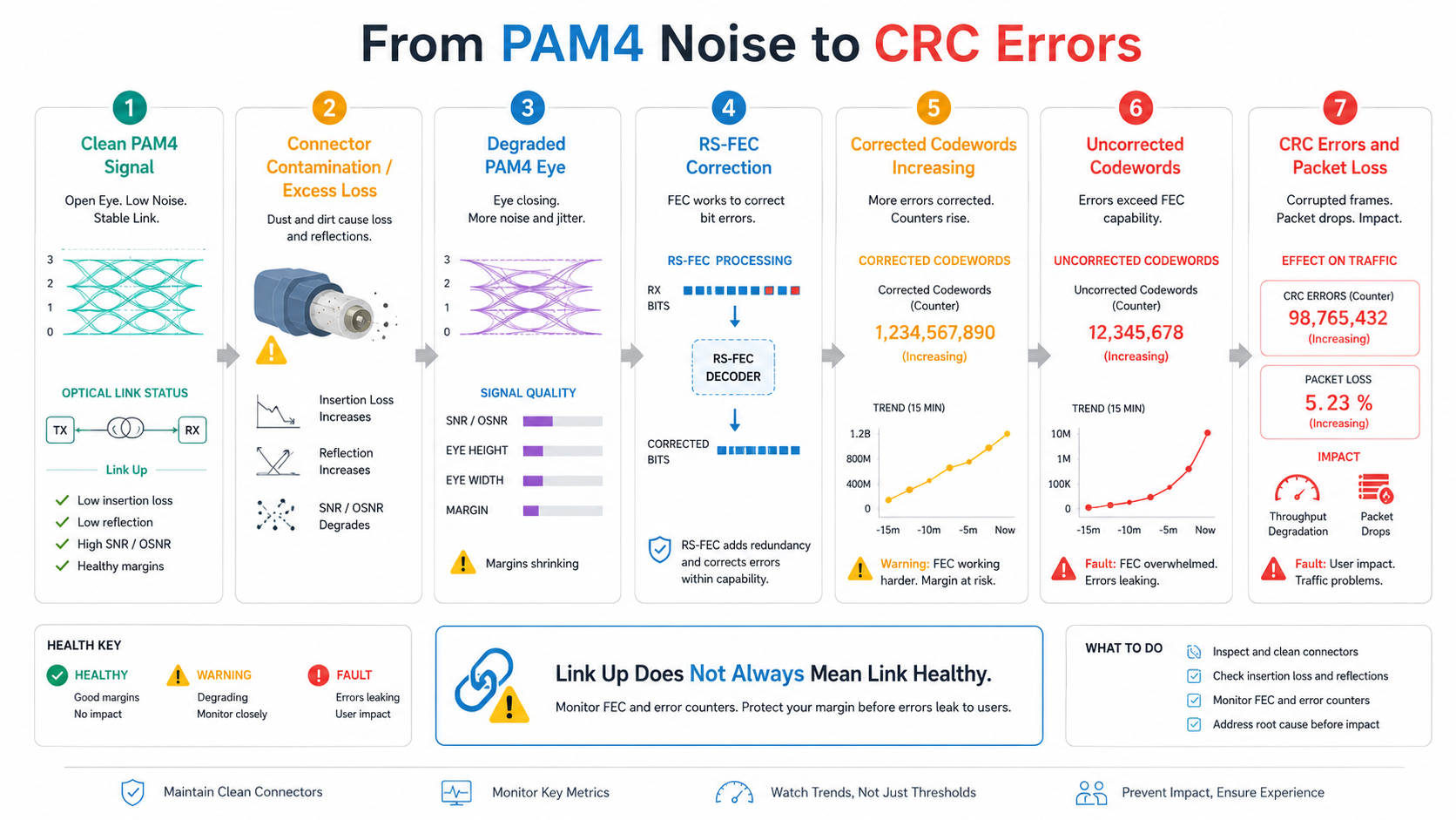
Symptom 2: Link is connected, but CRC errors or packet loss occur.
This is the signature QSFP56 failure. The link trains, the LED turns green, and the interface reportsup/up, yet CRC counters climb, and application traffic suffers.
Why PAM4 Links Show CRCs With a Green LED
Because PAM4 has a smaller eye opening, marginal signal quality can still be good enough for the PHY to declare link-up but bad enough that the FEC cannot correct every codeword. The result is intermittent CRC errors that do not trigger a full link-down event.
Connector Contamination and Insertion Loss
Start with the most likely culprit: the fiber. Clean both endfaces with a dry cleaning tool or lint-free wipe and inspect again. Even a tiny speck of dust can cause enough reflection and loss to corrupt a PAM4 signal.
Next, measure end-to-end insertion loss with an optical light source and power meter, or an OLTS. Compare the result against the module’s loss budget. For short-reach SR4 modules, the total channel loss is typically tight; any extra patch panel or dirty adapter can push the link over the edge.
Symptom 3: FEC Alignment Failures
Few things are more frustrating than a link that is administratively up but passes no usable traffic. On QSFP56, this is often an FEC mismatch.
Why FEC Is Mandatory for QSFP56
QSFP56 uses PAM4 signaling at 53.125 GBd per lane. The raw bit error rate is too high for reliable Ethernet without FEC. IEEE 802.3bs specifies RS-FEC (544,514) for 200GbE. Both ends of the link must use the same FEC mode, and in most cases, you should lock it manually rather than rely on auto-negotiation.
Symptom 4: DOM/Diagnostics Alarms
Digital Optical Monitoring (DOM), also called Digital Diagnostics Monitoring (DDM), gives you real-time telemetry from the module. Learning to read these values is essential for QSFP56 troubleshooting.
Standard DOM Parameters and Normal Thresholds
| Parameter |
Typical Normal Range |
Notes |
| Temperature |
0°C to 70°C (commercial) |
Hotter modules drift and flap |
| Voltage |
3.13 V to 3.47 V |
Outside ±5% triggers alarm |
| TX Power (SR4) |
-4.2 to +4.7 dBm |
Low TX can indicate laser aging |
| RX Power (SR4) |
-8.4 to +4.0 dBm |
Below sensitivity causes errors |
| Bias Current |
Vendor-specific |
Sudden changes suggest laser instability |
Always compare the suspect port against a healthy port on the same switch. A single value slightly out of range is more meaningful when neighboring ports look different.
Temperature, Voltage, and RX Power Alarms
- •High temperature: Check rack airflow, blanking panels, and adjacent high-power modules. Thermal shutdown often happens above 70°C.
- •Voltage alarm: Verify the switch power supply and seating. A loose module can show voltage spikes.
- •Low RX power: Clean connectors, measure insertion loss, and confirm the link distance is within budget.
DOM values should be evaluated as a trend rather than as isolated measurements. Gradual changes in RX power, bias current, or temperature over time often provide earlier warning of fiber contamination or laser degradation than a single snapshot.
Symptom 5: Module not recognized
When a switch refuses to recognize a QSFP56 module, the issue is usually vendor lock, firmware, or EEPROM coding—not a defective module.
Vendor Lock and EEPROM Coding Issues
Major switch vendors maintain approved vendor lists in their firmware. A third-party MSA-compatible module may work perfectly but be rejected because its EEPROM reports a generic or unrecognized vendor ID. This is especially common when mixing optics from different suppliers in the same chassis.
When to Request Custom Coding
If you are deploying third-party modules at scale and cannot enable unsupported-transceiver mode on every switch, the cleanest fix is custom EEPROM coding. Ascent Optics provides OEM/ODM services that program modules with the exact vendor ID and compatibility profile your switches expect. This avoids recognition errors without sacrificing supply-chain flexibility.
Symptom 6: Intermittent Link Flaps
Intermittent flaps are the hardest symptom to diagnose because the link works—until it does not. The root cause is usually thermal, mechanical, or optical marginality.
Thermal Stress and Airflow
QSFP56 modules run hot. If a link flaps only under load or only during peak data center temperatures, suspect thermal stress. Check:
- •Ambient rack temperature
- •Airflow direction and blanking panels
- •Module temperature via DOM
- •Whether adjacent ports are populated with high-power optics
Improving airflow often fixes flapping more reliably than replacing the module.
MPO/MTP Polarity Errors
For SR4 and DR4 modules, MPO polarity determines which electrical lane maps to which optical fiber. A method: A cable in a Method B plant can cause lane misalignment, training failures, or stable links with high CRC rates.
Verify polarity with a polarity tester or by tracing the cable plant documentation. The three common methods are:
- •Method A: Straight-through key-up to key-down
- •Method B: Crossed key-up to key-up
- •Method C: Paired crossover
Always verify the polarity method used throughout the entire cabling channel rather than checking only a single patch cord.
Breakout Cable Lane Mapping Issues
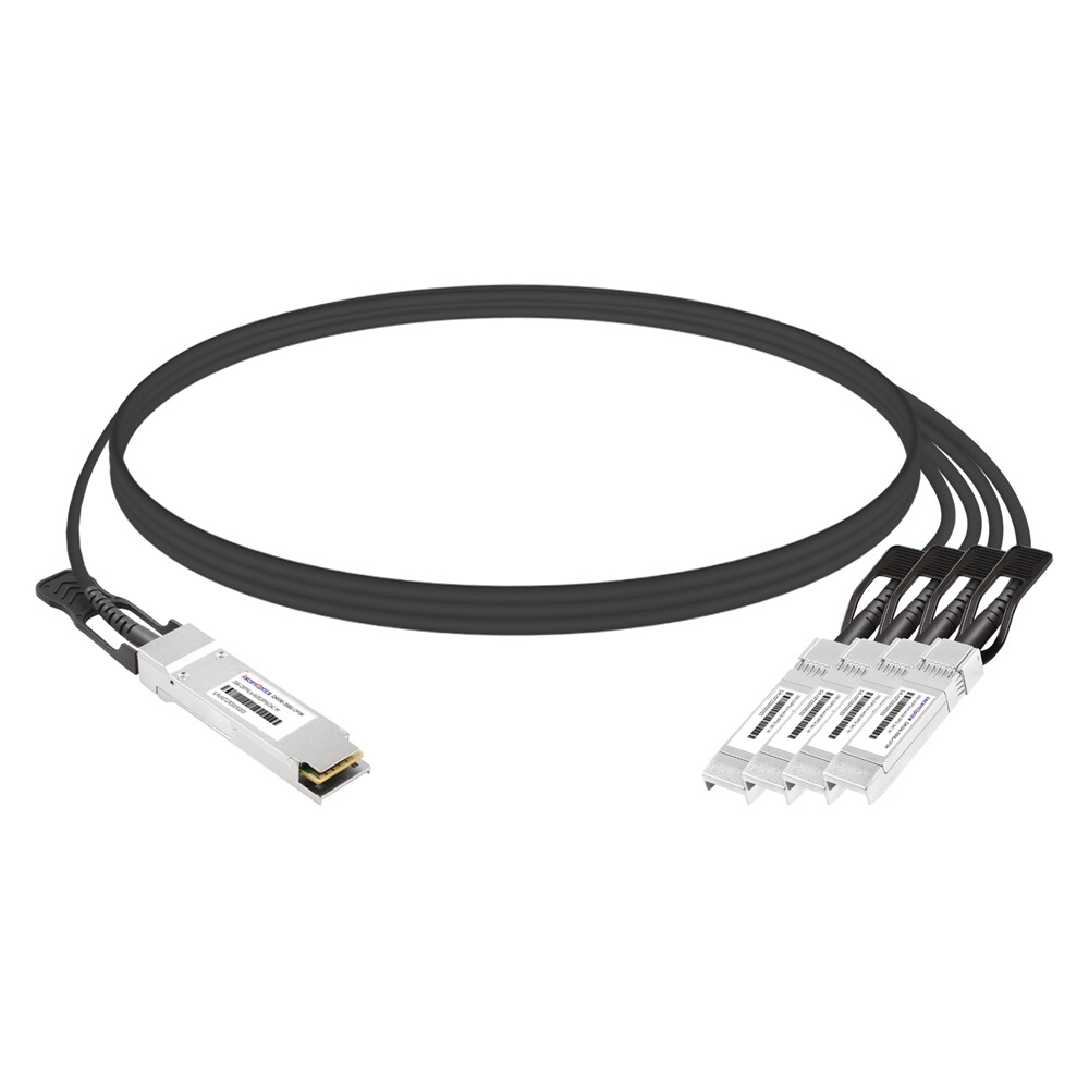
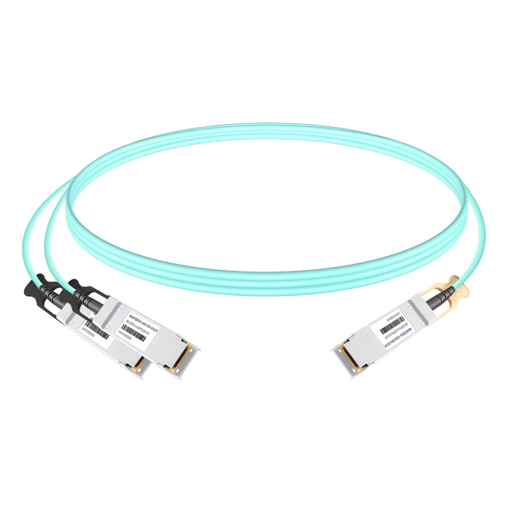
QSFP56 200G can break out to 2 × 100G QSFP28. Not every switch ASIC supports every breakout mode, and lane mapping must match the cable pinout. Check the switch datasheet before ordering breakout cables, and verify the breakout configuration in software.
Field-Proven QSFP56 Troubleshooting Workflow
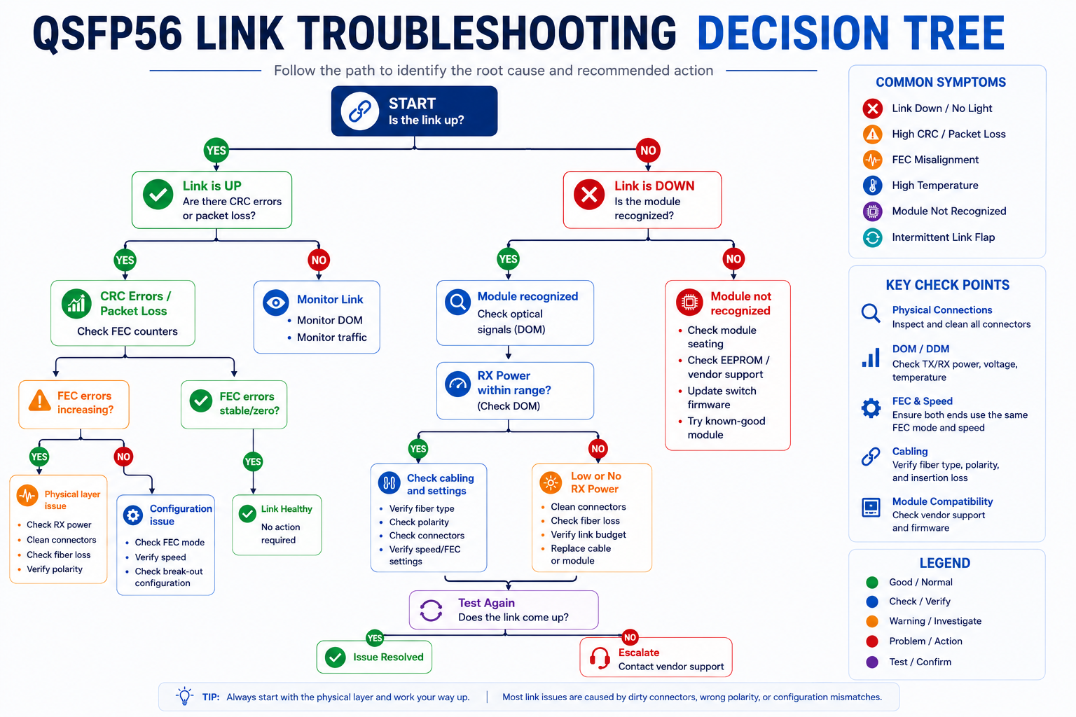
When you face a QSFP56 issue, follow this ordered workflow. It will save you from randomly swapping hardware.
Tools You Need
- •Fiber microscope (400×) and cleaning kit
- •Optical power meter / OLTS
- •OTDR for long or suspicious fiber runs
- •Known-good spare QSFP56 modules and cables
- •Loopback module for port self-test
- •Vendor CLI access to read DOM, FEC, and counters
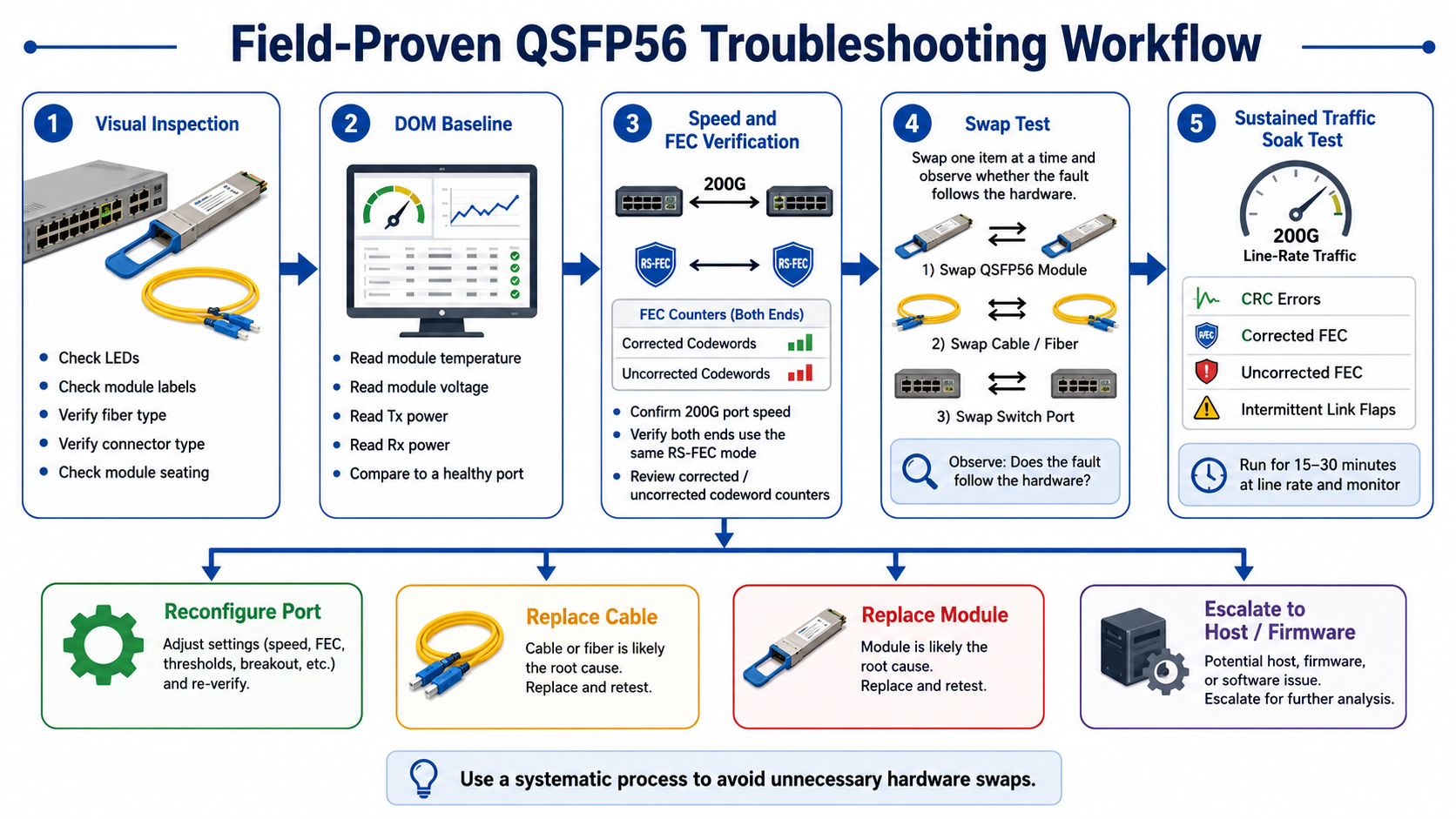
Step-by-Step Decision Tree
- 1. Visual inspection. Check LEDs, module labels, fiber type, connector type, and seating.
- 2. DOM baseline. Read temperature, voltage, TX/RX power, and compare to a healthy port.
- 3. FEC verification. Confirm both ends use the same RS-FEC mode and check corrected/uncorrected codewords.
- 4. Swap test. Move the suspect module to a known-good port; swap the cable; see if the issue follows the hardware.
- 5. Sustained traffic soak. Run line-rate traffic for 15–30 minutes. PAM4 links can pass light tests and fail under load.
When to Replace the Module vs. Reconfigure the Port
Replace the module when:
- •DOM shows out-of-spec TX power or temperature
- •The issue follows the module across multiple ports
- •Cleaning and reseating do not help
Reconfigure the port when:
- •FEC modes mismatch
- •Port speed is wrong
- •Vendor lock prevents recognition
- •Breakout mode is not supported
Preventing QSFP56 Issues: Best Practices
The best troubleshooting is the kind you do not have to do. A few disciplined habits will prevent most QSFP56 problems.
Connector Cleaning and Inspection
Always inspect and clean fiber endfaces before installing a module. Use a 400× microscope and dry cleaning tools. Never assume a new cable is clean; packaging debris is common.
Loss Budget Planning
Calculate the total channel loss before deployment. Include fiber attenuation, patch panels, adapters, and aging margin. For QSFP56 SR4, stay well below the maximum specified insertion loss.
Firmware and FEC Standardization
Keep switch firmware current and standardize FEC settings across your fabric. Lock RS-FEC manually on production 200G links rather than relying on auto-negotiation.
Spare Module Strategy
Keep known-good spare modules and cables on hand for isolation testing. A swap test is the fastest way to determine whether the fault is in the module, the cable, or the switch port.
Conclusion
QSFP56 troubleshooting rewards a systematic approach. The move to PAM4 and mandatory FEC means that green LEDs and up/up interfaces can hide real problems. By working through the five-layer framework—physical, cable, module, FEC, and host—you can isolate failures faster and avoid unnecessary hardware swaps.
As QSFP56 becomes a mainstream interface for 200G Ethernet, troubleshooting requires more than checking LEDs or swapping modules. Understanding PAM4 signaling, FEC behavior, DOM diagnostics, and optical loss budgets enables engineers to identify root causes quickly, minimize downtime, and maintain reliable high-speed network performance.
Frequently Asked Questions
Can a QSFP56 module pass traffic with CRC errors?
Yes. A QSFP56 link may remain operational while CRC errors increase because PAM4 signaling and FEC can mask marginal physical-layer conditions until the error rate exceeds the correction capability.
Should I replace the module immediately after a DOM alarm?
Not necessarily. Many DOM alarms are caused by dirty connectors, excessive insertion loss, poor airflow, or configuration issues. Always verify optical power, temperature, and FEC counters before replacing the module.
Why is my QSFP56 link up but still showing CRC errors?
A QSFP56 link can remain operational even when the PAM4 signal quality is marginal. RS-FEC may correct most transmission errors, allowing the interface to stay up, while a smaller number of uncorrected errors appear as CRC errors or packet loss. Check corrected and uncorrected FEC counters, inspect and clean the fiber connectors, verify optical power levels, and measure channel insertion loss.
Does a green port LED mean the QSFP56 link is healthy?
No. A green LED generally confirms that the physical link has trained successfully, but it does not prove that the connection is error-free. A link may still experience rising corrected codewords, uncorrected FEC errors, CRC errors, packet loss, or intermittent flaps. Always review interface counters, FEC statistics, and DOM readings.
Is FEC required for QSFP56 200G links?
Yes, 200G QSFP56 Ethernet links based on 50G PAM4 lanes normally require RS-FEC. PAM4 provides higher data rates but has a smaller noise margin than NRZ. Both ends of the link must use compatible FEC settings. A mismatch may cause link failure, FEC alignment problems, or a link that appears up but cannot pass traffic correctly.
What do uncorrected FEC codewords mean?
Uncorrected codewords mean that the number or pattern of errors exceeded the correction capability of the FEC decoder. These errors can pass into the Ethernet layer and produce CRC errors, frame loss, packet drops, and application performance problems. Any persistent increase in uncorrected codewords should be investigated immediately.
What causes corrected FEC codewords to increase?
Corrected codewords indicate that RS-FEC is repairing transmission errors before they affect user traffic. A slowly increasing counter can be normal, depending on the platform and link design. A rapid or accelerating increase may indicate dirty connectors, excessive insertion loss, poor signal integrity, thermal stress, fiber damage, or a marginal optical power budget.
Post Views: 1,152