Jennifer Chen thought that upgrading from 40G to 100G would be a simple module swap. In February 2025, her team ordered 200 QSFP28 SR4 transceivers to replace their existing 40G QSFP+ optics. Halfway through the deployment, they discovered that 40% of the legacy plant was OM3. The 100G links that were supposed to cover 100 meters actually failed at 60 meters.
This assumption made a two-week upgrade become a six-week recabling of the data center plan. It demonstrated to her that 40G to 100G migration must involve more than faster optics; it is rather a cabling, power, and compatibility puzzle that must be solved right.
This guide will help you avoid such surprises by walking you through fiber infrastructure audits, choosing the right migration path, managing the QSFP+ to QSFP28 transition, and steering clear of common pitfalls.
Need help planning your migration? Explore Ascent Optics’ QSFP28 transceiver portfolio or contact our engineers for a free upgrade roadmap.
Why Migrate from 40G to 100G Now?
Bandwidth Demand and AI/ML Networking
Current data centers witness immense bandwidth requirements that cannot be met by 40G links. AI training clusters, high-performance computing fabrics, and distributed storage systems generate massive east-west traffic that easily saturates 40G spine links.
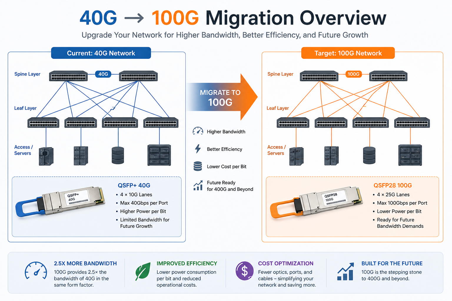
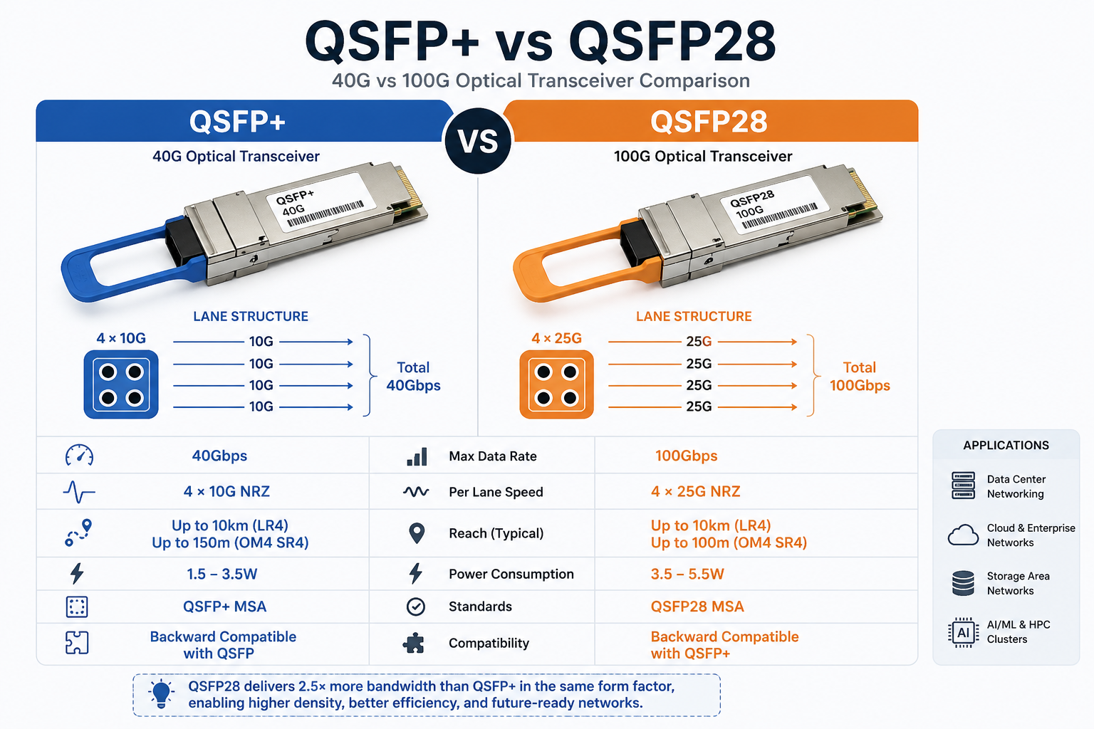
The 100G Ethernet provides 2.5 times the bandwidth of 40G within the same QSFP form factor. This density advantage allows more spine capacity within the same switch hardware infrastructure and without consuming more rack space.
Cost-per-Bit Efficiency
Though the price of a single QSFP28 module exceeds that of a QSFP+ module, the cost per gigabit is significantly lower. Running two 40G links to achieve 80G would require more power, more fiber, and more switch ports.
An organization moving groups of 40G duplex links to 100G links would typically experience a 30-50% reduction in power – per bit. The organizational topology would be simpler and they could manage fewer optics.
Future-Proofing for 400G and Beyond
QSFP28 ports provide a smooth evolutionary path toward 400G. While there are certain switches that can support hours with QSFP28 modules when placed on QSFP-DD ports supporting 400G as a standard, there are situations where 400G hardware would itself require QSFP28 symbiotics for testing; this and unrelated circumstances point to a paradigm shift under some current spots of which we will have to accept.
40G to 100G Migration Paths Compared
Not every data center needs the same upgrade strategy. The right path depends on your fiber plant, budget timeline, and risk tolerance.
Path 1: Direct Module Swap (Same Fiber)
The direct swap is the simplest and cheapest migration path. If your current fiber infrastructure supports 100G, you only need to replace the transceivers (and possibly switches) while keeping the existing cabling intact.
This path works perfectly for:
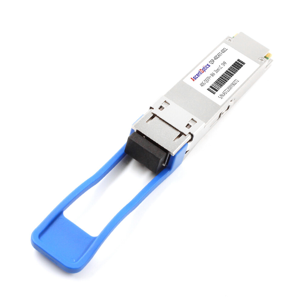
- •LR4 links over single-mode fiber: Both 40G LR4 and 100G LR4 use duplex LC single-mode fiber. Just swap the modules.
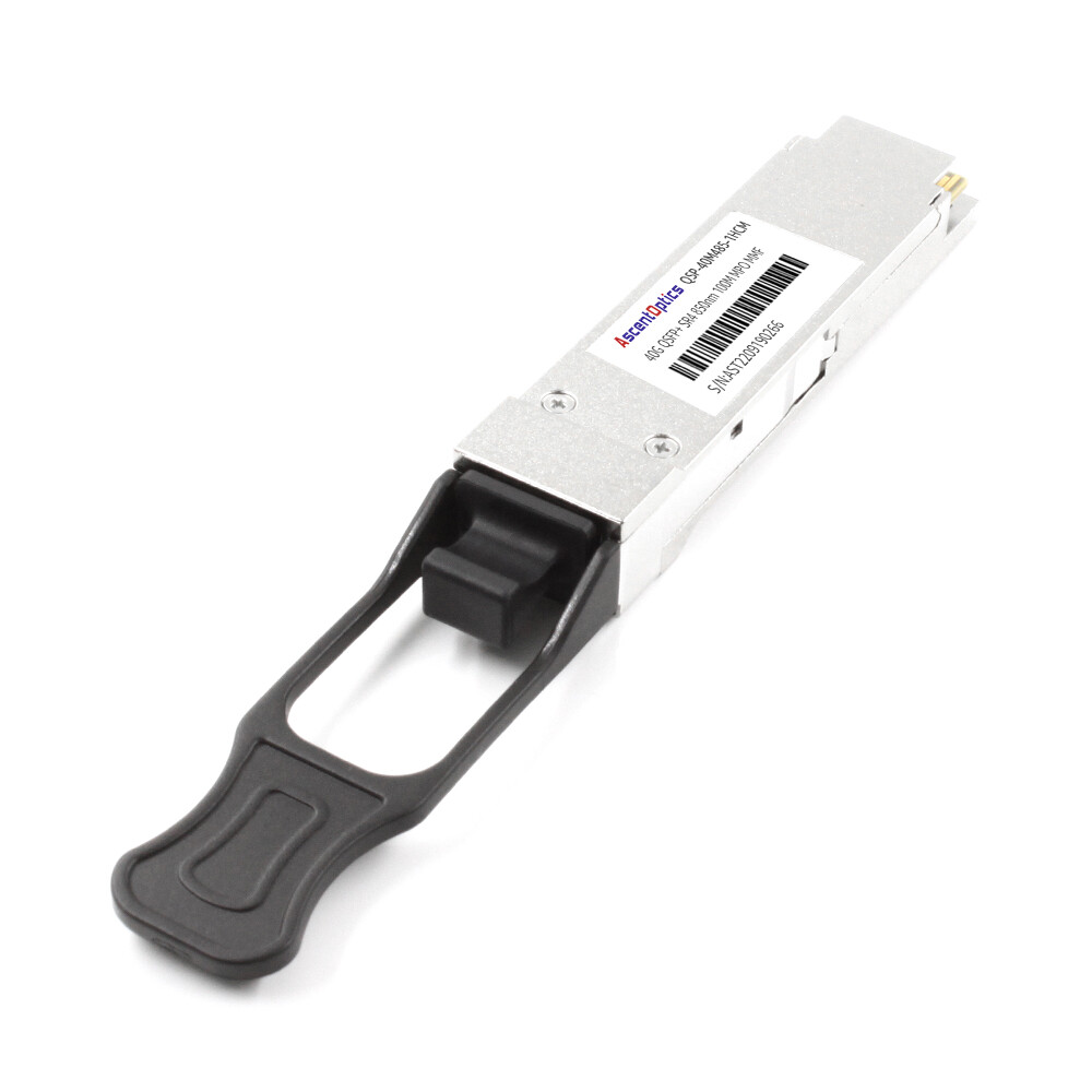
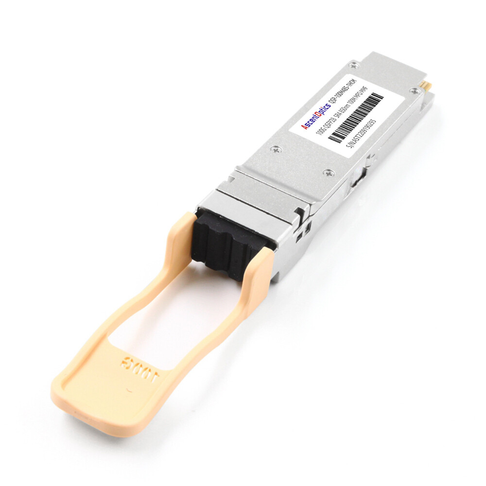
- •SR4 links over OM4 multimode fiber: Both 40G SR4 and 100G SR4 use MTP/MPO-12 connectors and OM4 fiber.
Path 2: Phased Hybrid Upgrade (Core First)
The phased approach is the most common strategy for enterprise data centers. You deploy 100G-capable switches at the core or spine layer first, then gradually upgrade the leaf and access layers over months or years.
This approach works because modern QSFP28 ports are backward compatible with QSFP+ modules. You can install a 100G switch and run your existing 40G optics in it until you are ready to buy 100G transceivers. For details on this compatibility, read our QSFP28 vs QSFP+ guide.
Path 3: Full Spine-Leaf Rebuild
While it can often turn out to be quite costly and invasive, performing a complete reset is usually performed for greenfield constructions or for outdated cabling plants situated in an existing data center. This option requires an all-at-once swap-out of switches, optics, and fiber infrastructure.
David Park operated a colocation facility on Singapore grounds; in 2024, his team had to double spine capacity without any additional racks. They came up with a staggered series of actions whereby they installed new QSFP28 spine switches as the first step and operated the existing 40G QSFP+ optics in the QSFP+ port of the QSFP28 switches. Then, over 18 months, they replaced optics module by module as leases renewed. Never had the facility gone down due to periodic maintenance outages. They spread the capital across four quarters and verified each link before moving traffic.
Migration Path Comparison
| Path |
Cost |
Downtime |
Risk |
Best For |
| Direct swap |
Lowest |
Minimal |
Low |
Same-fiber upgrades (LR4 SMF, SR4 OM4) |
| Phased hybrid |
Medium |
Low |
Low |
Most enterprises with mixed legacy gear |
| Full rebuild |
Highest |
Moderate |
Higher |
Greenfield builds or legacy plant replacement |
Not sure which path fits your network? Contact our optical networking experts for a customized migration assessment.
Cabling Infrastructure: The Foundation of Migration Success
When You Can Reuse Existing Fiber
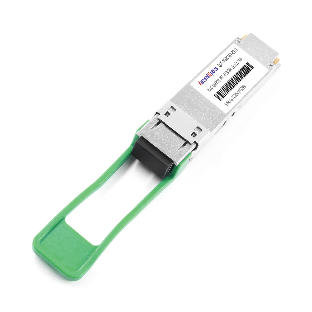
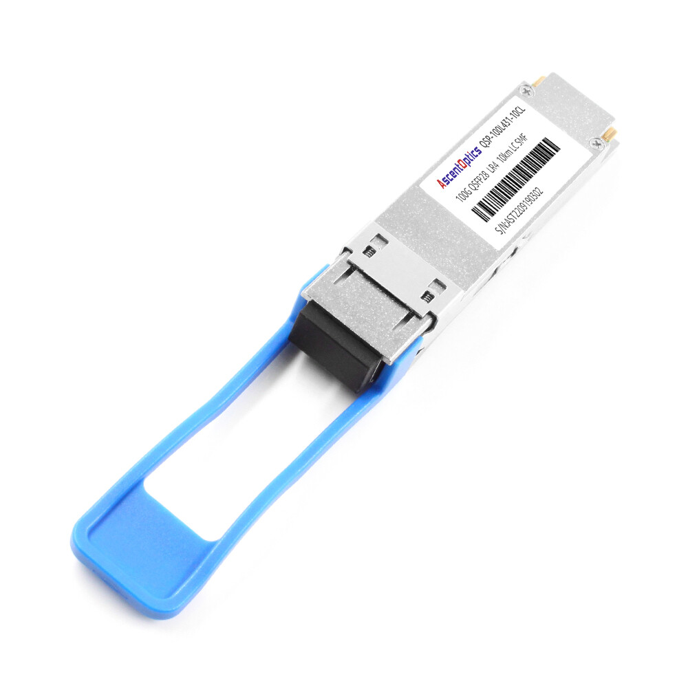
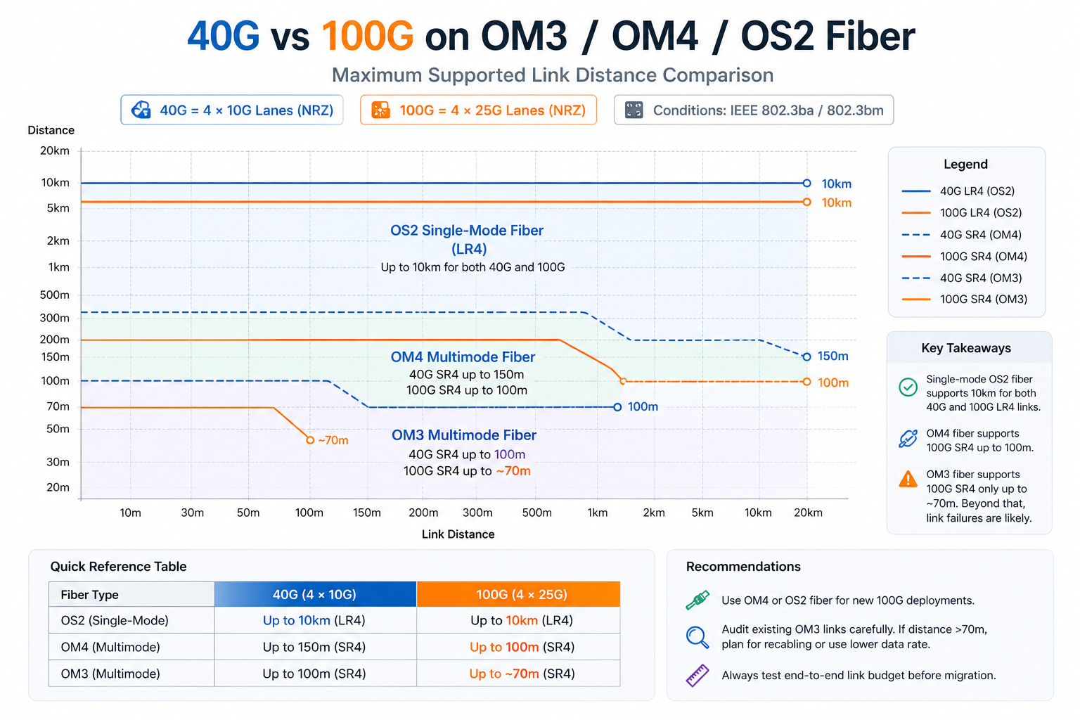
Single-mode fiber is the easiest to reuse. 40G LR4 and 100G LR4 both run over duplex LC OS2 fiber up to 10 km. 100G CWDM4 and ER4 also use the same fiber type.
For multimode fiber, the situation is more nuanced. OM4 supports both 40G SR4 and 100G SR4 up to 100 meters. However, OM3 supports 40G SR4 up to 100 meters but only supports 100G SR4 up to approximately 70 meters. Links approaching this limit on OM3 will likely require recabling for a successful 100G upgrade.
When You Need New Cabling
New cabling is typically required in these scenarios:
- 1. OM3 distance violations: Links longer than 70 meters require OM4 or single-mode for 100G SR4.
- 2. MTP to LC transitions: If you are moving from 40G SR4 (MTP) to 100G LR4 (LC duplex), the connector type changes.
- 3. Breakout architecture shifts: Moving from 4×10G SFP+ breakout to 4×25G SFP28 breakout may require new fan-out cables.
MTP/MPO vs. Duplex LC Decisions
Both 100G SR4 and 40G SR4 desire the MTP/MPO-12 connector. The 100G LR4 module, on the other hand, is a conventional duplex LC connector. The best migration path depends on the distance and fiber type -whether it uses an SR or LR?
For new builds in 2026, most architects recommend deploying OS2 single-mode fiber with LC connectors, as it supports LR4 today and offers the best path to 400G in the future.
12-Fiber vs. 24-Fiber vs. Base-8 Trunks
For MTP-based deployments, trunk selection affects your migration flexibility:
- •12-fiber trunks: Work well for 40G but can create stranded fibers when scaling to 100G and 400G.
- •24-fiber trunks: Support 100G natively and provide cleaner migration paths to 400G breakouts.
- •Base-8 trunks: Optimized for 100G/400G breakout with minimal fiber waste.
OM4 Multimode vs. OS2 Single-Mode for 100G
Its OM4 multimode is still the option for short data center links under 100 meters in size, but OS2 single-mode increasingly becomes the main choice on fresh builds because it supports all 100G module types and all future speeds.
Module Transition: From QSFP+ to QSFP28
SR4 Migration Over Multimode Fiber
QSFP+ SR4-type optical modules use four 10G lanes via OM3/OM4 optical fibers, while QSFP28 SR4 uses four 25G lanes via the same OM3/OM4 fibers but with zoning that has a tight reach. If your OM4 links are shorter than 100 meters, the migration would often be as simple as swapping out the module.
As Jennifer Chen’s team discovered, not all multimode fiber performs equally. Their facility had OM3 and OM4 mixed plant systems built during each of the construction phases. The 40G QSFP+ SR4 optics were doing fine on both because OM3 supports 40G to as far as 100 meters. But the 100G QSFP28 SR4 optics would drop the link after every OM3 run longer than 70 meters. The fix was replacing 80 MTP trunks with OM4; so, the module swap was 40k, together with an unanticipated 10k in recabling.
LR4 Migration Over Single-Mode Fiber
This is the cleanest migration path. Both 40G QSFP+ LR4 and 100G QSFP28 LR4 use duplex LC single-mode fiber and support up to 10 km. You replace the modules, verify FEC settings, and bring up the links. No cabling changes are required.
For a detailed module comparison, see our guide on 40G QSFP+ LR4 vs 100G QSFP28 LR4.
CWDM4 as the Cost-Optimized Middle Ground
QSFP28 CWDM4 supports 2 km over duplex LC single-mode fiber. CWDM4 is significantly cheaper than LR4 and somewhat costlier than SR4. Beyond the campus radius of 0.5 km and out to 2 km, CWDM4 has generally proven to be the most economical choice.
If you are currently running 40G LR4 for short links within the campus, think about spreading it with CWDM4, possibly at a cheaper rate.
Breakout Cable Migration (4×10G to 4×25G)
These days most data centers using QSFP+ fan-out cables to split 40Gb into four 10Gb server links. In upgrading to 100Gb, this fan-out architecture changes to QSFP28-to-4×SFP28 cables for four 25Gb links.
It is easy to ignore this change. QSFP+ breakout cables use 10G NRZ signaling. QSFP28 breakout cables use 25G NRZ signaling. Irrespective of the physical connectors being similar, the two are not cross-compatible.
In 2024, Michael Torres opted for 100G leaf switches with QSFP+-to-4×SFP+ breakout cables. Their connectors lined up beautifully — but the server NICs would not link. It took two days of troubleshooting to realize that the linking had given rise to a 24-lane bottleneck just with the 25G QSFP28 lanes. Thus, the low-lane cable would not negotiate down to 10G on those switch ports. He had to rush-order 200 of the new breakout cables and the cutover was delayed for a week.
Switch and Platform Migration Strategy
Cisco Nexus Upgrade Path
When a 100-Gigabit migration is involved, Cisco Nexus 9300 series switches are normally the most common town platform. The 93180YC-FX offers 48× SFP28 and 6× QSFP28 ports, thus being perfect for mixed 25-Gigabit server access and 100-Gigabit uplink environments.
If pure 100G density is desired, the Nexus 9364C offers 64× QSFP28 ports. The modular Nexus 9500 chassis provides support for both QSFP28 and QSFP-DD line cards, hence paving the way for the future, to 400G.
Arista 7000 Series Migration
The Arista 7050X3 and 7060X4 series of switches are widely utilized for low-latency operations and in hyperscale environments. The 7060X4 series supports both QSFP28 and the newer QSFP-DD modules, permitting a 100G today upgrade path to 400G on the same switches.
Arista EOS also provides a per-port speed configuration, eliminating complexity for running various port-speed combinations (40G/100G) during gradual movements.
Juniper QFX and PTX Transition
Juniper QFX5120 is a versatile cell switch with 48× SFP28 and 8× QSFP28 ports. QFX10002-60C provides 60× QSFP28/QSFP-DD ports for high-density spine fabrics.
PTX10008 provides support for 100G and 400G clients on the line cards with an option of QSFP28 or QSFP-DD beam-fore-optics for carrier and WAN aggregation. The speed configuration is typically set in Junos OS for the breakout.
NVIDIA Spectrum for AI/HPC Fabrics
The NVIDIA SN4600C has 64× native QSFP28 ports, while the SN4700 and SN5400 possess QSFP-DD ports that admit QSFP28 modules natively, the SN5600 having OSFP ports that support QSFP28 with adapters.
All NVIDIA platforms are AI and HPC cluster standards where 100G leaf-to-spine connectivity is needed, and 400G migration can be expected in the near future.
For detailed switch compatibility information, see our QSFP28 compatible switches guide.
Backward Compatibility: Running QSFP+ in QSFP28 Ports
Most modern QSFP28 ports support QSFP+ modules, which is critical for phased migrations. However, compatibility is vendor- and firmware-specific. They are to always check the switch data sheet and firmware release notes to make sure that a 40G module would actually be compatible with a 100G port.
Power, Thermal, and Rack Considerations
Recalculating Power Budgets
QSFP+ modules generally consume 1.5W to 3.5W, whereas QSFP28 modules typically draw 3.5W to 5.5W on average. In a 64-port switch, a full bay of 100G optics is 100W to 200W greater in power consumption on average than the same switch with 40G optics metastasis.
The difference is generally bearable in most modern data centers, but these figures must be included for accurate power and PDU planning.
Thermal Design for High-Density 100G
High-density 100G switches generate pretty much heat. Total power consumption of a fully loaded 64-port platform ranges from 600W and 820W. Ensure there is enough front-to-rear airflow throughout your rack and that blanking panels are applied to prevent hot air recirculation.
Cooling and Airflow Adjustments
Monitor DDM temperature readings on QSFP28 modules during the first week after migration. If thermal alarms appear, adjust fan speed or improve airflow before links become unstable.
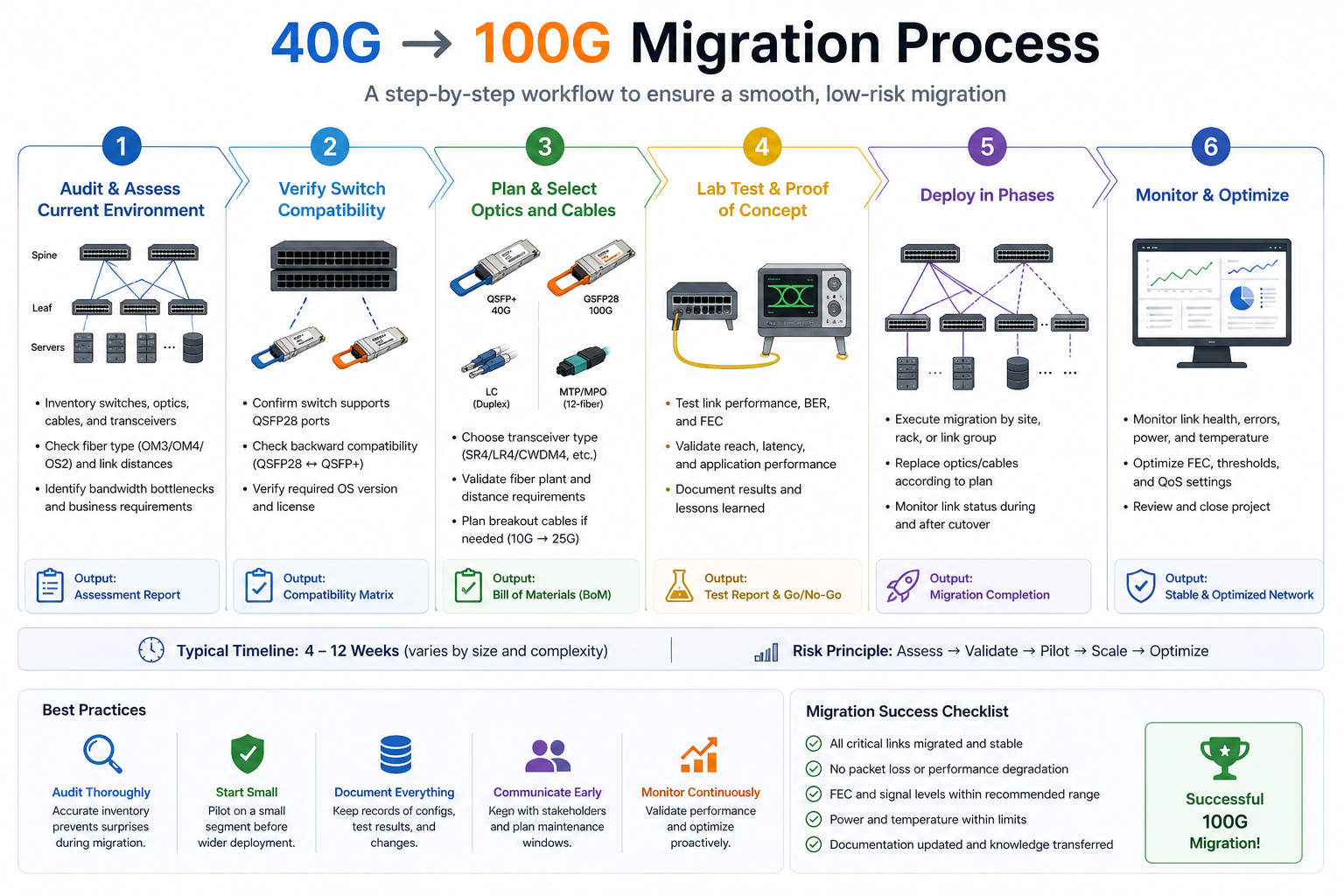
Step-by-Step 40G to 100G Migration Checklist
Step 1: Audit Current Fiber and Distance
Designate the fiber type, connector type, and measured distance for every link you plan to upgrade. Avoid relying on floor plans. Use an OTDR or calibrated optical power meter to verify actual loss and distance.
Step 2: Verify Switch QSFP28 Support and Breakout Modes
Your target switches should be verified for QSFP28 support to achieve the necessary port density. Be sure to confirm that drivers for the 4×25G server access links support breakout mode. On Cisco-related products, consult the Optics-to-Device Compatibility Matrix and, on other product brands, use the respective vendor’s hardware compatibility tool.
Step 3: Select QSFP28 Module Types
Match module types to your fiber and distance requirements:
- •≤100 meters over OM4: QSFP28 SR4
- •≤2 kilometers over SMF: QSFP28 CWDM4
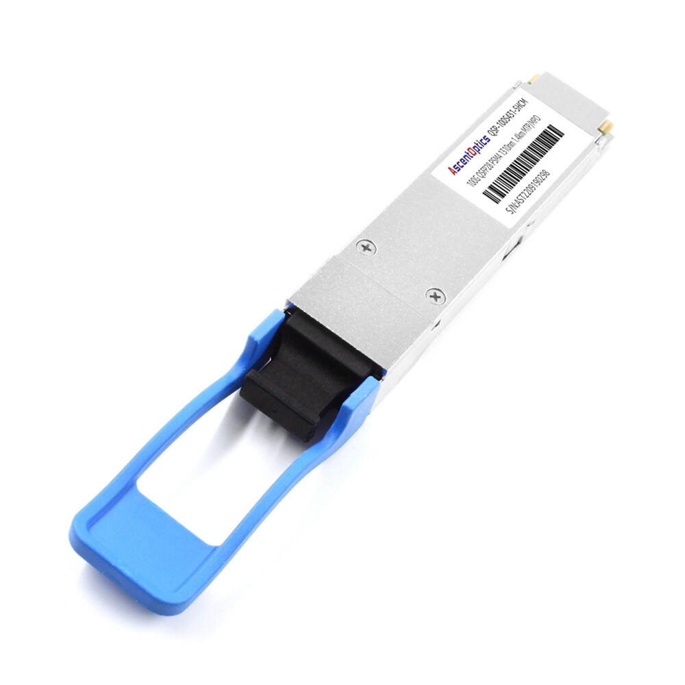
- •≤10 kilometers over SMF: QSFP28 LR4
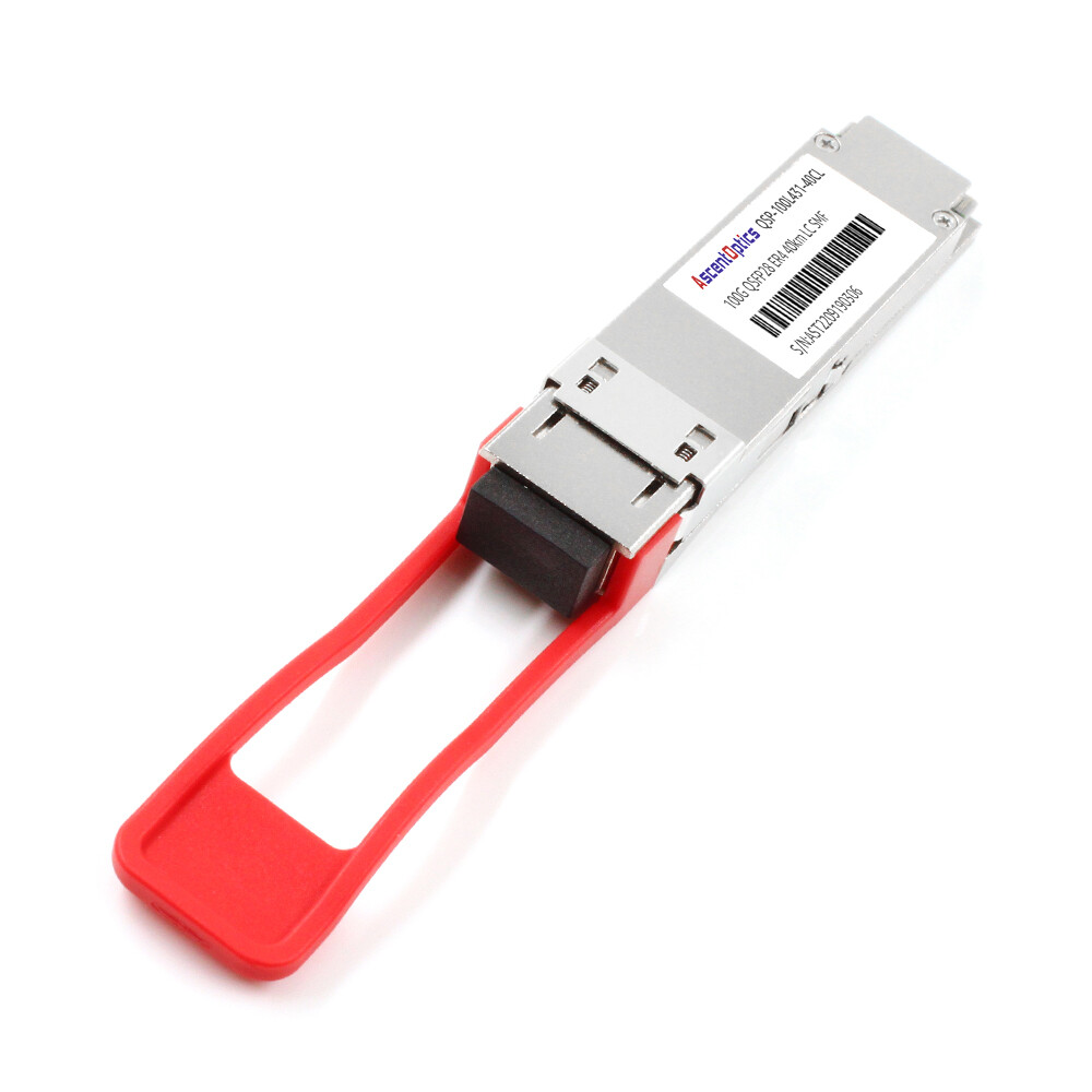
- •≤40 kilometers over SMF: QSFP28 ER4
For module selection details, refer to our QSFP28 module types guide.
Step 4: Test in a Non-Production Environment
Test thoroughly in a non-production environment with the exact switch, module, cable, and endpoint equipment. Validate link stability, FEC, and DDM readings.
Step 5: Plan the Cutover Window
If the link cannot be migrated online, schedule the migration for after hours. Migrate one link at a time for spine-to-spine links using ECMP multipath without any service disruption.
Step 6: Monitor Post-Migration Performance
After cutover, monitor interface counters, error rates, latency, and DDM temperature for at least 72 hours. Early detection of marginal links prevents outages later.
Common Migration Pitfalls and How to Avoid Them
The OM3 Distance Trap
The 40G SR4 goes the length of 100m of OM3, whereas the 100G SR4 would only be operational to 70m of OM3. Consider converting either your 40G optical connections to a minimum of OM4 or to single-mode if the links exceed 70m and are not to be replaced before coming in with optics.
The Breakout Mode Surprise
Not all QSFP28 ports support 4x25G breakout. Some platforms restrict breakout to specific port groups or require specific firmware version. Verify breakout support for each port before ordering cables.
The FEC Mismatch
One of the prime causes of link flapping, which is a quite common happening, is the mismatching of Forward Error Correction protocols between switches and adapter cards. Therefore, ensure that optical links are set to match (either FC-FEC or RS-FEC) for error correction code on both ends.
The Thermal Overload
A fully loaded high-density switch running 5.5W modules can exceed your rack cooling capacity. Recalculate thermal loads before migration.
Conclusion
A successful 40G to 100G migration is not just about buying faster optics. It is a coordinated upgrade of cabling, switches, power budgets, and thermal design. Get any of these wrong, and you face costly delays, recabling projects, or link failures.
Key takeaways:
- •Start with a fiber audit. OM3, OM4, and single-mode have very different 100G distance limits.
- •Choose the phased approach. Upgrade core switches first and reuse 40G optics in QSFP28 ports.
- •Match breakout cables to the new speed. QSFP28-to-4×SFP28 replaces QSFP+-to-4×SFP+.
- •Verify FEC settings on every cross-vendor link.
- •Recalculate power and thermal loads before loading high-density switches.
- •Test everything in a lab before touching production.
Ready to start your migration? Explore Ascent Optics’ QSFP28 transceiver solutions and request a quote for your upgrade project. For a complete overview of 100G networking, read our QSFP28 transceiver guide. And if you are looking ahead to 400G, see our guide on how to choose QSFP-DD modules.
Frequently Asked Questions
Q1. What is the best strategy to move from 40G to 100G?
Phase hybrid migration is ideal for most organizations. The recommendation is to install 100G-ready switches in the core first, maintain the usage of 40G optics but now in QSFP28 ports during transition, and gradually upgrade the remainder of the optics module by module.
Q2. Use of the same fiber for migration from 40G to 100G?
Yes in many cases. LR4 links on single-mode fiber (up to 10 km) can usually be reused. SR4 links require OM4 fiber for full 100-meter reach. OM3 fiber only supports 100G SR4 up to ~70 meters and may require recabling.
Q3. What is the difference between QSFP+ and QSFP28?
QSFP+ carries 40G on four 10G lanes, and QSFP28 carries 100G on four 25G lanes. Form factors being the same, QSFP28 mandates a switch ASIC supporting 25G NRZ signaling mode. Go to our QSFP28 vs QSFP+ literature for more details.
Q4. Do I need new breakout cables with 100G?
Indeed, QSFP+ breakout cables distribute 40G into four 10G SFP+ links. QSFP28 breakout cables split 100G into four 25G SFP28 links. Since signaling rates differ, these cables are in no way interchangeable.
Q5. Can I mix 40G and 100G in the same switch?
Yes. By now, most present-day QSFP28 switches are equipped with backward compatibility with 40G QSFP+ modules. This enables a mixed-speed environment during the transition.
Q6. How much more power does 100G use compared with 40G?
QSFP28 modules typically draw 3.5 W–5.5 W, while QSFP+ modules draw 1.5 W–3.5 W. In a fully loaded 64-port switch, the optics alone can add 100 W–200 W of extra power consumption.
Q7. What switches to select for 100G migration?
Cisco Nexus 9300 series is popular for enterprise environments. Arista 7060X4 excels in low-latency and hyperscale deployments. Juniper QFX series offers strong fabric performance, while NVIDIA Spectrum platforms are preferred for AI and HPC clusters.
IEEE 802.3bm standards
Cisco Optics-to-Device Compatibility Matrix
Post Views: 1,092