As network speeds move from 400G to 800G and now toward 1.6T, power consumption has become one of the biggest challenges in optical networking. In modern AI clusters and hyperscale data centers, optics are no longer a small part of the switch power budget. High-speed transceivers can account for a significant share of total system power and thermal load, especially in dense 800G deployments.
Many operators first encounter this problem during large-scale upgrades. A switch platform that was originally designed for lower-power 400G optics may suddenly face airflow limitations after deploying 800G DSP-based modules. Rack power density rises quickly, cooling margins shrink, and thermal planning becomes far more complex than expected.
This is why understanding OSFP power consumption is now essential for network architects, data center operators, and AI infrastructure teams. Different OSFP modules can vary dramatically in power draw depending on reach, modulation technology, DSP architecture, and optical engine design. A low-power 800G LPO module may consume under 8 watts, while a coherent 800G ZR module can exceed 25 watts.
This guide provides exact OSFP power consumption specifications across 400G, 800G, and 1.6T data rates. You will learn module-by-module wattage, how OSFP compares to QSFP-DD on power, what the OSFP MSA power classes mean in practice, and how to calculate accurate power budgets for your switches and racks.
What Is OSFP and Why Does Power Matters
OSFP stands for Octal Small Form-factor Pluggable. It is an optical transceiver form factor designed to support 400G, 800G, and future 1.6T data rates using eight electrical lanes. The OSFP MSA developed the specification with input from Google, Arista, and other major networking vendors.
The form factor is slightly larger than QSFP-DD, measuring approximately 22.5 mm in width compared to 18.35 mm. This extra size is not accidental. OSFP was intentionally designed with a larger thermal envelope to support higher power consumption as data rates increase.
Power consumption has become the single most critical infrastructure concern for high-speed optical networks. At 400G and above, optical transceivers can consume more power than the switch ASICs they connect to. In a fully loaded 32-port 800G switch, optics alone can account for over 50% of the total power draw. For data center operators, this translates directly into higher electricity costs, increased cooling requirements, and reduced rack density.
Understanding OSFP power consumption is not just a technical exercise. It is a fundamental requirement for accurate data center planning, thermal design, and total cost of ownership calculations.
OSFP Power Consumption by Data Rate
OSFP power consumption varies significantly depending on module type, transmission distance, DSP complexity, and optical architecture. Short-reach multimode modules consume much less power than long-haul coherent optics.
400G OSFP Power Consumption Specifications
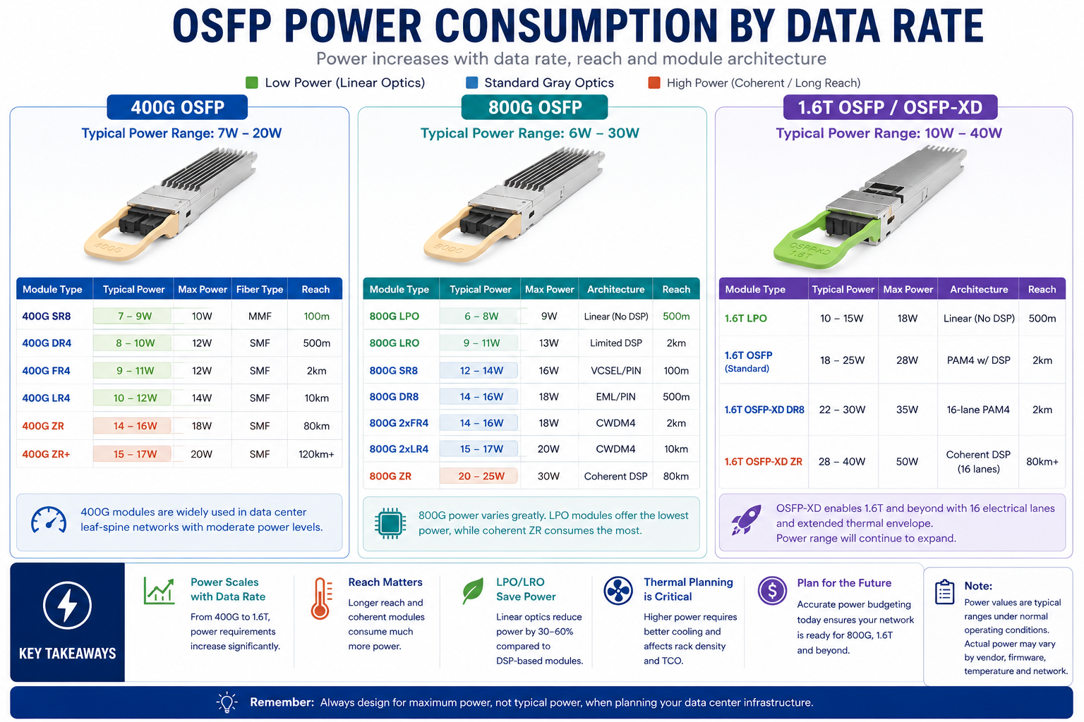
400G OSFP modules represent the entry point into the OSFP ecosystem. Power consumption at this data rate is relatively manageable, though it still exceeds most older form factors.
400G OSFP modules represent the first major generation of OSFP deployments. Most standard 400G gray optics operate within manageable thermal limits and are widely supported across modern switch platforms.
Standard direct-detect optics such as SR8, DR4, and FR4 generally operate between 8 and 12 watts. These modules rely on PAM4 modulation with moderate signal processing requirements.
400G SR8 modules typically consume the least power because they use VCSEL-based multimode optical engines designed for short-reach connectivity inside data centers. DR4 and FR4 modules consume slightly more power due to the use of single-mode optics and wavelength multiplexing.
Power consumption rises substantially for coherent optics. 400G ZR and ZR+ modules require advanced coherent DSPs capable of dispersion compensation and long-distance transmission. These modules commonly operate above 18 watts and require careful thermal validation.
For most standard leaf-spine data center deployments using DR4 or FR4 modules, thermal requirements remain relatively manageable. A fully populated 32-port 400G switch using 10W optics typically consumes around 320W from transceivers alone.
800G OSFP Power Consumption Specifications
The transition from 400G to 800G significantly increases optical module power consumption. While the increase is not exactly double, most 800G modules consume roughly 60% to 80% more power than comparable 400G optics.
| Module Type |
Typical Power |
Maximum Power |
Architecture |
Reach |
| 800G SR8 |
12-14W |
16W |
VCSEL-based MMF optics |
100m |
| 800G DR8 |
14-16W |
18W |
PAM4 Direct Detect |
500m |
| 800G 2xFR4 |
14-16W |
18W |
Dual FR4 optical engines |
2km |
| 800G 2xLR4 |
15-18W |
20W |
CWDM-based SMF optics |
10km |
| 800G ZR |
20-25W |
30W |
Coherent DSP |
80km |
| 800G LPO |
6-8W |
9W |
Linear (no DSP) |
500m |
| 800G LRO |
9-12W |
14W |
Reduced DSP architecture |
2km |
Standard 800G gray optics typically operate between 14 and 18 watts. Among these, 800G DR8 has become one of the most widely deployed module types for AI clusters and high-density spine networks.
Thermal planning becomes much more important at 800G. A fully populated 32-port 800G switch using 16W optics can consume more than 500W from optics alone. In many deployments, cooling overhead adds another 40% to 60% on top of the raw optical power.
Coherent 800G modules consume even more power because of advanced DSP processing. Depending on link conditions and transmission distance, 800G ZR optics may operate between 20W and 30W.
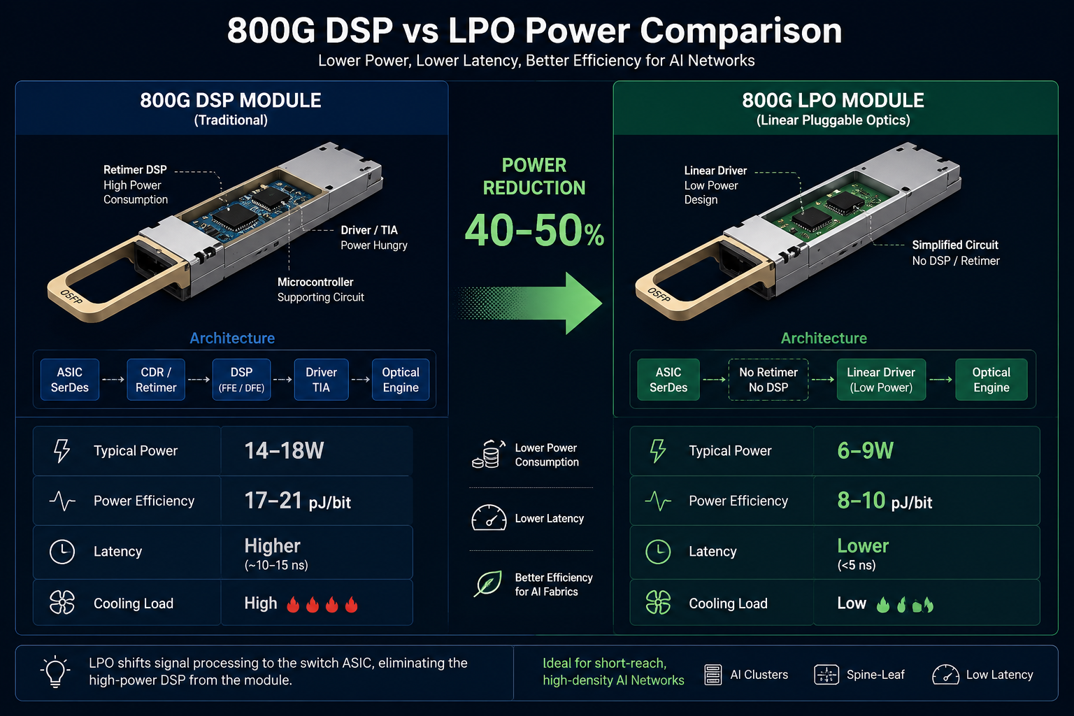
To address rising power consumption, the industry has increasingly focused on Linear Pluggable Optics (LPO). Instead of using a full retiming DSP inside the module, LPO architectures rely on the host switch ASIC for much of the signal conditioning. This can reduce module power consumption by approximately 40% to 50% compared with conventional DSP-based designs.
As a result, many hyperscale AI deployments now use LPO modules for short-reach interconnects where lower power and lower latency provide operational advantages.
1.6T OSFP and OSFP-XD Power Specifications
The next generation of high-speed optical networking is moving toward 1.6T connectivity. As bandwidth increases, thermal density and power delivery become even more critical.
| Module Type |
Typical Power
|
Maximum Power |
Form Factor |
Notes
|
| 1.6T OSFP (standard) |
18-22W
|
25W |
OSFP |
8x200G PAM4
|
| 1.6T OSFP-XD DR8 |
22-26W
|
30W |
OSFP-XD |
Extended thermal
|
| 1.6T OSFP-XD ZR |
28-35W
|
40W |
OSFP-XD |
Coherent optics
|
| 1.6T LPO |
10-14W
|
16W |
OSFP |
Linear architecture
|
Standard 1.6T modules using early-generation DSPs generally consume between 18W and 22W. Newer DSP process nodes, including 3nm designs demonstrated at recent OFC events, are helping reduce power consumption and improve thermal efficiency.
The OSFP-XD form factor is being developed specifically to support future ultra-high-power modules. Compared with standard OSFP, OSFP-XD provides additional internal volume and improved thermal capacity for coherent optics and future 3.2T platforms.
At the same time, linear optical architectures are becoming increasingly important for AI fabrics. Early 1.6T LPO demonstrations have shown substantial reductions in both power consumption and latency, although these solutions still depend heavily on advanced host ASIC capabilities.
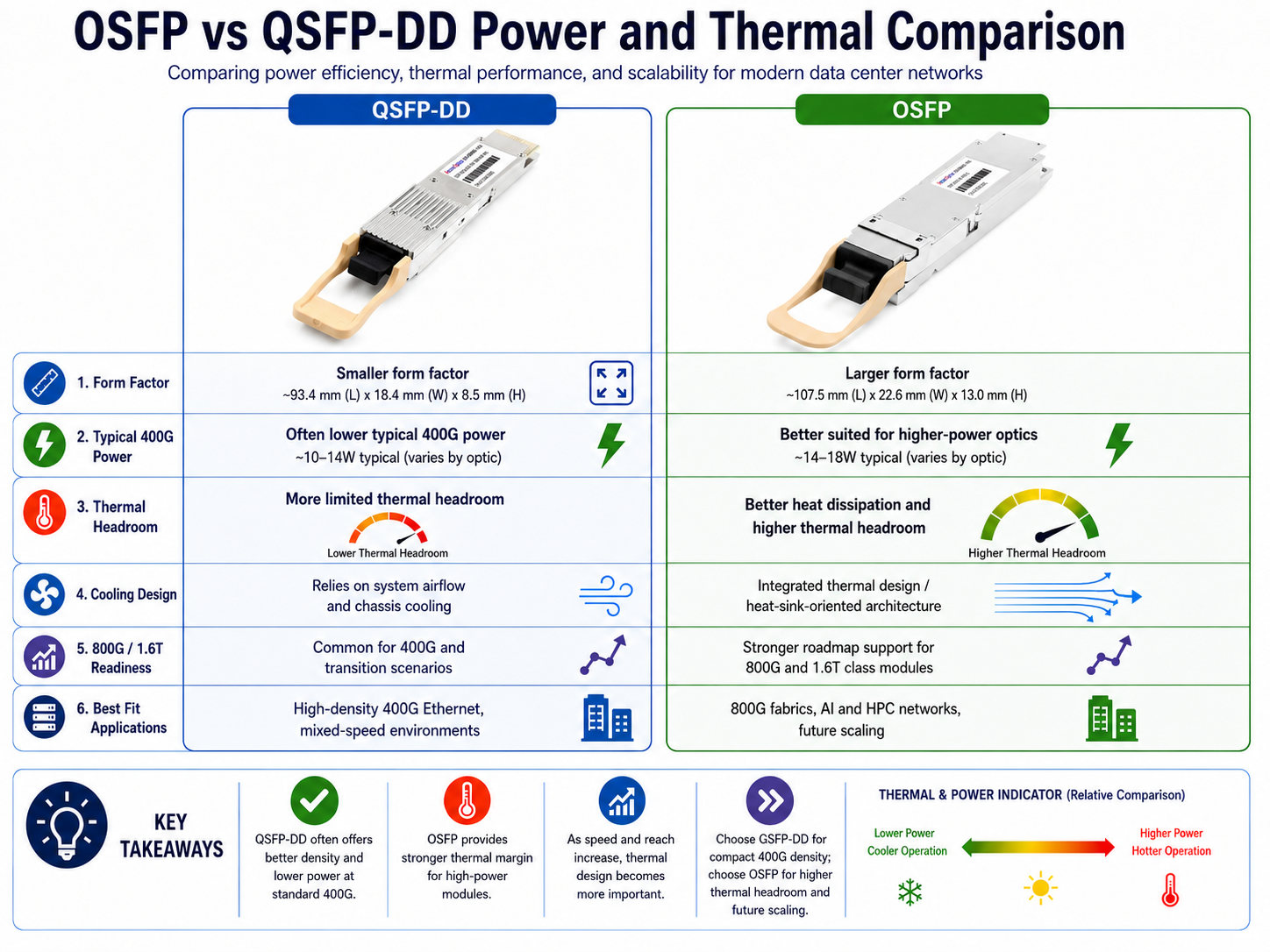
OSFP vs QSFP-DD: Power and Thermal Comparison
Network architects frequently compare OSFP and QSFP-DD when evaluating OSFP vs QSFP-DD power and performance for 400G or 800G networks. Power consumption and thermal capacity are often decisive factors in this choice.
Direct Power Comparison
| Specification |
QSFP-DD
|
OSFP
|
| 400G typical power |
8-12W
|
8-14W
|
| 800G typical power |
12-18W
|
14-18W
|
| Maximum thermal capacity |
18-20W
|
~20–25W+
|
| Form factor width |
18.35mm
|
22.5mm
|
| Cooling design |
Compact
|
Larger thermal envelope
|
It is important to understand that power consumption is not determined entirely by the form factor itself. Instead, power depends primarily on the optical architecture, DSP design, and module implementation.
However, OSFP deployments are often associated with higher-power optics because the larger form factor provides better thermal headroom and allows more aggressive cooling.
For standard 400G deployments using SR4, DR4, or FR4 optics, QSFP-DD often provides better port density and slightly lower overall thermal requirements. For high-power coherent optics, 800G deployments, and future 1.6T systems, OSFP generally offers superior airflow and thermal dissipation. This makes it especially attractive for AI clusters and high-density spine fabrics.
Many modern switch platforms now support both form factors, allowing operators to choose the best option for each deployment scenario.
When QSFP-DD Power Efficiency Matters More
QSFP-DD power consumption is typically lower, making it the better choice from a pure power perspective when:
- •Deploying standard 400G SR/DR/FR optics where power is below 12 watts
- •Maximizing port density is a priority
- •Backward compatibility with existing QSFP28 infrastructure is required
- •The network operates in well-controlled data center environments with ample cooling
When OSFP Thermal Headroom Wins
OSFP becomes the preferred choice when:
- •Deploying coherent 400G ZR+ or 800G modules where power exceeds 15 watts
- •Planning for future 800G or 1.6T upgrades on the same switch platform
- •Operating in high-density AI/HPC clusters where OSFP thermal managementis challenging
- •Long-term reliability in high-power configurations is critical
The choice is not always binary. Some switch vendors offer platforms that support both form factors, allowing network architects to select the optimal module for each specific connection based on reach, power, and density requirements.
Need a detailed comparison of both form factors? Our complete QSFP-DD vs OSFP guide covers dimensions, compatibility, density, and migration strategies in depth.
Understanding OSFP Power Management
The OSFP MSA defines a structured power management framework that allows hosts and modules to coordinate safe power delivery.
OSFP modules communicate with the host using the CMIS management interface. During initialization, the module advertises its required power level and operational capabilities. The host system then determines whether enough electrical and thermal capacity is available before enabling full-power operation.
Low Power Mode vs High Power Mode
OSFP modules operate in two distinct power states:
Low Power Mode: In this state, the module draws no more than 1.5 watts and keeps its optical transmitters disabled. The module remains in Low Power Mode when any of the following conditions are true:
- •The M_RSTn (reset) signal is asserted
- •The M_LPWn (low power) signal is asserted
- •The ForceLowPwr bit is set in CMIS register space
High Power Mode: The host transitions the module to High Power Mode by de-asserting all three control signals. Only then can the module enable its transmitters and draw full operational power. This staged power-up prevents inrush current spikes and allows the host to verify that the module’s power class is within the port’s thermal budget before enabling full operation.
Voltage and Current Specifications
OSFP modules operate from a 3.3V DC supply with a tolerance of ±5%. The OSFP specification includes multiple VCC power pins capable of delivering substantial current.
In theory, the electrical delivery capability exceeds 30W, although actual switch support depends on system design, airflow capability, and thermal validation. High-power 800G and 1.6T platforms require careful PCB design, copper power distribution, and heatsink engineering to ensure stable operation.
Reducing OSFP Power: LPO, LRO, and Emerging Technologies
As data rates climb and OSFP module power budgets tighten, the optical networking industry has developed several approaches to reduce consumption.
Linear Pluggable Optics (LPO)
LPO removes the full retiming DSP found in conventional pluggable optics and instead relies more heavily on the host ASIC for signal processing.
Because DSPs are among the largest contributors to optical module power consumption, reducing DSP complexity can significantly improve efficiency.
| Architecture |
800G Module Power |
Energy per Bit |
Relative Latency |
| Standard DSP |
14-18W |
~17-21 pJ/bit |
Higher |
| LPO |
6-9W |
~8-10 pJ/bit |
Lower |
| LRO |
9-12W |
~12-14 pJ/bit |
Moderate |
Compared with standard DSP-based optics, LPO can reduce power consumption by roughly 40% to 50%.
In large-scale AI clusters, these savings become extremely important. Lower optical power reduces:
- •Switch thermal load
- •Fan speed requirements
- •Rack cooling demand
- •Facility electricity costs
LPO also offers lower latency because signal processing stages are reduced.
However, LPO has limitations. Without a full onboard DSP, these modules are generally best suited for short and predictable links. Signal integrity requirements are much stricter, and interoperability depends heavily on host ASIC design.
Linear Receive Optics (LRO)
LRO provides a compromise between conventional DSP optics and pure LPO. Instead of removing DSP functionality entirely, LRO reduces DSP complexity on the receive side while preserving better compatibility and signal robustness.
As a result, LRO modules typically consume less power than full DSP optics while maintaining greater deployment flexibility than LPO.
Advanced DSP Process Nodes
Another major source of efficiency improvement comes from semiconductor manufacturing advances. Newer DSP chips built on 3nm process technology can reduce optical module power consumption while improving signal processing performance. As the industry moves toward smaller process nodes, additional efficiency gains are expected for future 1.6T and 3.2T optics.
Silicon Photonics Integration
Silicon photonics is also helping improve power efficiency. By integrating optical functions directly onto silicon-based photonic engines, vendors can reduce electrical loss, simplify packaging, and improve overall thermal performance.
Many next-generation 1.6T optical modules now incorporate silicon photonics technologies to support higher bandwidth within realistic thermal limits.
Data Center Power Planning with OSFP
Accurate power budgeting for OSFP-compatible switches is essential for successful deployment. The following framework helps network architects calculate power requirements at the switch, rack, and facility levels.
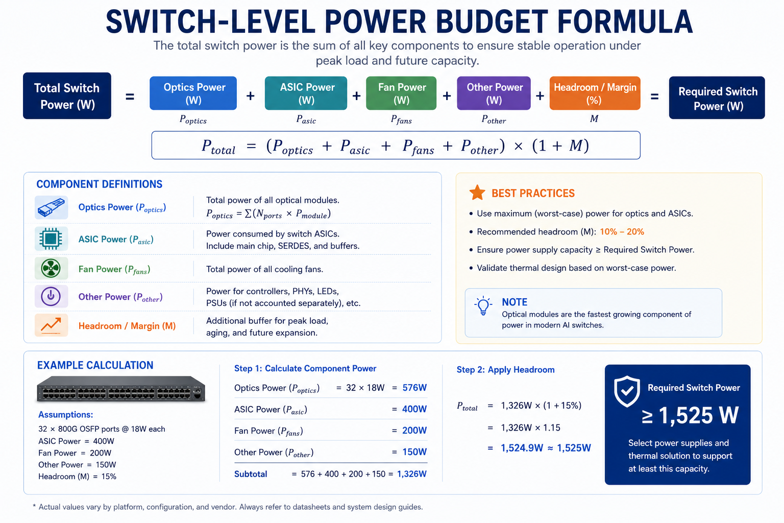
Switch-Level Power Budgeting
To calculate the total power draw of an OSFP-equipped switch, use this formula:
Total Switch Power = Base Switch Power + Optical Power + Cooling Overhead
For example, consider a 32-port 800G switch fully populated with 800G DR8 modules:
- •Base switch power: ~400W
- •Optical power: 32 × 16W = 512W
- •Cooling overhead: ~256W
- •Total estimated power: ~1,168W
If the same switch used LPO modules at 8 watts each:
- •Optics power: 32 ports x 8W = 256W
- •Cooling overhead: 256W x 0.5 = 128W
- •Total: approximately 784W
This represents a reduction of nearly 33% in total switch power consumption.
Rack-Level Power Planning
At the rack level, multiply the switch total by the number of switches per rack and add infrastructure overhead:
| Configuration |
Switches per Rack
|
Optics-Only Power |
Total with Cooling
|
| 400G OSFP, 32-port |
4
|
1,280W |
1,920W
|
| 800G OSFP, 32-port |
4
|
2,048W |
3,072W
|
| 800G LPO, 32-port |
4
|
1,024W |
1,536W
|
| 1.6T OSFP-XD, 32-port |
4
|
2,880W |
4,320W
|
These figures represent optics and cooling only. Add server, storage, and network equipment power to determine total rack requirements. A rack with four 800G OSFP switches can easily exceed 5 KW just from networking equipment, requiring careful coordination with facilities teams.
Cooling Challenges for 1.6T Optics
As optical modules approach 30W to 40W thermal envelopes, traditional air-cooling designs become increasingly difficult.
Future 1.6T and coherent optical deployments may require:
- •Higher airflow fan systems
- •Advanced heatsink structures
- •Liquid-assisted cooling
- •Rear-door heat exchangers
- •Improved rack airflow containment
Some hyperscale operators are also investigating co-packaged optics, where optical engines are integrated directly with switch ASICs to reduce electrical trace loss and improve overall efficiency.
Although co-packaged optics are still emerging, they highlight how serious thermal scaling challenges have become in next-generation AI networking.
Five-Year TCO Impact
Electricity costs add significantly to the total cost of ownership for high-power optical modules. At an average commercial electricity rate of $0.12 per kWh:
| Module Type |
Annual Power Cost (per port)
|
5-Year Power Cost
|
| 400G DR4 (10W) |
$10.51
|
$52.55
|
| 800G DR8 (16W) |
$16.81
|
$84.05
|
| 800G LPO (8W) |
$8.41
|
$42.05
|
| 1.6T OSFP (22W) |
$23.12
|
$115.60
|
When the cooling multiplier is included, the 5-year energy cost for a single 800G DR8 port approaches $126 per port over five years.
For a 1,000-port deployment, this represents approximately $126,000 in combined power and cooling costs. This is why many hyperscale operators are aggressively adopting LPO for short-reach connections. The power savings directly reduce both electricity bills and cooling infrastructure requirements.
Planning a network upgrade? Our engineers can help you calculate accurate power budgets for your specific switch and module configurations. Contact our optical networking team for a detailed assessment.
Conclusion
OSFP power consumption ranges from approximately 7 watts for a 400G SR8 module to over 30 watts for an 800G ZR coherent transceiver. At 1.6T, standard modules draw 18-22 watts while high-power OSFP-XD variants can reach 40 watts. These figures are not abstract specifications. They directly determine data center cooling requirements, rack density, electricity costs, and total cost of ownership.
Key takeaways for network architects:
- •Standard 400G OSFP gray optics consume 8-12 watts, well within most switch thermal budgets
- •800G OSFP modules typically draw 14-18 watts, making thermal planning essential
- •LPO architectures can reduce 800G module power by 40-50%, saving significant energy at scale
- •OSFP provides superior thermal headroom compared to QSFP-DD for high-power modules
- •Always budget for maximum power consumption, not typical values
- •The 5-year energy cost of powering and cooling high-speed optics can exceed 15% of module purchase price
Selecting the right OSFP module requires balancing reach, power, compatibility, and cost. For short-reach data center connections, LPO offers compelling power savings. For long-haul or DCI applications, standard DSP modules remain necessary despite higher power draw. Understanding these trade-offs enables informed decisions that align optical connectivity with your infrastructure constraints.
Ascent Optics provides a comprehensive range of OSFP transceiver modules from 400G to 800G, including standard DSP, LPO, and LRO variants. Our engineering team helps customers select the optimal module for each application based on reach, power budget, and switch compatibility requirements. Request a quote for your next OSFP deployment.
Frequently Asked Questions About OSFP Power Consumption
What is the maximum power an OSFP port can supply?
The OSFP MSA Rev 5.0 specification allows hosts to deliver over 30 watts to a module through four VCC pins rated at 2.5 amps each at 3.3 volts. In practice, most switches are designed to support 15-20 watts per port, with high-end platforms supporting up to 25 watts for coherent modules.
How much power does a typical 400G OSFP module use?
Standard 400G OSFP modules such as SR8, DR4, and FR4 typically consume 8-12 watts. Coherent variants such as 400G ZR draw 14-18 watts. The exact value depends on the module type, fiber conditions, and ambient temperature.
Does OSFP use more power than QSFP-DD?
For equivalent module types, OSFP typically consumes 2-3 watts more per port than QSFP-DD at 400G. However, OSFP supports higher maximum power and provides better thermal dissipation, making it more suitable for high-power coherent modules and 800G/1.6T applications.
Can OSFP modules overheat?
Yes, if the host switch lacks adequate thermal design for the installed modules. The OSFP MSA specifies a case temperature range of 0C to 70C for commercial modules. Exceeding this range can degrade performance, increase error rates, and reduce module lifetime. Proper airflow, heat sink contact, and rack-level cooling are essential.
What are OSFP power classes?
The OSFP MSA defines eight power classes (Class 1 through Class 8) that categorize modules by maximum power draw. Classes 1-3 are used for initialization and low-power states. Classes 4-6 cover standard 400G modules. Classes 7-8 support 800G and 1.6T modules up to 18 watts and beyond.
How does LPO reduce OSFP power consumption?
LPO eliminates the DSP chip from the transceiver, reducing 800G module power from 14-18 watts to 6-9 watts. The trade-off is reduced reach (typically 500m or less) and a requirement for host switches with linear-capable SerDes.
Should I plan for typical or maximum power consumption?
Always budget for maximum power consumption. Poor fiber conditions, higher ambient temperatures, and FEC overhead can increase actual power draw by 2-4 watts per module above typical values. Planning for worst-case ensures adequate thermal and electrical capacity.
OSFP msa
Post Views: 2,361


