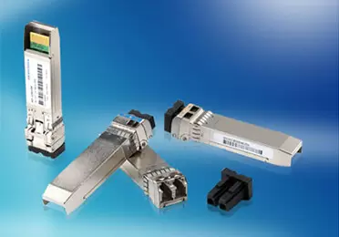
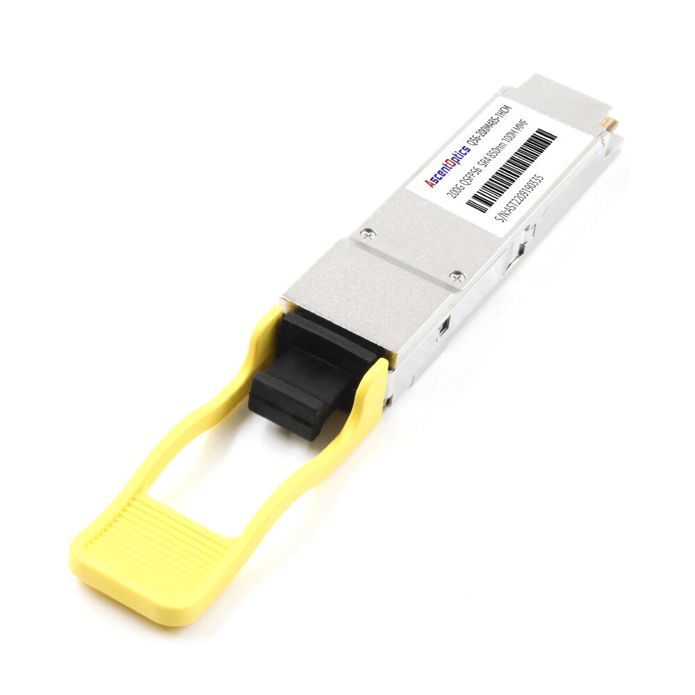
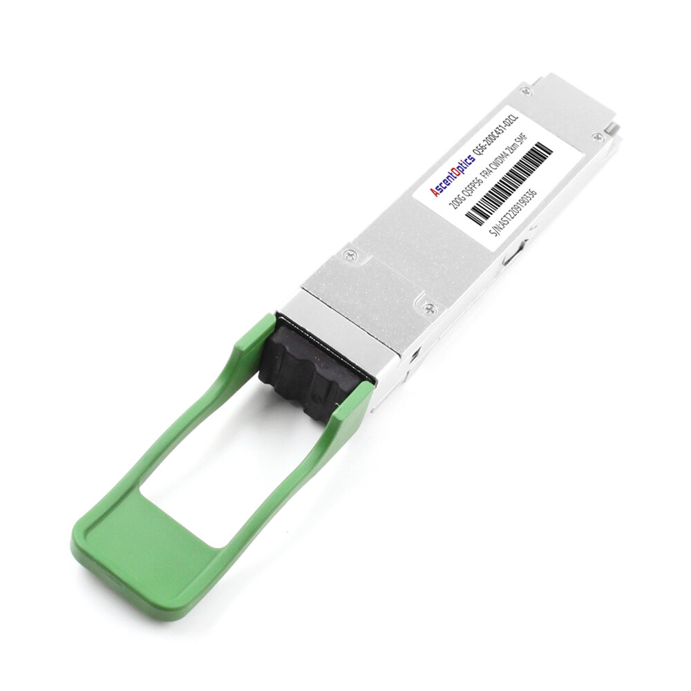
The QSFP56 optical module series encompasses SR4 (multimode, 100m), DR4 (singlemode, 500m), FR4 (2km), LR4 (10km), and ER4 (40km) variants, addressing transmission requirements ranging from intra-data center links to metropolitan networks. LPO (Linear Pluggable Optics)—an emerging low-power solution—eliminates the need for DSPs or CDRs, thereby significantly reducing latency and power consumption, making it ideal for short-reach, high-speed interconnects.
With their distinct specifications regarding transmission distance, fiber type, and power consumption, these modules collectively form a flexible 200G Ethernet ecosystem that facilitates the efficient deployment of next-generation networks.
What Is QSFP56?
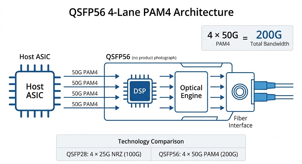
QSFP56 (Quad Small Form-Factor Pluggable 56) is a hot-pluggable optical transceiver that supports 200 Gigabit Ethernet using four 50 Gbps electrical lanes. Unlike QSFP28, which uses NRZ signaling at 25 Gbps per lane, QSFP56 uses PAM4 modulation to pack two bits per symbol and double the bit rate without adding lanes. The result is 200 Gbps of aggregate bandwidth in the same mechanical package as a 100G QSFP28 module. If you’re new to 200G networking, our 200G QSFP56 complete guide explains the QSFP56 architecture, signaling technology, and common deployment scenarios in greater detail.
A QSFP56 transceiver is a hot-pluggable optical module that supports 200 Gigabit Ethernet using four 50 Gbps PAM4 electrical lanes. QSFP56 module types include SR4 for short-reach multimode, DR4 for 500 m parallel single-mode, and FR4/LR4/ER4 for longer single-mode reaches.
Because the mechanical envelope is unchanged, QSFP56 modules fit into the same cages and cable assemblies as QSFP28. However, electrical compatibility is not automatic. A QSFP56 module requires a host ASIC capable of 200GAUI-4 PAM4 signaling and FEC support. A QSFP28 module will often work in a QSFP56-capable port, but the reverse is not true.
Key standards that govern QSFP56 operation include:
- •IEEE 802.3bs-2017— defines 200GBASE-DR4, 200GBASE-FR4, 200GBASE-LR4, and the 200GAUI-4 electrical interface.
- •IEEE 802.3cd-2018— adds 200GBASE-SR4 for multimode fiber.
- •QSFP56 MSA— governs mechanical dimensions, pinout, and digital diagnostics.
- •SFF-8665 / SFF-8679— specify the QSFP mechanical and electrical signaling requirements.
- •CMIS 4.0 — provides the common management interface for DOM/DDM readings.
QSFP56 Module Types at a Glance
The most common QSFP56 module types are named after their IEEE reach classes. Each variant uses a specific fiber type, wavelength, and connector, which determines both cost and deployment scenario. The table below summarizes the core specifications.
| Module Type |
Fiber |
Wavelength |
Connector |
Typical Reach |
Typical Power |
Best Use Case |
| SR4 |
OM3/OM4/OM5 MMF |
850 nm |
MPO-12 |
70 m OM3 / 100 m OM4 / 150 m OM5 |
3.3–5 W |
Intra-rack / row-to-row data center |
| DR4 |
SMF |
1310 nm |
MPO-12 |
500 m |
5–5.5 W |
Spine links, 4×50G breakout |
| FR4 |
SMF |
CWDM4 1271–1331 nm |
Duplex LC |
2 km |
5.5–6.5 W |
Campus/metro DCI |
| LR4 |
SMF |
LWDM4 1295–1309 nm |
Duplex LC |
10 km |
6.5–7.5 W |
Long-haul DCI / WAN edge |
| ER4 |
SMF |
LWDM4 1295–1309 nm |
Duplex LC |
40 km |
8–9 W |
Telecom backhaul |
| LPO-SR4 |
OM4/OM5 MMF |
850 nm |
MPO-12 |
100 m OM4 / 150 m OM5 |
~2.5 W |
AI/ML clusters, power-limited cages |
200GBASE-SR4: The Short-Reach Workhorse
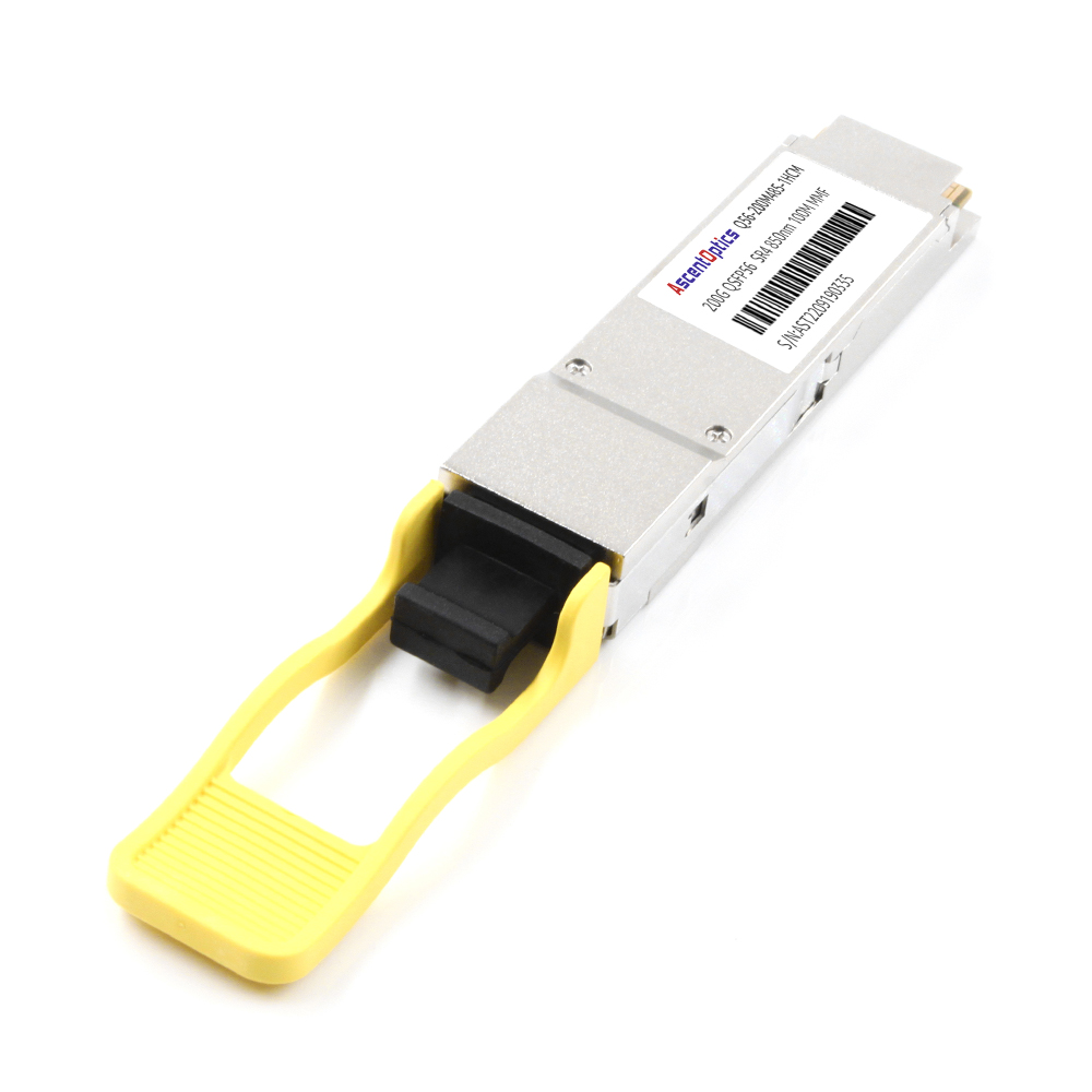
200GBASE-SR4 is the most widely deployed QSFP56 module type for data centers. It uses vertical-cavity surface-emitting laser (VCSEL) transmitters at 850 nm over multimode fiber. The MPO-12 connector carries four transmit and four receive fibers in a parallel configuration.
Typical reach depends on the fiber grade:
- •OM3: up to 70 m
- •OM4: up to 100 m
- •OM5: up to 150 m
Power consumption usually falls between 3.3 W and 5 W, making SR4 the most power-efficient standard QSFP56 module type. It is also the lowest-cost option because VCSELs and multimode fiber are less expensive than single-mode counterparts.
SR4 is the natural choice when servers, leaf switches, and spine switches sit in the same data hall. Many organizations reuse existing OM4 cabling when upgrading from 100G QSFP28 SR4 to 200G QSFP56 SR4, which simplifies migration and protects prior fiber investments.
However, SR4 requires clean MPO-12 connectors and proper polarity. PAM4 signaling has a lower noise margin than NRZ, so insertion loss and contamination matter more than they did at 100G. A dirty connector that would pass at 25 Gbps per lane can cause CRC errors or link flapping at 50 Gbps per lane.
200GBASE-DR4: Parallel Single-Mode for Spine Fabrics
200GBASE-DR4 moves from multimode to single-mode fiber and extends reach to 500 m. It uses an MPO-12 connector with four parallel lanes at 1310 nm. The key advantage over SR4 is not just distance; DR4 also supports breakout to four 50 Gbps connections.
A 200G QSFP56 DR4 module can be split into 4 × 50G SFP56 links. This makes DR4 popular in spine fabrics that fan out to lower-speed leaf switches or servers. It also provides a cleaner cabling plant than multiple separate 50G links when the physical distance exceeds multimode limits.
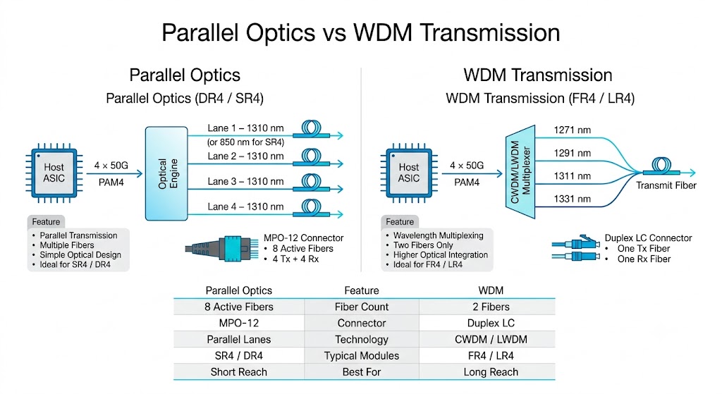
Power consumption for DR4 is typically 5 W to 5.5 W. The jump from SR4 is modest, but the shift to single-mode fiber adds cable cost. Because DR4 uses parallel optics, it is not wavelength-division multiplexed; each fiber carries one lane. That simplifies optical design but requires an MPO-12 trunk rather than a simple duplex LC patch.
200GBASE-FR4: CWDM4 for Campus and Metro DCI
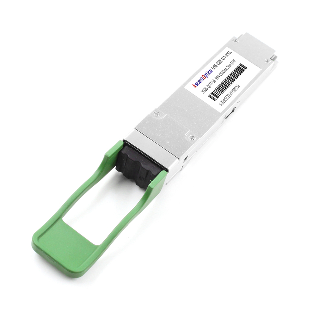
200GBASE-FR4 is the first QSFP56 module type in the family to use wavelength-division multiplexing. It combines four lanes on a single pair of single-mode fibers using CWDM4 wavelengths: 1271 nm, 1291 nm, 1311 nm, and 1331 nm. The duplex LC connector is the same style used in 10G and 100G long-reach optics, so many data center teams already have the patching tools and cleaning kits.
FR4 supports a reach of up to 2 km. That makes it ideal for campus interconnects, metro data center links, and enterprise core-to-distribution connections. Because the four lanes are multiplexed inside the module, the external fiber plant is simpler than DR4: one transmit fiber and one receive fiber per link. Compared with DR4, FR4 reduces fiber count from eight fibers to only two fibers, simplifying structured cabling for campus and DCI deployments.
FEC is required for FR4 operation. Most host switches implement KP4-FEC (RS 544,514) for PAM4 links, but the setting must be enabled and matched on both ends. A common deployment mistake is leaving FEC disabled on one side of an FR4 link, which produces a physically present but error-prone connection.
Typical power consumption for FR4 is 5.5 W to 6.5 W. The added DSP and wavelength multiplexing push it slightly above DR4, but the simplified cabling often offsets that cost in campus-style builds.
200GBASE-LR4: Long-Reach DCI and WAN Edge
200GBASE-LR4 extends single-mode reach to 10 km using LWDM4 wavelengths centered near 1295–1309 nm. It uses a duplex LC connector and is the standard choice for data center interconnects that cross a city or connect regional facilities.
With FEC enabled, some LR4 modules can stretch to 20 km. That extra margin is valuable for service providers and enterprises that need to connect buildings across a metro area without installing intermediate regeneration.
Power consumption for LR4 is typically 6.5 W to 7.5 W. The higher wattage comes from stronger lasers, tighter wavelength control, and more aggressive DSP. In a 32-port switch fully populated with LR4 modules, optics alone can draw over 200 W. Thermal planning matters.
QSFP56 ER4: Extreme Reach for Telecom Backhaul
QSFP56 ER4 is the longest-reach standard QSFP56 module type, supporting up to 40 km over single-mode fiber. It uses the same LWDM4 wavelength plan as LR4 but with higher-output optics and more sensitive receivers.
ER4 is primarily used in telecom backhaul, long-distance enterprise WAN links, and service provider aggregation. It is not typically found inside hyperscale data centers because the distances are shorter and the power penalty is significant.
Power consumption for ER4 is usually 8 W to 9 W per module. In dense switches, that translates to 256 W to 288 W for a full 32-port load. The cost is also three to four times higher than SR4. For that reason, ER4 should be reserved for links where no shorter-reach alternative can cover the distance.
QSFP56 LPO: The Low-Power Option for AI Clusters
Linear Pluggable Optics (LPO) is a newer class of QSFP56 module that removes the DSP from the optical module and moves signal processing to the host switch ASIC. The result is a significant power reduction: an LPO-SR4 module typically draws around 2.5 W, compared to 3.3–5 W for a standard SR4.
Those savings matter most in AI and high-performance computing clusters, where thousands of 200G links connect GPUs and leaf switches. A single large training cluster can contain tens of thousands of optical modules. Cutting per-module power by 1.5 W to 2 W translates to tens of kilowatts of rack-level savings and reduced cooling load.
LPO is not a drop-in replacement for standard QSFP56. The switch ASIC must support LPO operation, and the link budget is tighter because there is no module-side DSP to clean up the signal. LPO also complicates interoperability testing because the module and switch must be qualified together.
For organizations building new AI fabrics with LPO-compatible switches, LPO-SR4 is becoming the default QSFP56 module type. For legacy switches, standard DSP-based modules remain the safer choice.
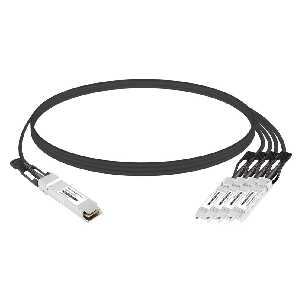
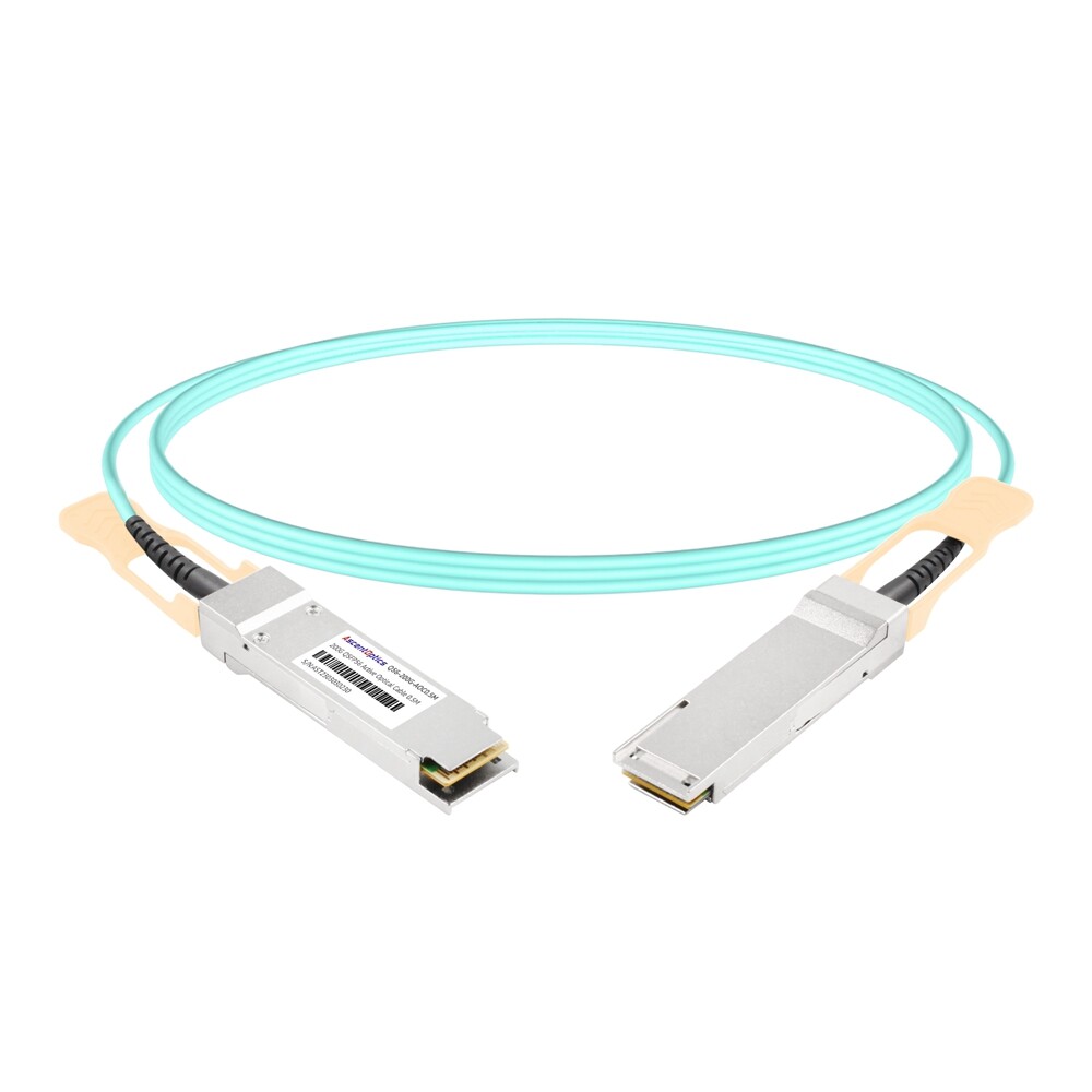
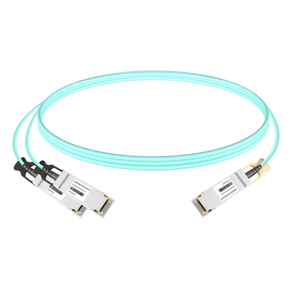
QSFP56 DAC, AOC, and Breakout Cables
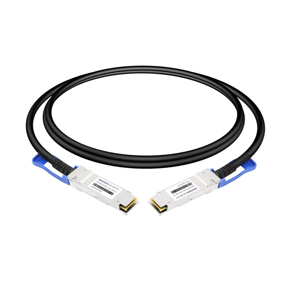
Not every 200G link needs a pluggable transceiver. Direct attach copper (DAC) and active optical cable (AOC) assemblies provide cost-effective options for short connections.
Passive DAC uses copper traces inside the cable assembly to carry electrical signals directly. It is the lowest-cost option but is limited to about 3 m. Passive DAC is common for top-of-rack connections where a server and leaf switch sit in the same cabinet.
Active DAC adds signal conditioning to extend reach slightly, typically up to 5 m. It costs more than a passive DAC but less than an AOC.
AOC replaces copper with fiber and active optical engines in each connector. It supports reaches from 5 m to 50 m and is lighter and more flexible than DAC. AOC is popular for clean cable management in dense racks.
Breakout cables let a 200G QSFP56 port fan out to slower interfaces. Common configurations include:
Breakout is especially useful during migration. A 200G spine switch can connect to legacy 50G or 100G leaf switches without leaving ports empty or forcing a full rip-and-replace.
Power, Thermal, and FEC Considerations
Power consumption varies significantly across QSFP56 module types. The table below shows approximate per-module power and the resulting thermal load for a 32-port switch.
| Module Type |
Per-Module Power |
32-Port Switch Total |
Thermal Notes |
| LPO-SR4 |
~2.5 W |
~80 W |
Lowest thermal load; requires LPO-compatible switch |
| SR4 |
3.3–5 W |
106–160 W |
Suitable for most data center cabinets |
| DR4 |
5–5.5 W |
160–176 W |
Moderate; plan for adequate airflow |
| FR4 |
5.5–6.5 W |
176–208 W |
FEC adds a marginal switch ASIC load |
| LR4 |
6.5–7.5 W |
208–240 W |
Verify switch thermal specs before full population |
| ER4 |
8–9 W |
256–288 W |
High-density ER4 deployments may need thermal review |
FEC is mandatory for all PAM4-based QSFP56 links. The most common implementation is KP4-FEC using Reed-Solomon RS(544,514). Some switches allow the operator to choose between FEC modes or disable FEC entirely. Mismatched FEC settings are a leading cause of silent link degradation.
Best practice is to verify the switch configuration before inserting the module. Most vendors publish supported optics lists and recommended FEC modes for each platform. Using a module that is not on the supported list can result in unrecognized modules, missing DOM data, or unstable links, even if the module is electrically compatible.
How to Choose the Right QSFP56 Module Type
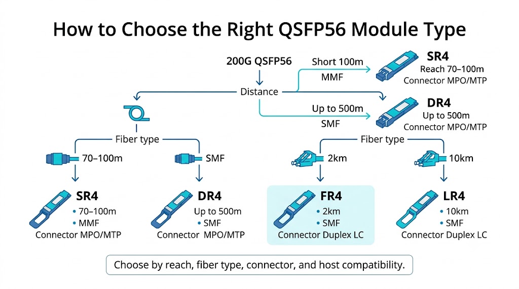
Selecting the correct QSFP56 module type comes down to four questions:
- 1. What is the required reach?Measure the actual fiber path, including slack and routing, not just the straight-line distance. Add margin for future moves.
- 2. What fiber is already installed?Reusing OM4 multimode fiber points to SR4. Single-mode fiber opens DR4, FR4, LR4, and ER4.
- 3. Does the switch support the module and FEC mode?Check the vendor-supported optics list and enable the correct FEC setting on both ends.
- 4. What is the power and thermal budget?High-density deployments with LR4 or ER4 modules need careful thermal validation.
A simple decision flow looks like this:
- •Distance under 100 m with OM4/OM5 → SR4(or LPO-SR4for AI clusters with compatible switches).
- •Distance 100–500 m or need 4×50G breakout → DR4.
- •Distance 500 m–2 km → FR4.
- •Distance 2–10 km → LR4.
- •Distance 10–40 km → ER4.
If the link is inside a cabinet and cost matters most, consider a passive DAC or AOC instead of a pluggable module.
QSFP56 Compatibility and Standards
Mechanical fit does not guarantee electrical compatibility. A QSFP56 module will physically insert into a QSFP28 cage, but it will not function unless the host ASIC supports 200GAUI-4 PAM4 signaling and the correct FEC mode.
Major switch vendors that support QSFP56 include Cisco, Arista, Juniper, NVIDIA/Mellanox, Dell, and Huawei. Each vendor maintains a supported optics list. Third-party MSA-compatible modules often work, but subtle firmware differences can affect DOM reporting or link training.
For procurement teams, the safest approach is to:
- •Confirm the exact switch model and software version.
- •Match the module part number to the vendor-supported list or use a tested MSA-compatible alternative.
- •Enable FEC consistently on both ends.
- •Document the fiber type, polarity, and cleaning standard used during installation.
Although QSFP28 and QSFP56 share the same mechanical form factor, the electrical interfaces differ significantly because QSFP56 uses PAM4 signaling instead of NRZ. For a detailed comparison of bandwidth, signaling, power consumption, and compatibility, see our QSFP28 vs QSFP56 guide.
Common QSFP56 Applications
QSFP56 module types appear in several high-growth deployment scenarios:
- •Hyperscale data centers: Spine-leaf upgrades from 100G to 200G using SR4 and DR4.
- •AI/ML clusters: GPU interconnects over InfiniBand HDR or 200GbE, often using SR4 or LPO-SR4.
- •High-performance computing: RDMA fabrics that require low latency and high message rates.
- •Enterprise core networks: Campus and aggregation links using FR4 or LR4.
- •Telecom backhaul: Long-distance aggregation using LR4 and ER4.
Conclusion
QSFP56 modules provide a flexible 200G connectivity portfolio spanning short-reach SR4, breakout-capable DR4, duplex-fiber FR4/LR4, extended-reach ER4, and emerging LPO options. Choosing the right module depends on transmission distance, installed fiber infrastructure, switch compatibility, and power budget. As AI clusters, cloud computing, and enterprise networks continue migrating toward higher bandwidth, understanding the strengths and limitations of each QSFP56 module type helps build scalable and cost-efficient optical networks.
Frequently Asked Questions
What is the most common QSFP56 module type?
200GBASE-SR4 is the most common because it covers most intra-data-center links and uses low-cost multimode fiber.
Can QSFP56 modules work in QSFP28 ports?
No. QSFP56 requires a host capable of 200GAUI-4 PAM4 signaling and FEC. A QSFP28 module will often work in a QSFP56-capable port, but not the reverse.
Is FEC required for all QSFP56 module types?
Yes. PAM4 signaling has a lower signal-to-noise margin than NRZ, so FEC is mandatory for reliable operation. The specific mode may vary by module and switch vendor.
What fiber do I need for QSFP56 SR4?
SR4 uses OM3, OM4, or OM5 multimode fiber with an MPO-12 connector. OM4 is the most common choice for new deployments.
When should I use LPO-SR4 instead of standard SR4?
Use LPO-SR4 when power and thermal budgets are tight, such as in large AI/ML clusters. Make sure your switch ASIC supports LPO operation.
How far can QSFP56 LR4 reach?
LR4 supports 10 km by default, and up to 20 km when FEC is enabled and the link budget allows it.
Can QSFP56 support InfiniBand?
HDR InfiniBand uses QSFP56 form factors but follows InfiniBand specifications rather than Ethernet standards.
Can QSFP56 connect directly to QSFP-DD?
No. Although they share some electrical concepts, QSFP-DD uses eight electrical lanes while QSFP56 uses four.
Post Views: 1,683