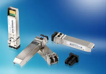
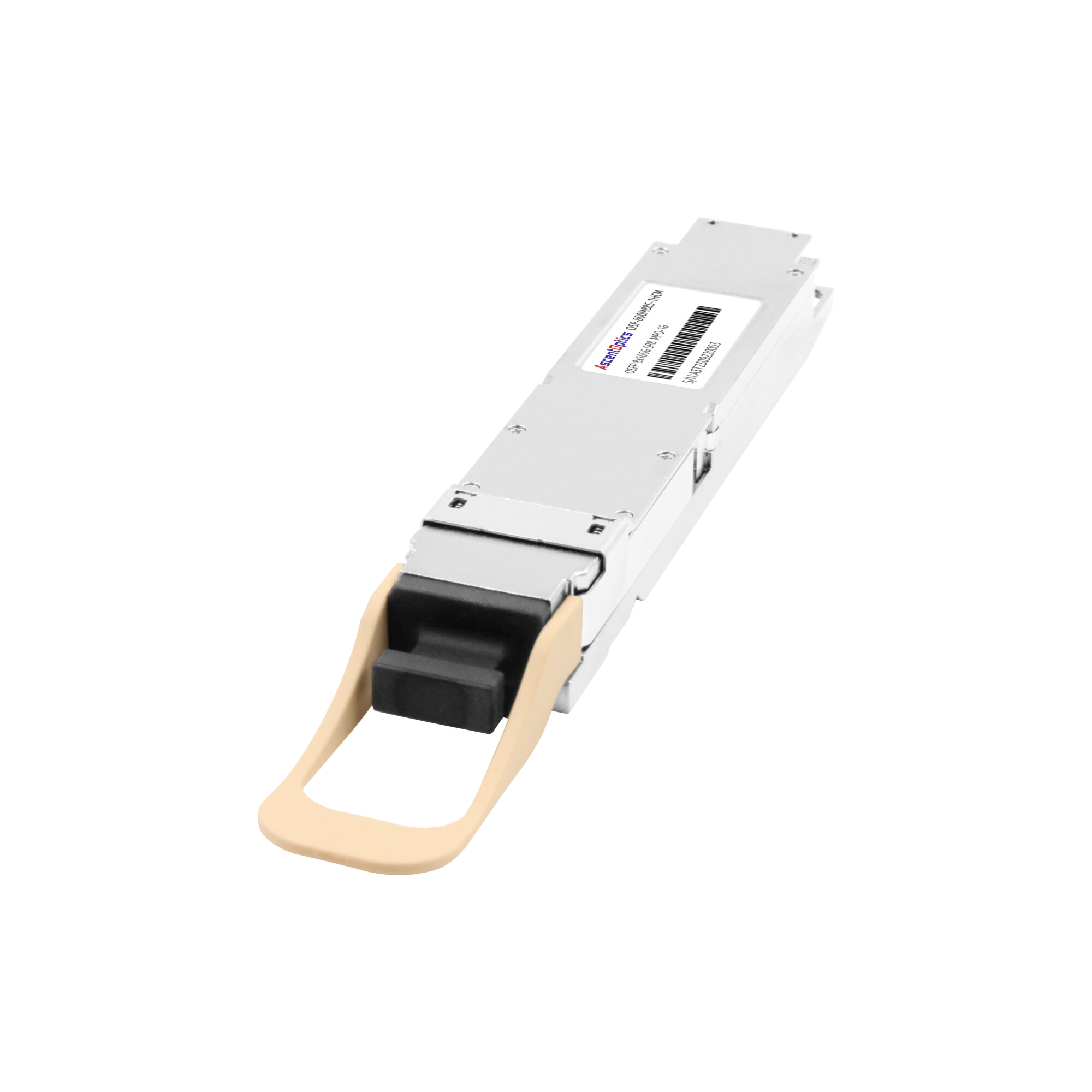
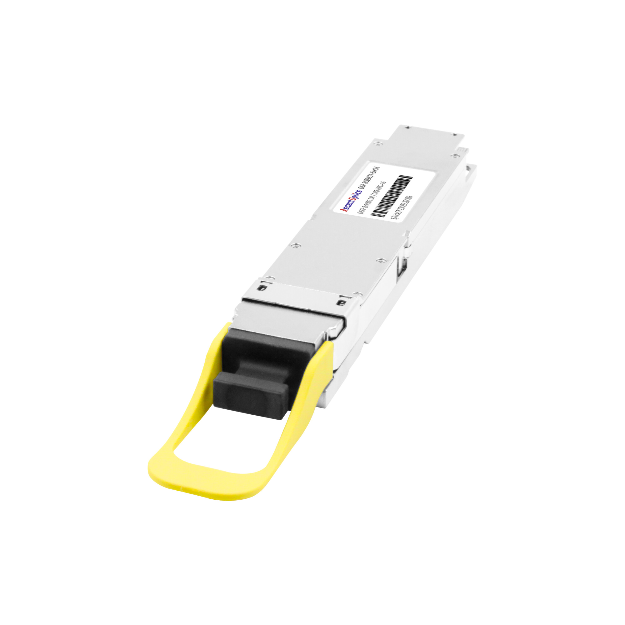
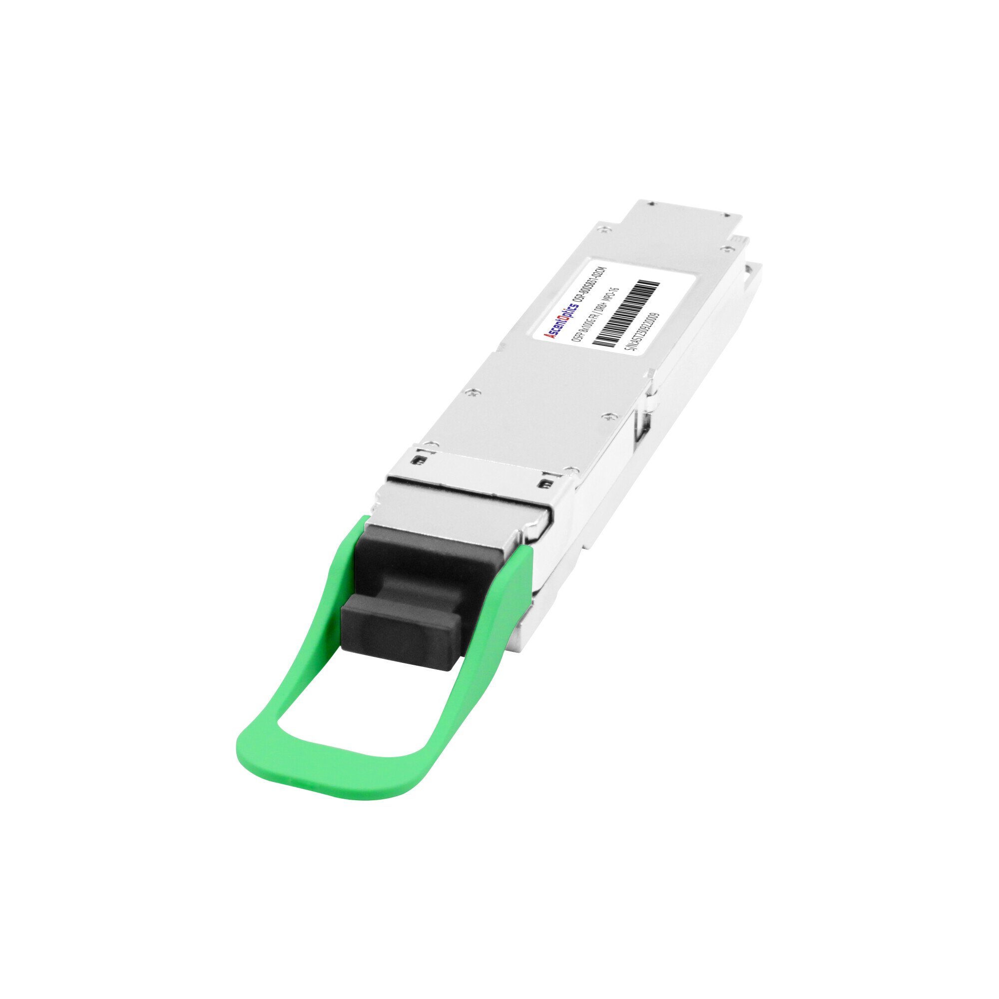
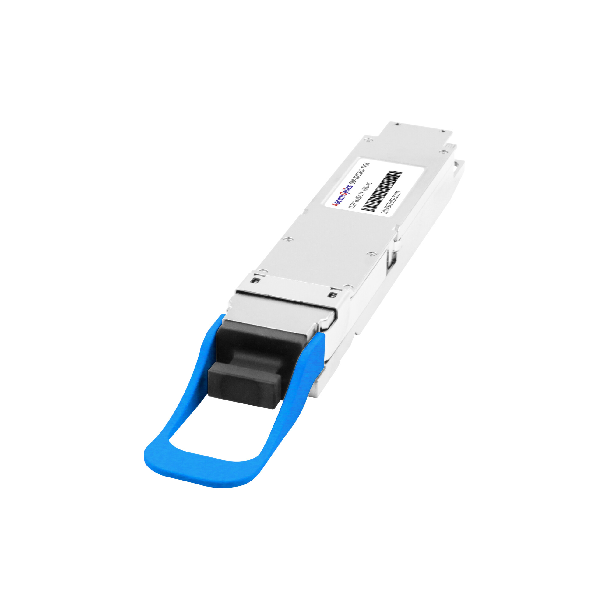
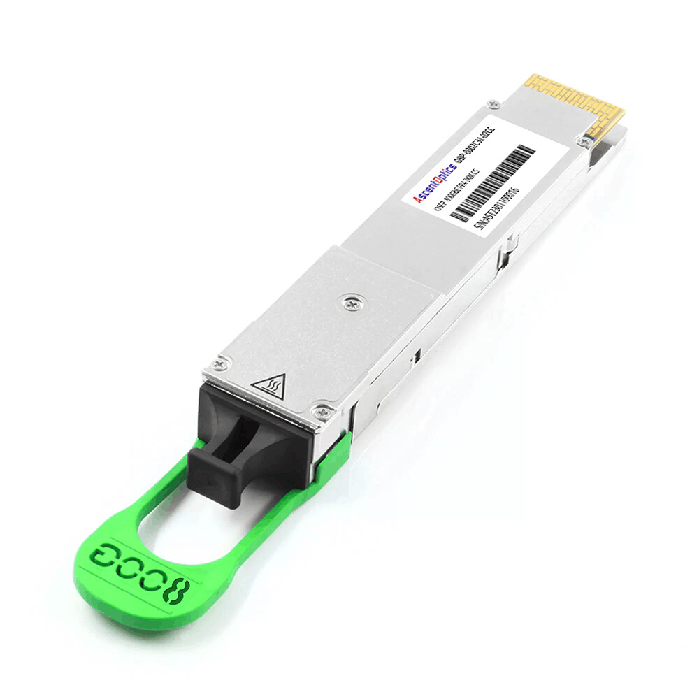
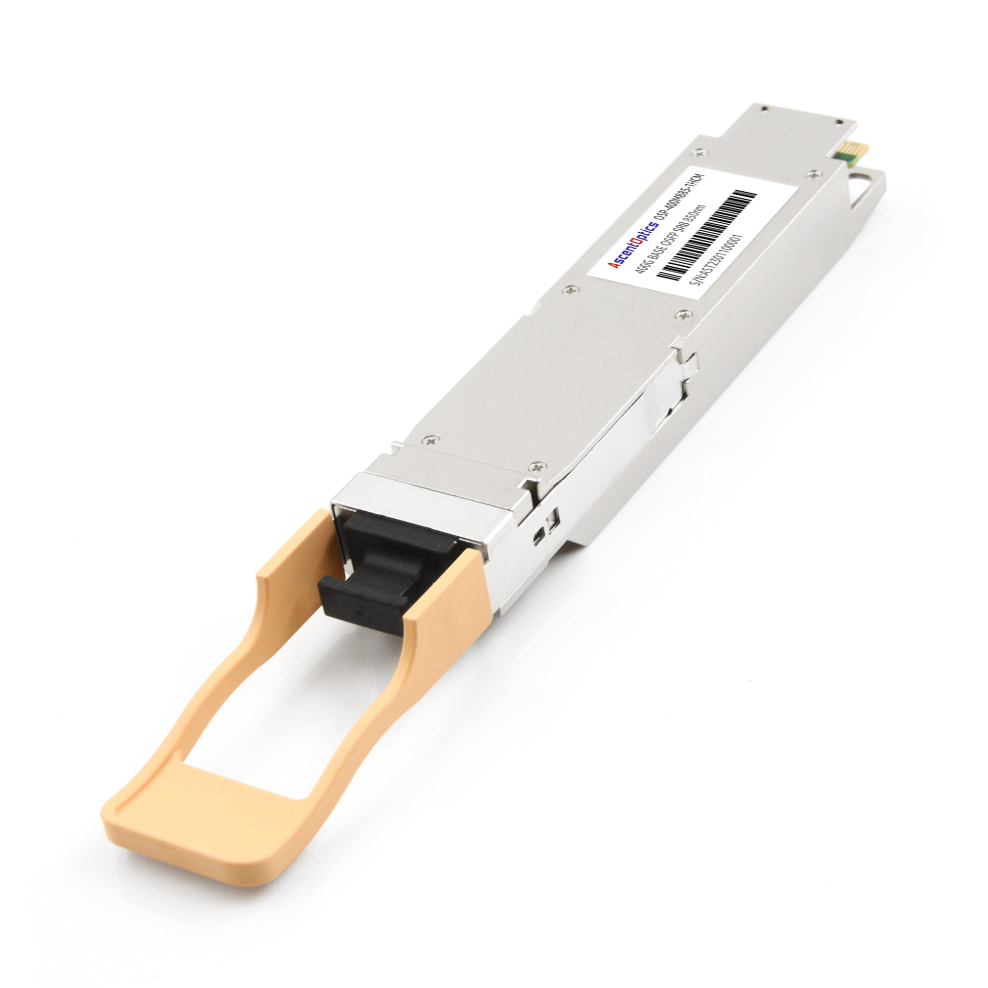
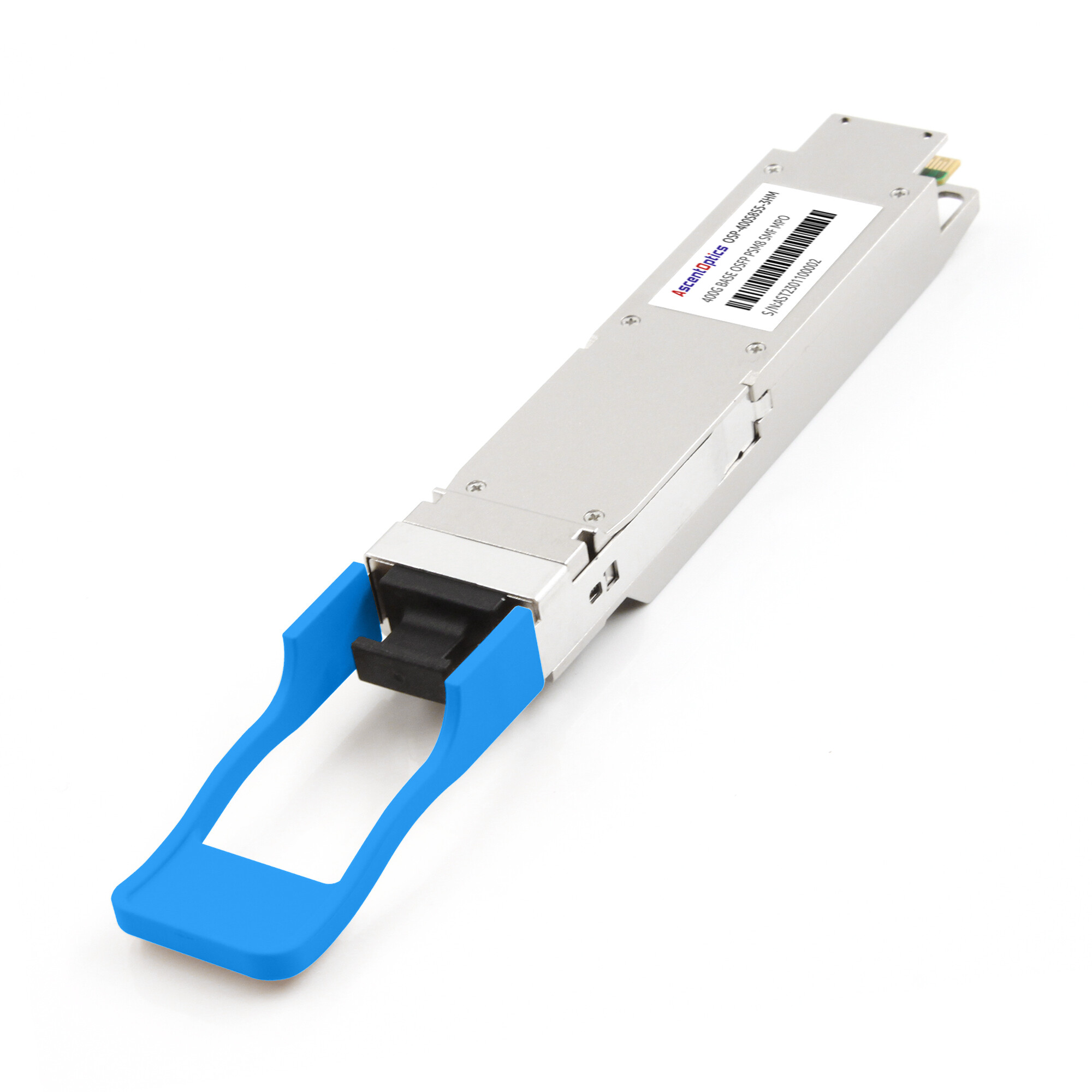
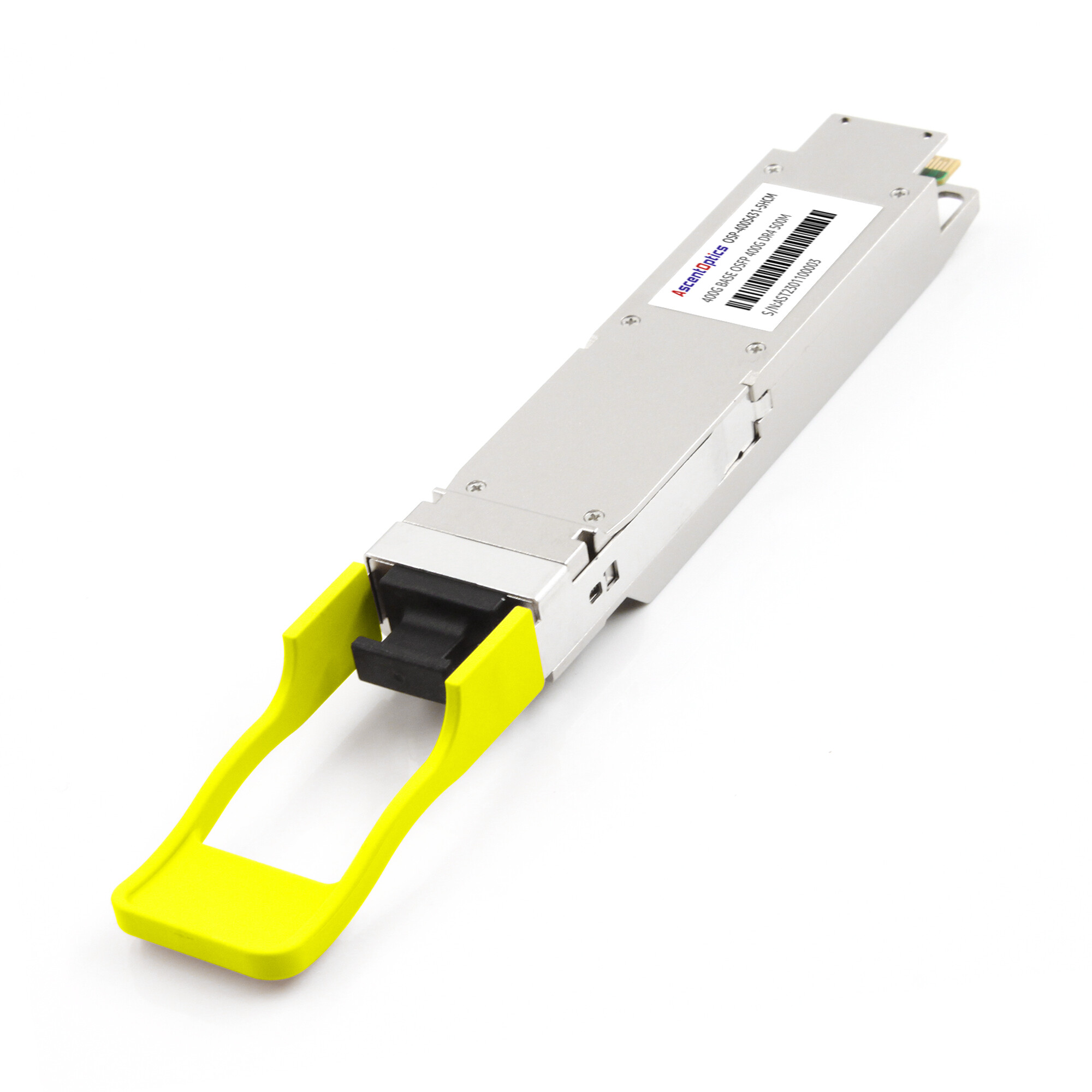
Most conventional 400G and 800G optical modules integrate a digital signal processor (DSP) to compensate for signal impairments and maintain reliable high-speed transmission. However, DSP is not an absolute requirement for every PAM4 optical link. Alternative architectures, such as Linear Pluggable Optics (LPO), move some signal-processing functions from the module to the host switch.
If you have worked with PAM4 at all, you already believe the shorthand: PAM4 “needs a DSP and FEC.” Most engineers stop there. The problem is that the shorthand hides the part that actually matters, which is why. Why does a modulation format force a processor into every module? What is that processor doing to your signal? And how does error correction turn a link that would drop one bit in ten thousand into one that effectively never drops a bit at all?
What Is a PAM4 DSP?
A PAM4 DSP is the digital signal processor inside a high-speed optical module that retimes, equalizes, and converts the lanes of a PAM4 signal so it can survive the trip from the switch to the laser and back.
Put differently, it is the component that makes 400G and 800G PAM4 physically possible. The module’s signal path runs from the electrical interface, into the DSP, then to the driver, laser or modulator, across the fiber, into a photodiode, through a TIA, and back into the DSP. The chip sits on both ends of that path for a reason.
The DSP does three jobs. First, it cleans up the received signal with equalization. Second, it converts lane counts and rates, a function called a gearbox. Third, it works with forward error correction to guarantee the link stays error-free. If you want the modulation fundamentals behind all of this, start with our complete guide to PAM4 modulation.
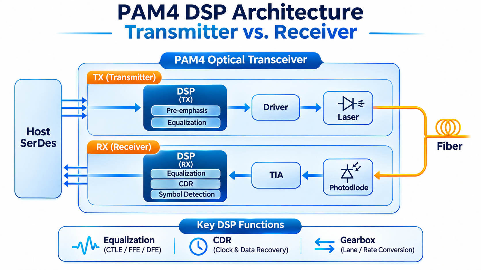
PAM4 DSP Architecture: Transmitter vs. Receiver
A PAM4 DSP performs different signal-processing tasks at the transmitter and receiver to maintain signal integrity.
On the transmit side, the DSP processes incoming electrical data and applies functions such as digital equalization and pre-emphasis to compensate for channel impairments. The processed signal is then sent to the driver and optical transmitter.
On the receive side, the DSP processes the electrical signal from the TIA and applies equalization to compensate for signal loss and inter-symbol interference (ISI). Depending on the architecture, it may also perform clock and data recovery (CDR) and symbol detection.
By coordinating these functions, the DSP helps ensure reliable PAM4 signal transmission.
Why PAM4 Needs a DSP: The ~9.5 dB SNR Penalty
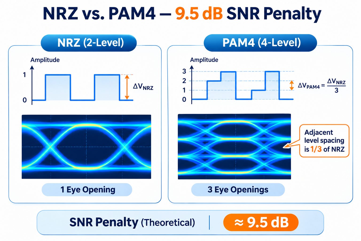
Here’s the root cause, and everything downstream follows from it. PAM4 crams four amplitude levels into the same voltage swing that older NRZ used for just two.
Four Levels, Three Small Eyes
With the same overall signal amplitude, PAM4 divides the voltage range into four levels, creating three smaller eye openings. The spacing between adjacent levels is approximately one-third that of an NRZ signal. This results in a theoretical SNR penalty of about 9.5 dB under comparable conditions, making PAM4 more sensitive to noise, crosstalk, and inter-symbol interference (ISI).
Nine and a half decibels is not a rounding error. It means a PAM4 signal is far more sensitive to anything that disturbs those tight level spacings. Noise, inter-symbol interference, crosstalk, and reflections all have an easier time flipping a level when the levels are a third as tall.
From “Optional” at 100G to “Mandatory” at 400G
This is why the DSP went from a nice-to-have to a requirement as speeds climbed. At 100G, NRZ lanes running 25 Gbps could get by without heavy signal processing. When the industry moved to 100 Gbps per lane using PAM4, that margin evaporated.
The Equalization Chain: CTLE, FFE, and DFE
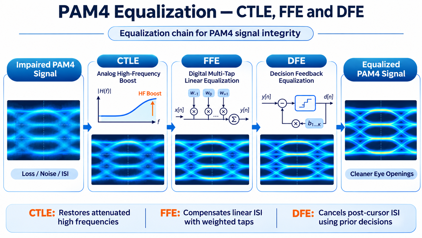
So what does the DSP actually do to a degraded PAM4 signal? It runs it through a sequence of equalizers, each attacking a different part of the problem. Understanding the chain is the difference between seeing the DSP as a black box and seeing it as an engineering instrument.
CTLE: The Analog Front-End Boost
The first stage is the continuous-time linear equalizer, or CTLE. It is an analog circuit that boosts the high frequencies that the channel attenuated. Think of it as a treble control that restores the sharp edges a long trace or connector rounded off.
CTLE is fast and simple, but it is coarse. It cannot correct the more complex, symbol-to-symbol interference that high-speed channels produce. That is where the digital stages come in.
FFE: Feed-Forward Equalization in the Digital Domain
A feed-forward equalizer (FFE) is a linear filter that uses multiple weighted taps to compensate for inter-symbol interference (ISI). Depending on the system architecture, FFE can be implemented at the transmitter, receiver, or both ends of a high-speed link. It counteracts the predictable spread of energy from one symbol into the next.
FFE is good at undoing the linear, causal part of the channel. But it has a limitation: it cannot perfectly remove interference from symbols that have already been decided, especially as baud rates climb.
DFE: Decision Feedback for Higher Baud Rates
That is the job of the decision feedback equalizer, or DFE. Once the receiver has decided on a symbol, the DFE feeds that decision back to cancel the interference it would cause in the next symbols. Because it works on decided symbols, it can cancel interference without amplifying noise the way a linear filter would.
At high baud rates, such as 53.125 GBaud and beyond, DFE can play an important role in compensating for post-cursor ISI. Its implementation depends on channel characteristics and the receiver’s equalization architecture. The three stages work as a team: CTLE restores amplitude, FFE untangles the linear channel, and DFE cleans up the leftover interference using prior decisions.
The Transmit Side: Pre-Emphasis and Digital Pre-Distortion
Equalization is not only a receive-side affair. On the transmit side, the DSP applies pre-emphasis to boost the signal before it hits the channel. In some advanced transmitter designs, digital pre-distortion (DPD) may also be used to compensate for nonlinearities in the optical transmitter, helping improve signal quality before transmission over the fiber.
Here’s the chain at a glance:
| Stage |
Domain |
What it does |
| CTLE |
Analog |
Boosts the high frequencies the channel attenuated |
| FFE |
Digital |
Multi-tap filter that undoes linear inter-symbol interference |
| DFE |
Digital |
Cancels interference from already-decided symbols |
| Pre-emphasis / DPD |
Transmit |
Boosts the signal and corrects laser nonlinearity before the fiber |
If you want to see how all of this shows up on a scope, our PAM4 eye diagram and signal integrity guide walks through the before-and-after.
Why Equalization Alone Is Not Enough: FEC
Here’s the uncomfortable truth the equalization chain can’t get around. Even a well-tuned DSP leaves a PAM4 link with a raw bit error rate around 1E-4 to 1E-5. That is one error in every ten thousand bits, which is nowhere near good enough for a production network.
Pre-FEC vs Post-FEC BER: The 1E-4 to 1E-15 Leap
Even after DSP-based equalization, a high-speed PAM4 link may still contain residual bit errors. The actual pre-FEC BER depends on the optical link conditions and receiver performance.
Forward Error Correction (FEC) adds redundant information to the transmitted data, allowing the receiver to detect and correct errors without retransmission. When the pre-FEC BER remains within the correction capability of the selected FEC scheme, the post-FEC BER can be reduced dramatically, potentially reaching levels such as 1E-12 or lower, depending on the system requirements and implementation.
KP4 FEC: The 400G/800G Workhorse
KP4 FEC uses the RS(544,514) Reed-Solomon code, which adds 30 parity symbols to every 514 information symbols. This results in an FEC coding overhead of approximately 5.84%.
For 100G-per-lane PAM4 transmission, the nominal electrical or optical lane rate is commonly 106.25 Gbps, while the corresponding Ethernet data rate is 100 Gbps. The difference accounts for FEC and other PCS-related overheads.
The DSP as a Gearbox: Converting Lane Rates
Equalization and FEC are only two of the DSP’s jobs. It also does something more mundane but equally important: it translates lane counts.
A 400G QSFP-DD switch interface presents eight 50G PAM4 electrical lanes. A 400G DR4 module needs four 100G PAM4 optical lanes. Something has to repackage eight lanes into four. That something is a gearbox function inside the DSP.
This is the quiet reason the DSP is hard to remove entirely. An LPO module that deletes the DSP also deletes the gearbox, which means it only works where the electrical and optical lane rates already match. That constraint is the entire story behind LPO’s short reach and compatibility limits, and we cover it in depth in our 800G LPO guide.
DSP vs. Retimer vs. Gearbox: What’s the Difference?
DSP, retimer, and gearbox are related technologies in high-speed communication systems, but they serve different purposes.
| Technology |
Primary Function |
| DSP |
Performs signal processing and equalization |
| Retimer |
Recovers clock timing and regenerates data |
| Gearbox |
Converts between different lane configurations or data rates |
A DSP may integrate retiming and gearbox functions into a single chip, but these terms are not interchangeable. Each plays a different role in maintaining signal integrity and supporting high-speed data transmission.
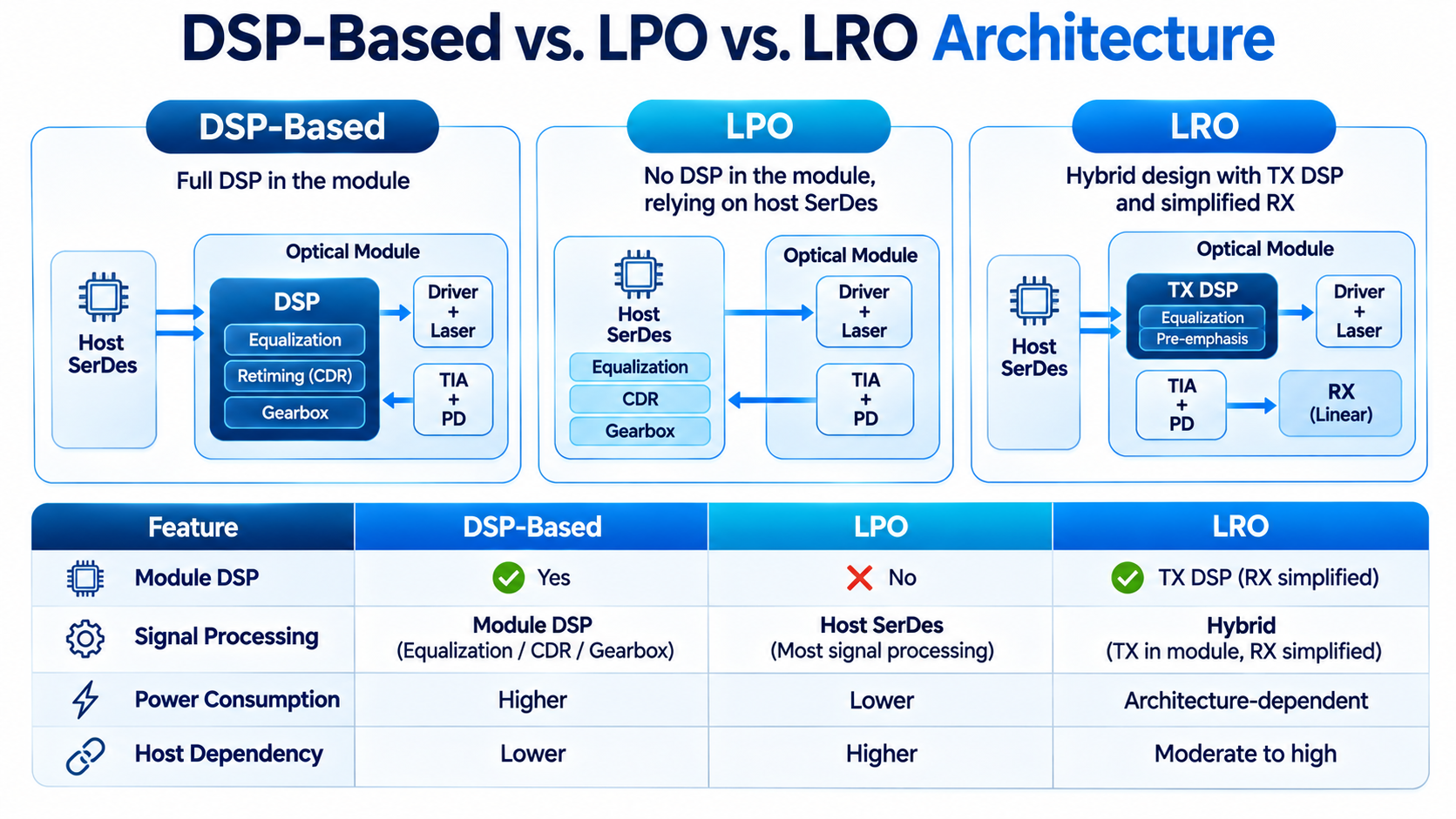
DSP-Based Modules vs. LPO vs. LRO
As data rates increase, optical transceiver architectures are evolving to balance power consumption, latency, and signal integrity. DSP-based modules, Linear Pluggable Optics (LPO), and Linear Receive Optics (LRO) represent three different approaches.
Traditional DSP-based modules integrate a DSP to perform signal conditioning, equalization, and retiming. This provides greater flexibility but increases power consumption and latency.
LPO removes the module DSP and relies more heavily on the host switch’s SerDes for signal conditioning. This reduces module power consumption and latency but places greater demands on host SerDes performance and electrical channel quality.
LRO adopts a hybrid approach, typically retaining transmit-side DSP processing while simplifying the receive-side signal-processing architecture.
| Feature |
DSP-Based |
LPO |
LRO |
| Module DSP |
Yes |
No |
Typically TX DSP |
| Signal processing |
Module DSP |
Host SerDes |
Hybrid |
| Power consumption |
Higher |
Lower |
Architecture-dependent |
| Host dependency |
Lower |
Higher |
Moderate to high |
The choice depends on transmission distance, host SerDes capability, power budget, and overall link requirements.
PAM4 DSP in 400G and 800G Optical Transceivers
PAM4 DSP technology plays an important role in modern 400G and 800G optical transceivers. As Ethernet speeds increase, higher per-lane data rates place greater demands on electrical signal integrity and optical transmission performance.
In 400G and 800G optical modules, PAM4 enables higher data rates per lane without requiring a proportional increase in the number of physical channels.
PAM4 in 400G Optical Transceivers
400G optical transceivers commonly use four or eight optical lanes, depending on the interface design.
For example:
– 400G DR4: Uses four 100G-class PAM4 optical lanes over parallel single-mode fiber.
– 400G FR4: Uses four optical wavelengths, each carrying approximately 100G, over duplex single-mode fiber.
– 400G SR4: Uses four 100G-class PAM4 optical lanes over parallel multimode fiber.
PAM4 in 800G Optical Transceivers
800G optical transceivers further increase bandwidth by using eight 100G-class lanes or alternative lane configurations.
Common examples include:
– 800G DR8: Uses eight 100G-class PAM4 optical lanes over parallel single-mode fiber.
– 800G 2×FR4: Uses two groups of four optical wavelengths, with each wavelength carrying approximately 100G.
– 800G SR8: Uses eight 100G-class PAM4 optical lanes over parallel multimode fiber.
In these applications, DSP-based signal processing helps compensate for electrical channel impairments, improve signal quality, and support reliable high-speed transmission.
The specific DSP architecture depends on the optical interface, host electrical interface, lane configuration, and transmission requirements.
Frequently Asked Questions
Why does PAM4 need a DSP?
PAM4 uses four amplitude levels instead of NRZ’s two, which imposes about a 9.5 dB signal-to-noise penalty. A DSP restores the resulting signal degradation through equalization and enables the FEC and gearbox functions that make high-speed links usable.
Why does PAM4 need forward error correction?
Even after DSP equalization, a PAM4 link runs a raw bit error rate around 1E-4. FEC corrects this to roughly 1E-15 post-FEC, which is essential for a production network.
What is the difference between pre-FEC and post-FEC BER?
Pre-FEC BER is the error rate before correction, typically 1E-4 to 1E-5 on PAM4. Post-FEC BER is the rate after correction, typically 1E-15. The post-FEC number is what determines whether a link is healthy.
What is KP4 FEC?
KP4 is a Reed-Solomon forward error correction code, RS(544,514), standardized in IEEE 802.3bs. It is the default FEC for 400G and 800G Ethernet and adds roughly seven percent overhead.
What does a PAM4 DSP do besides equalization?
It also performs lane-rate conversion, called a gearbox, and provides link diagnostics such as per-lane pre-FEC BER and SNR reporting.
Post Views: 121