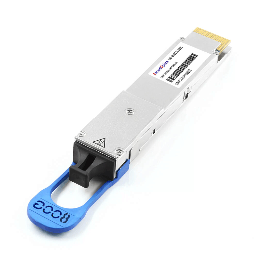
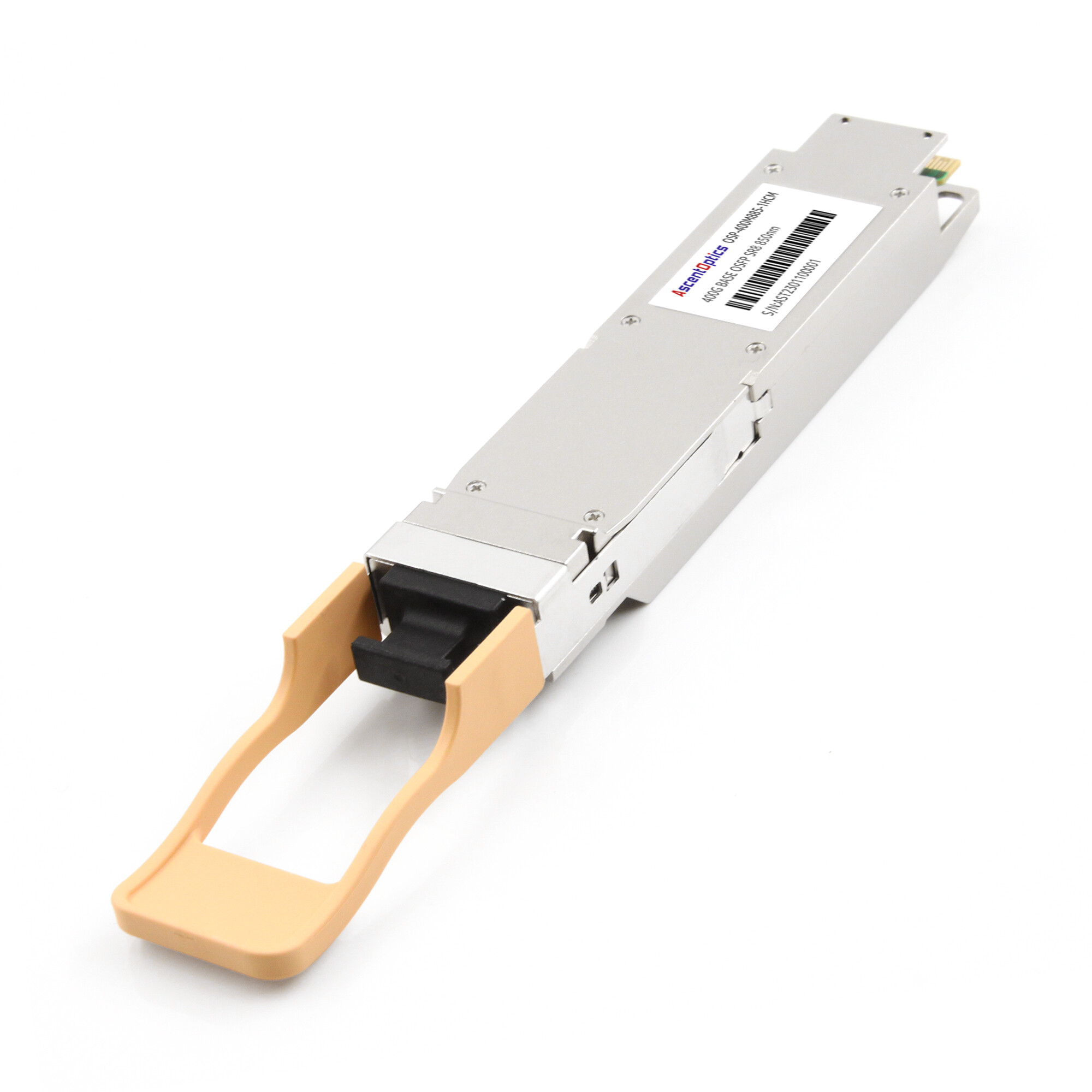
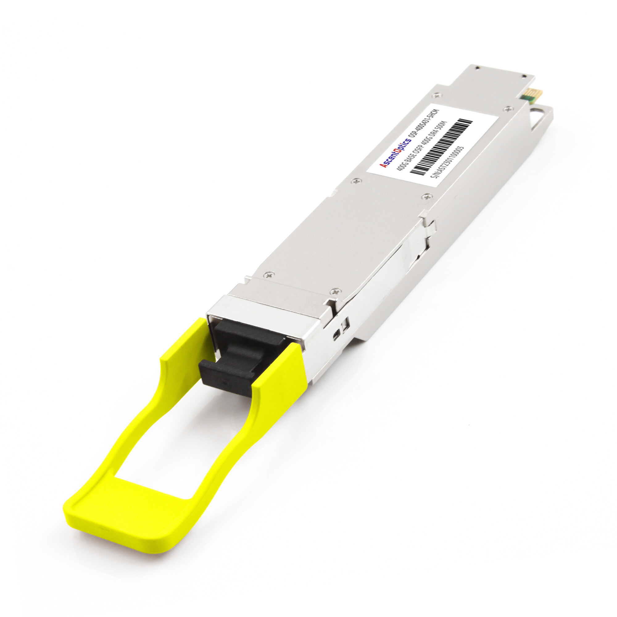
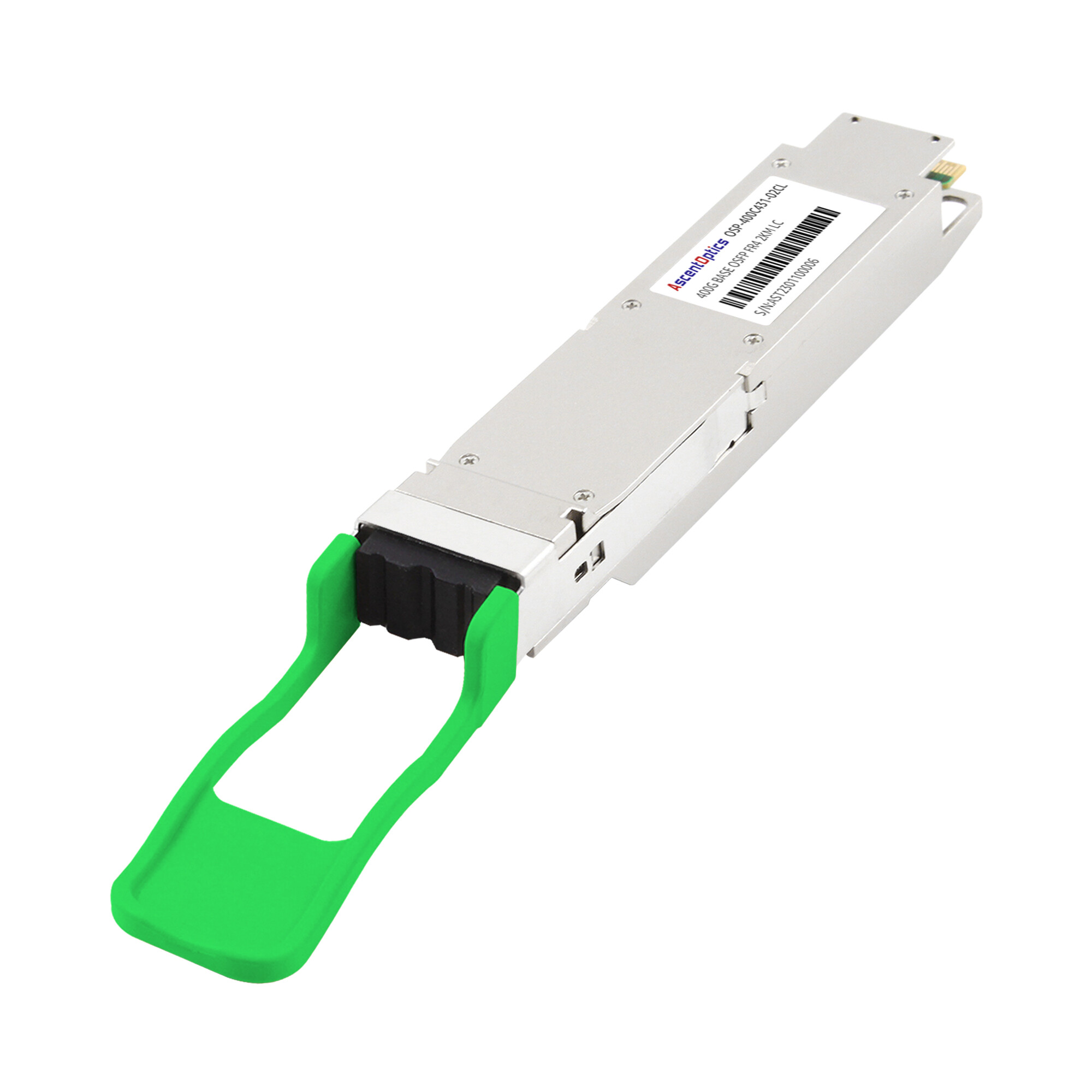
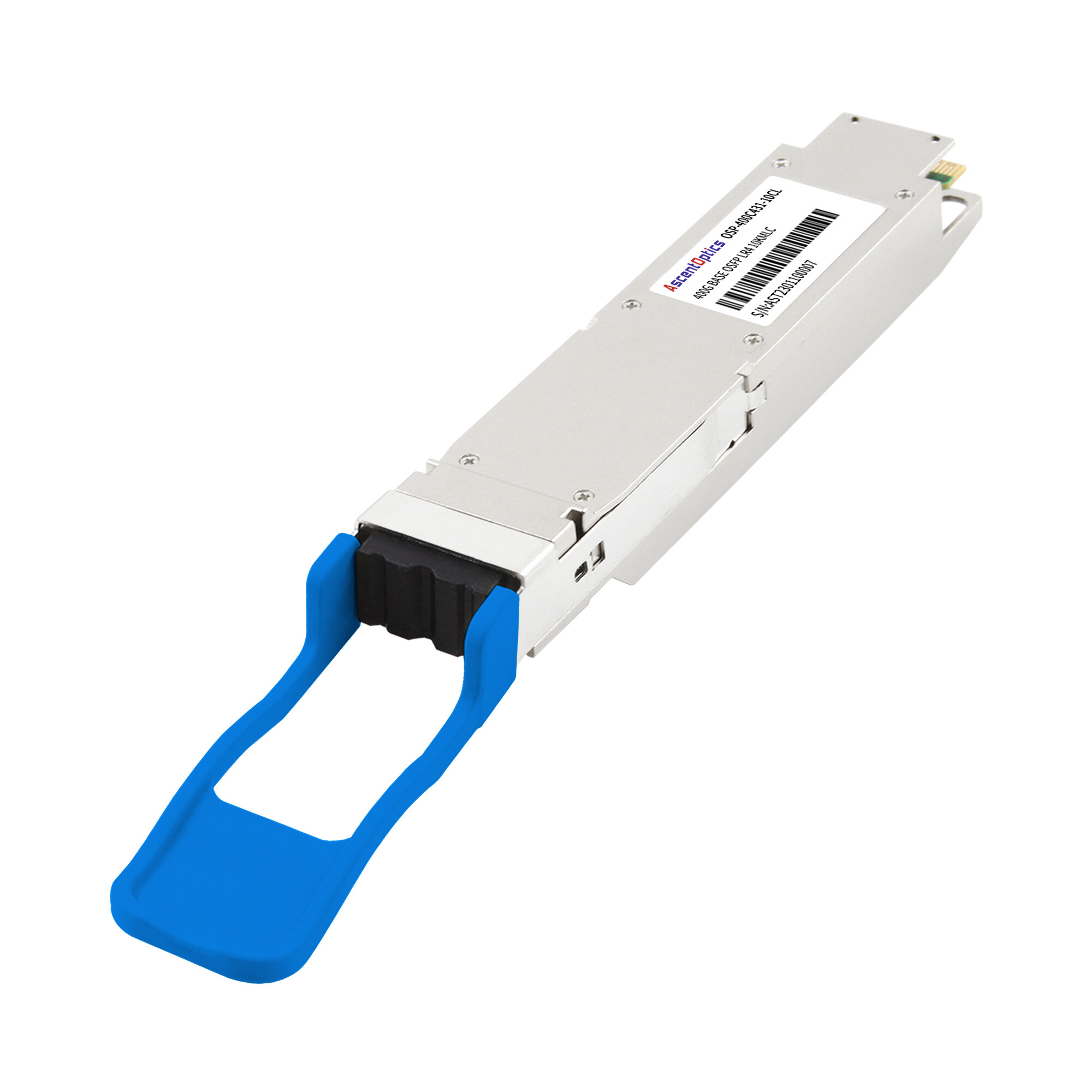
When a data center engineer first handles an 800G OSFP module, the physical impression is immediate and unmistakable. The module is larger than the QSFP28 transceivers that dominated racks for the past decade. It carries a built-in aluminum heat sink that adds visible bulk. And it consumes enough power that touching it during operation would be genuinely uncomfortable.
This is not a design oversight. It is the entire point.
The OSFP form factor was engineered specifically to solve the thermal and electrical challenges that older form factors could not address at 400G, 800G, and beyond. Network architects choosing optical transceivers for next-generation data centers need to understand what OSFP offers, how it differs from alternatives, and when it is the right choice for their infrastructure. This guide covers the physical specifications, electrical architecture, thermal design, module types, and deployment considerations that define the OSFP form factor.
What Is the OSFP Form Factor?
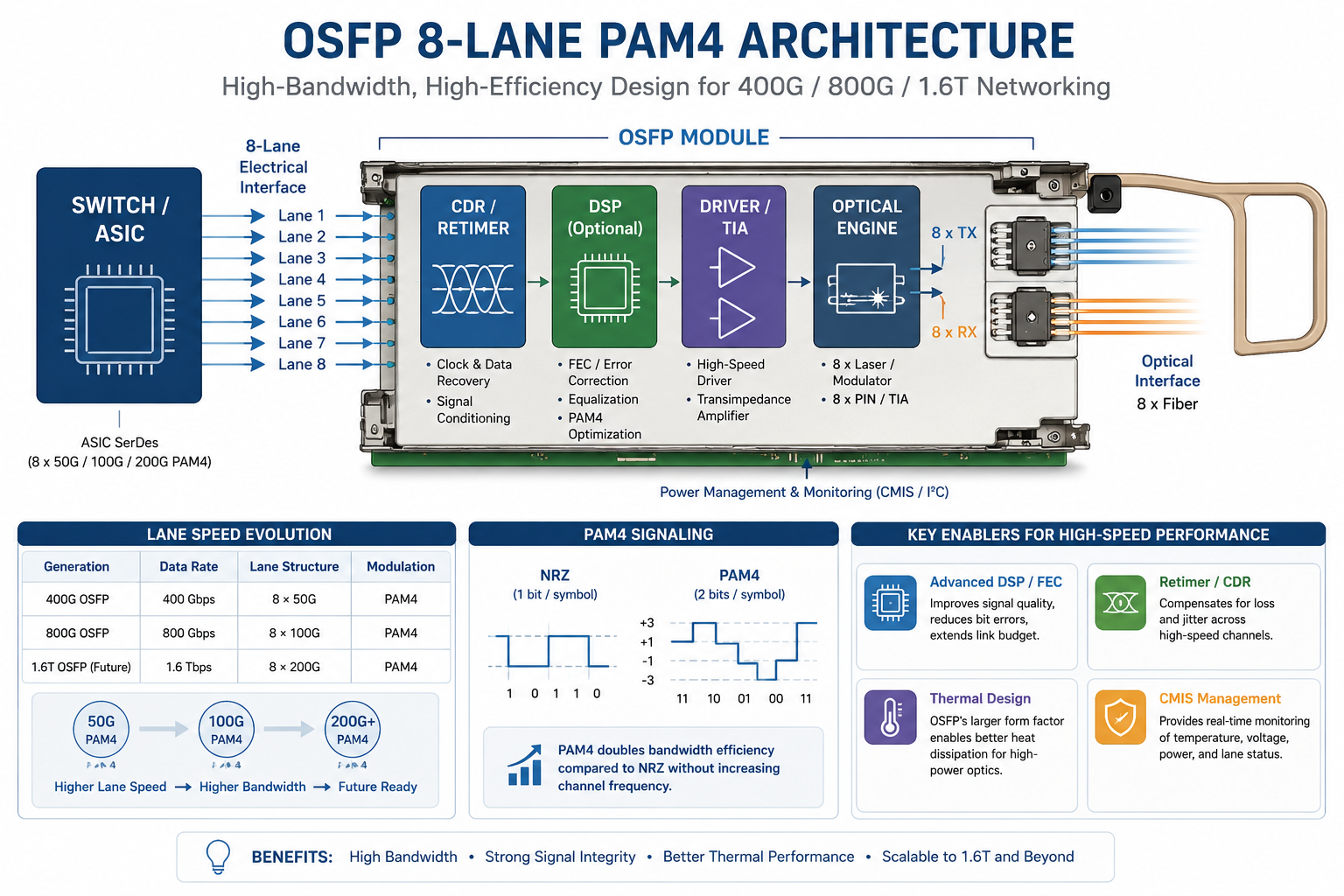
OSFP stands for Octal Small Form-factor Pluggable. The “octal” designation refers to the eight electrical lanes that carry data between the module and the host switch. Each lane operates at 50 Gbps or 100 Gbps using PAM4 signaling, enabling aggregate data transmission rates of 400 Gbps, 800 Gbps, or 1.6 Tbps depending on the module generation.
The OSFP Multi-Source Agreement (MSA) consortium, founded by Google and led by Arista Networks, developed this form factor to address the limitations of existing standards as data centers transitioned beyond 100G. The MSA released the initial OSFP specification in 2018, with subsequent revisions adding support for higher speeds and thermal variants. The current OSFP MSA Revision 5.22, published in August 2025, defines the complete electrical, mechanical, and management interface requirements for 400G, 800G, and early 1.6T implementations.
Unlike previous form factors that evolved incrementally from earlier designs, OSFP represents a clean-sheet approach. The 60-pin edge connector, integrated heat sink, and management interface are entirely new. There is no backward compatibility with QSFP, QSFP28, or QSFP-DD modules. This design decision eliminated the engineering compromises that backward compatibility typically imposes.
Last year, Marcus Chen led the network architecture team at a financial services firm preparing to upgrade their trading floor infrastructure to 400G. When evaluating the OSFP form factor against QSFP-DD, the density numbers initially favored the smaller QSFP-DD option. His team could fit 36 QSFP-DD ports per 1U switch versus 32 OSFP ports. But Marcus studied the thermal specifications more carefully. Each 400G ZR coherent module would draw approximately 18W. In a fully populated 32-port switch, that meant 576W of heat from optical modules alone. The OSFP form factor’s integrated heat sink provided the thermal margin his cooling budget required. The firm standardized on OSFP, and during the first summer heat wave after deployment, the thermal monitoring system confirmed what the specifications had promised: zero thermal-related failures across the entire fleet.
The OSFP form factor occupies a specific position in the evolution of optical transceiver standards. SFP modules addressed 1G needs. SFP+ handled 10G. QSFP+ and QSFP28 covered 40G and 100G respectively. QSFP-DD extended the QSFP family to 400G through double-density pin arrangements. OSFP breaks from this lineage entirely, offering a purpose-built platform for 400G through 1.6T and beyond.
If you are evaluating 400G OSFP transceiver types for an upcoming deployment, understanding the underlying form factor architecture helps you select the right module for your network requirements.
OSFP Physical Specifications and Dimensions
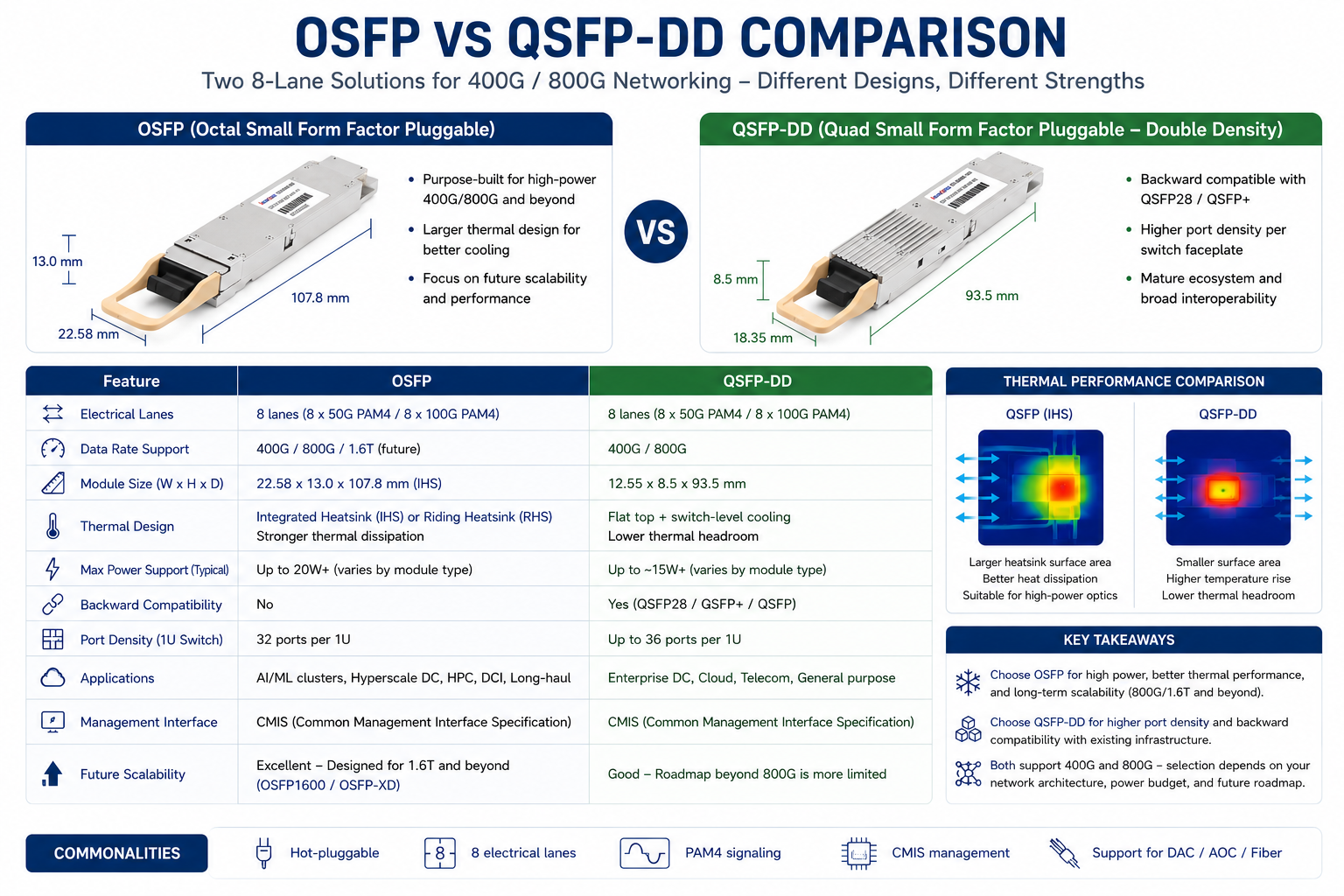
Understanding the OSFP form factor begins with its physical dimensions. The standard OSFP module measures 22.58 mm in width, 107.8 mm in depth, and 13.0 mm in height for the Integrated Heat Sink (IHS) variant. These dimensions make OSFP approximately 23% wider than QSFP-DD and roughly 53% taller.
The larger physical envelope serves a specific engineering purpose. At 800G and above, optical transceiver modules generate significant heat. DSP chips, laser drivers, and optical components all contribute to thermal load. The OSFP housing provides approximately twice the volume of QSFP-DD, creating space for larger heat sinks, better airflow paths, and more robust thermal management.
The 60-pin edge connector represents another departure from legacy designs. QSFP-DD uses a stacked cage approach that adds rows of pins to the existing QSFP connector. OSFP replaces this entirely with a single-row 60-pin edge connector. The pin assignments include 16 high-speed differential pairs for data, 16 clock signals, 4 control signals, 4 power pins, and 20 ground pins. This simplified pinout improves signal integrity at the higher data rates OSFP targets.
Port density remains a practical consideration for network architects. A typical 1U switch accommodates 32 OSFP ports or up to 36 QSFP-DD ports. This difference matters in environments where every rack unit carries significant cost. However, many data center architects now prioritize thermal stability over maximum density, particularly in AI and high-performance computing clusters where sustained high loads are the norm rather than the exception.
OSFP Electrical Interface and Architecture
The electrical foundation of the OSFP form factor is its eight-lane architecture. Each lane consists of a transmit and receive differential pair, creating 16 high-speed electrical signals in total. For 400G modules, each lane carries 50 Gbps using PAM4 modulation, yielding 8 x 50 Gbps = 400 Gbps aggregate. For 800G modules, each lane carries 100 Gbps using PAM4, yielding 8 x 100 Gbps = 800 Gbps.
PAM4 (Pulse Amplitude Modulation with 4 levels) enables higher data rates without proportionally increasing the electrical signaling frequency. Traditional NRZ (Non-Return-to-Zero) encoding uses two voltage levels to represent one bit per symbol. PAM4 uses four voltage levels to represent two bits per symbol, effectively doubling the data rate at the same baud rate. This efficiency is essential for maintaining signal integrity across the 60-pin connector and through the module’s internal traces.
The electrical interface follows IEEE 802.3ck for 100 Gb/s per lane signaling and IEEE 802.3df for 800 Gb/s Ethernet. The OSFP MSA defines the mechanical and electrical requirements that complement these IEEE standards, ensuring interoperability between modules from different manufacturers.
Management of OSFP modules occurs through the Common Management Interface Specification (CMIS). CMIS 5.0 and later revisions define the register map, monitoring parameters, and control functions for OSFP modules. This management interface provides real-time access to critical operational data including temperature, transmit and receive optical power, laser bias current, and supply voltage. Digital Diagnostics Monitoring (DDM) functions exposed through CMIS allow network management systems to track module health and predict potential failures before they impact network performance.
The CMIS implementation in OSFP also supports advanced features that earlier management interfaces could not accommodate. These include dynamic power management, which allows modules to reduce power consumption during idle periods, and thermal shutdown protection, which prevents module damage when operating temperatures exceed safe thresholds.
OSFP Thermal Design: IHS vs RHS
Thermal management distinguishes the OSFP form factor more than any other characteristic. As optical modules have advanced from 100G to 800G and toward 1.6T, power consumption has increased proportionally. A typical 400G SR8 module might draw 10-12W. An 800G DR8 module can consume 15-18W. Coherent modules for long-haul applications may exceed 25W. In a 32-port switch populated with high-power modules, total optical power dissipation can approach 800W.
OSFP addresses this challenge through two primary thermal variants.
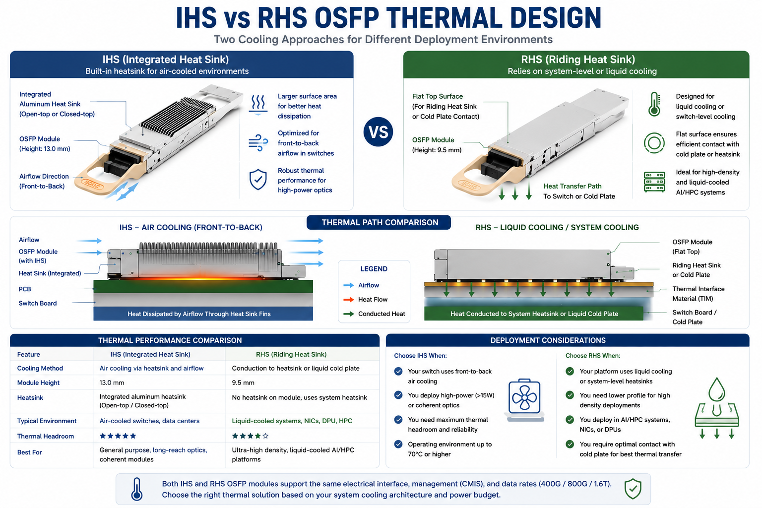
Integrated Heat Sink (IHS)
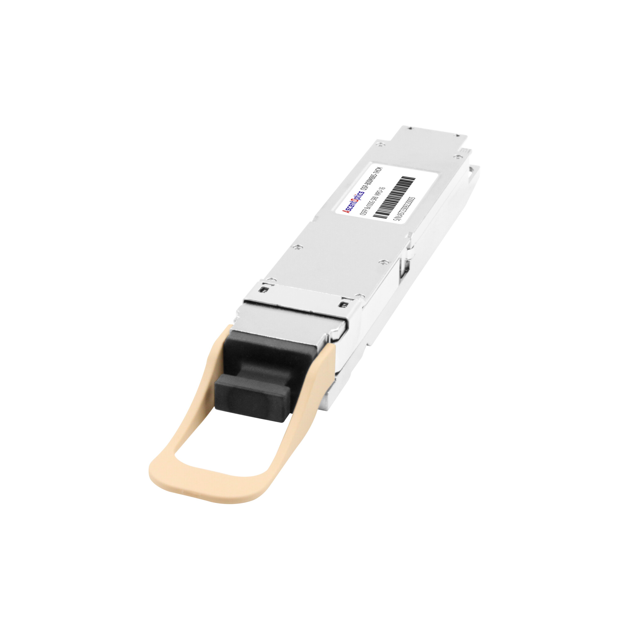
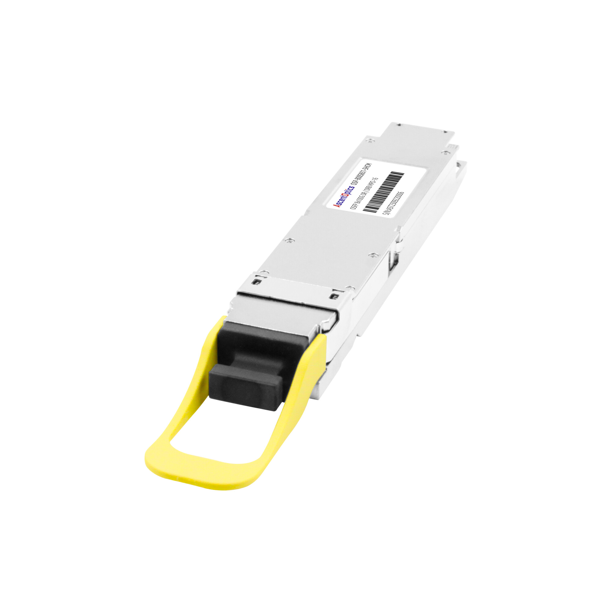
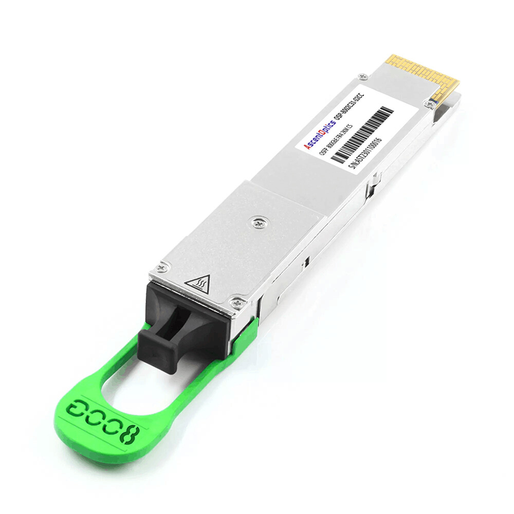
The standard OSFP-IHS variant features a built-in aluminum heat sink integrated into the module housing. The IHS design comes in two configurations: open-top, which exposes the heat sink fins for direct airflow contact, and closed-top, which provides a protected surface while still enabling thermal transfer. The IHS variant measures 13.0 mm in height and is designed for switches with front-to-back airflow patterns.
The integrated heat sink design increases the module’s surface area by approximately 30% compared to flat-top alternatives. This additional surface area enables more efficient heat transfer to the surrounding air. The OSFP MSA specifies standard operating temperatures of 0℃ to 70℃ for most module types, with some extended-range variants supporting up to 75℃ or 80℃.
Riding Heat Sink (RHS)
The OSFP-RHS variant uses a flat-top design measuring 9.5 mm in height. Instead of an integrated heat sink, the RHS module relies on a riding heat sink mechanism within the switch cage itself. This design is particularly suited for network interface cards (NICs), DPUs, and systems where liquid cooling is employed.
The flat surface of the RHS module is ideal for contact with cold plates in liquid-cooled data centers. As AI clusters and high-performance computing environments increasingly adopt liquid cooling to manage GPU and switch thermal loads, the RHS variant provides a direct thermal path without the fin geometry that would interfere with cold plate contact.
Power Envelope and Thermal Limits
The OSFP MSA defines a standard power envelope of up to 15W for most applications. Extended power classes support modules drawing up to 20W or more. The maximum insertion force is specified at 40N for standard cages and 55N for RHS cages. Maximum extraction force is 30N for standard and 45N for RHS configurations.
These mechanical specifications matter during installation and maintenance. Network technicians working in dense environments need to understand the physical requirements for inserting and removing modules without damaging connectors or cages. The higher extraction force for RHS modules reflects the tighter mechanical tolerances required for reliable thermal contact.
OSFP Module Types by Speed and Application
The OSFP form factor supports multiple data rates and reach configurations, making it adaptable to diverse network architectures.
400G OSFP was the first generation to reach commercial deployment. Common variants include:
- •SR8: Up to 100 meters over multimode fiber using eight parallel lanes, ideal for intra-rack and intra-cluster connections
- •DR4: Up to 500 meters over single-mode fiber, suitable for leaf-spine interconnects within a data center
- •FR4: Up to 2 kilometers over single-mode fiber using CWDM multiplexing, for campus and metro distances
- •LR4: Up to 10 kilometers over single-mode fiber, for data center interconnect and metro applications
- •ZR/ZR+: Up to 80 kilometers or more using coherent optics, for long-haul and regional connectivity
800G OSFP modules represent the current mainstream deployment standard for hyperscale and AI data centers:
- •SR8: Up to 100 meters over multimode fiber
- •DR8: Up to 500 meters over single-mode fiber
- •2FR4: Dual 400G FR4 in a single module, enabling 2x400G breakout
- • 2LR4: Dual 400G LR4 for longer-reach 800G applications
The breakout capability of 800G OSFP modules provides significant deployment flexibility. An 800G port can often operate as two 400G channels or four 200G channels, allowing network operators to adapt their connectivity as bandwidth requirements evolve.
The next generation extends beyond standard OSFP. OSFP1600 modules maintain the same 22.58 mm width as standard OSFP but support 8 x 200G PAM4 signaling for 1.6 Tbps aggregate bandwidth. These modules remain backward compatible with 800G OSFP cages, protecting infrastructure investments.
OSFP-XD (eXtended Density) takes a different approach. At 28.15 mm wide, OSFP-XD accommodates 16 electrical lanes of 100G PAM4, also achieving 1.6 Tbps. However, the increased width means OSFP-XD modules are not backward compatible with standard OSFP cages. Network architects planning for 1.6T must choose between OSFP1600’s compatibility and OSFP-XD’s density advantages.
For a complete overview of available module configurations, see our guide to 800G OSFP transceivers and their deployment applications.
OSFP Connector and Cable Options
The OSFP form factor supports multiple optical connector types depending on the module variant and application.
MPO-16 and Dual MPO-12
Parallel optics modules such as SR8 and DR8 typically use MPO-16 connectors for native 800G operation. The MPO-16 interface provides 16 fibers (8 transmit and 8 receive) in a single connector. For breakout configurations or 400G operation, dual MPO-12 connectors are common, allowing a single OSFP module to connect to two separate MPO-12 cable assemblies.
Duplex LC for WDM Modules
Wavelength-division multiplexing modules such as FR4 and LR4 use duplex LC connectors. These modules multiplex multiple wavelengths onto a single fiber pair, reducing fiber count while increasing per-fiber bandwidth. The compact LC connector remains the industry standard for single-fiber-pair applications.
Breakout Configurations
Breakout cables allow a single high-speed OSFP port to connect to multiple lower-speed ports. An 800G OSFP DR8 module can break out to two 400G DR4 connections or four 200G FR4 connections. These configurations are particularly valuable during migration periods when networks operate at mixed speeds.
Understanding OSFP breakout cable options helps network architects design flexible migration paths that minimize stranded capacity during speed upgrades.
OSFP vs QSFP-DD: Choosing the Right Form Factor
The choice between OSFP and QSFP-DD represents one of the most consequential decisions in modern data center optical networking. Both form factors support 400G and 800G speeds. Both use eight electrical lanes. Both are hot-pluggable. Yet the differences in physical design, thermal capacity, and compatibility philosophy lead to fundamentally different deployment outcomes.
Physical Size and Port Density
QSFP-DD maintains the 18.35 mm width of the QSFP family, enabling higher port density on switch faceplates. A 1U switch can typically accommodate 36 QSFP-DD ports versus 32 OSFP ports. For environments where port count per rack unit directly impacts cost, this difference matters.
However, density comes with thermal consequences. The smaller QSFP-DD housing provides less surface area for heat dissipation. As module power consumption increases, particularly with 800G implementations and coherent optics, QSFP-DD approaches its thermal limits.
Backward Compatibility
QSFP-DD offers native backward compatibility with QSFP28, QSFP56, and QSFP+ modules. A QSFP-DD port accepts legacy modules, enabling gradual migration without replacing optics inventory. This compatibility is valuable for enterprises upgrading existing infrastructure.
OSFP has no backward compatibility with any QSFP module. It requires dedicated OSFP cages and ports. Adapter modules exist, but they add cost, complexity, and potential reliability concerns. OSFP is designed for greenfield deployments where legacy compatibility is not a requirement.
Thermal Performance and Future-Proofing
OSFP’s integrated heat sink and larger housing provides significantly greater thermal dissipation area for heat dissipation than QSFP-DD. This thermal headroom becomes critical as module power consumption increases. A 400G ZR coherent module in OSFP can dissipate heat more effectively than the same module in QSFP-DD, reducing the risk of thermal throttling and extending module lifespan.
For network architects planning infrastructure that will operate for five to seven years, OSFP’s thermal margin provides confidence that future high-power modules will operate within specification. The path to 1.6T through OSFP1600 and OSFP-XD is well defined, while QSFP-DD’s roadmap beyond 800G remains less certain.
When Elena Vasquez upgraded her university’s HPC cluster from 100G QSFP28 to 400G, she expected cable management to become more challenging. OSFP modules are larger, and her racks were already congested. But the opposite occurred. The deeper OSFP body provided better connector access in tight spaces. And the integrated heat sink eliminated the aftermarket thermal pads her team had jury-rigged for the QSFP28 deployment. The form factor she anticipated would complicate installation actually simplified it.
In several HPC deployments, operators found that the larger OSFP housing improved physical accessibility during dense rack installations.
For a detailed technical comparison of both form factors, refer to our OSFP vs QSFP-DD analysis covering compatibility, power, and performance differences.
OSFP Deployment Best Practices
Successful OSFP deployment requires attention to compatibility, handling, and environmental factors that differ from legacy form factors.
Pre-Deployment Compatibility Checklist
Before deploying OSFP modules, verify that the target switch platform supports the specific OSFP variant required. Not all OSFP cages support both IHS and RHS modules. Confirm that the switch firmware recognizes the module type and exposes the expected CMIS management parameters. Check that the switch’s thermal design can accommodate the aggregate power consumption of a fully populated configuration.
Handling and Installation
OSFP modules require the same electrostatic discharge (ESD) precautions as other optical transceivers. Always use a grounded wrist strap when handling modules. The integrated heat sink on IHS modules provides a convenient handling surface, but avoid touching the optical connector or electrical contacts. Insert modules with gentle, even pressure until the retention latch engages.
Airflow and Cooling
The IHS variant relies on front-to-back switch airflow for cooling. Ensure that rack layouts do not obstruct airflow paths. In high-density deployments, consider computational fluid dynamics (CFD) modeling to verify that air velocity across the switch faceplate meets manufacturer specifications. Airflow requirements vary by switch platform and module power class.
Switch Platform Verification
Major switch vendors including Arista, Cisco, Juniper, and NVIDIA support OSFP in their high-density platforms. However, implementation details vary. Some switches support only IHS modules. Others accommodate both IHS and RHS. Verify compatibility with your specific switch model and software version before procurement. Our guide to OSFP-compatible switches provides detailed platform-specific information.
The Future of OSFP: Roadmap to 1.6T and Beyond
The OSFP form factor is positioned to remain the dominant platform for high-speed optical connectivity through at least 2028. Several developments will shape its evolution.
OSFP-XD for Maximum Density
OSFP-XD extends the standard OSFP design to support 16 electrical lanes, enabling 1.6 Tbps today and a potential path to 3.2 Tbps in the future. The 28.15 mm width sacrifices backward compatibility but maximizes bandwidth per faceplate area. Early deployments of OSFP-XD are occurring in AI training clusters where bandwidth density outweighs all other considerations.
Linear Pluggable Optics
Linear Pluggable Optics (LPO) can significantly reduce module power consumption compared with DSP-based optics. LPO modules in OSFP form factor are entering production for applications where the host switch provides signal processing. This technology is particularly relevant for short-reach data center interconnects where power efficiency is a primary concern.
Coherent OSFP Evolution
Coherent optical modules for OSFP continue to advance. 800G ZR coherent modules are sampling now, with general availability expected in late 2025. These modules enable 800G transmission over 120 kilometers using coherent detection and digital signal processing, bringing data center interconnect speeds in line with router port speeds.
Industry Adoption Trends
Hyperscale cloud providers and AI infrastructure builders have largely standardized on OSFP for 800G deployments. NVIDIA’s Quantum-2 and Quantum-3 InfiniBand switches use OSFP exclusively. Arista’s 7060X5 series and Cisco’s 8000 series support OSFP for high-density Ethernet applications. This ecosystem momentum reinforces OSFP’s position as the form factor of choice for next-generation networks.
Large-scale AI training clusters increasingly standardize on OSFP-based 800G interconnects because of their thermal stability and power scalability. The decision was not about port density. It was about consistency and thermal predictability. With 32 OSFP modules per switch running at 15W each, the team needed confidence that cooling would remain stable under continuous full-load operation. After six months, the monitoring data validated the choice: zero thermal-related failures across over 2,000 transceivers.

Conclusion
The OSFP form factor represents a fundamental redesign of the optical transceiver for the 400G, 800G, and 1.6T era. Its larger physical envelope, integrated heat sink, eight-lane electrical architecture, and purpose-built management interface address the thermal and signal integrity challenges that legacy form factors cannot solve.
Key takeaways for network architects:
- •OSFP provides superior thermal headroom for high-power 800G and coherent optical modules
- •The form factor is physically incompatible with QSFP modules, making it ideal for greenfield deployments
- •IHS and RHS variants accommodate different cooling strategies from air-cooled switches to liquid-cooled AI clusters
- •The roadmap through OSFP1600 to OSFP-XD protects infrastructure investments across multiple speed generations
- •Breakout configurations provide flexibility during migration and mixed-speed operations
Understanding the OSFP form factor helps network engineers make informed decisions about optical networking infrastructure. The specifications, thermal design, and module options covered in this guide provide the foundation for evaluating OSFP in your next deployment.
Explore our 800G OSFP transceiver catalog to find MSA-compliant modules compatible with major switch platforms including Arista, Cisco, Juniper, and NVIDIA. Our engineering team can help you select the right OSFP form factor variant for your specific network architecture and bandwidth requirements.
Frequently Asked Questions (FAQs)
Q1: What is the OSFP form factor?
OSFP (Octal Small Form-factor Pluggable) is a high-speed transceiver form factor designed for 400G, 800G, and future 1.6T networking. It supports eight high-speed electrical lanes and was specifically developed to address the thermal, power, and signal integrity requirements of next-generation Ethernet and InfiniBand networks.
Q: What is the difference between IHS and RHS OSFP modules?
IHS (Integrated Heat Sink) modules include a built-in heatsink on top of the transceiver for improved air-cooled thermal dissipation.
RHS (Riding Heat Sink) modules rely on external switch-level cooling systems, which are often used in liquid-cooled or ultra-high-density AI platforms.
The choice depends on the cooling architecture supported by the switch platform.
Q: How can you explain the OSFP form factor to a non-technical buyer or decision-maker?
A: The OSFP form factor is the physical design standard for a high-speed networking module used in switches and other hardware. For a buyer, the main point is simple: it helps support faster data connections, better scalability, and more efficient system design, which makes it valuable for modern data centers, AI infrastructure, and other environments with growing performance demands.
Q: Why does the OSFP form factor matter in modern network design?
A: The OSFP form factor matters because it helps modern networks handle rising bandwidth demands in a compact, scalable way. It is designed to support high-speed connectivity, strong port density, and improved thermal performance, which are all important in AI, cloud, and data center environments. For businesses planning future-ready infrastructure, OSFP helps create network designs that can scale more efficiently as performance needs continue to grow.
Q: Where is the OSFP form factor commonly used?
A: The OSFP form factor is commonly used in data centers, AI infrastructure, cloud environments, and HPC systems that need high-speed, high-density connectivity. It is well suited for applications with heavy data movement between switches, servers, GPUs, and storage, where bandwidth, thermal performance, and scalability are important. In practice, OSFP helps support modern network designs built for large-scale computing and demanding workloads.
Q: What are the main advantages of the OSFP form factor?
A: The OSFP form factor is designed for high-speed networking, making it a strong fit for data centers and other performance-driven environments. Its main advantages include support for very high bandwidth, improved thermal performance for handling demanding workloads, and better scalability in dense deployments where space, power, and future growth all matter.
Q: What is the OSFP form factor in networking hardware?
A: The OSFP form factor is a type of pluggable transceiver module design used for high-speed network connections. In networking hardware, it defines the physical size, connector style, and power and thermal design of the module, helping switches and other systems support dense, high-bandwidth links efficiently.
Post Views: 4,306