QSFP28 vs. QSFP56: Continue using the proven 100G modules, or upgrade to 200G QSFP56 transceivers using the same physical ports?
This can be a question to consider when designing or upgrading a high-speed optical network. QSFP28 and QSFP56 modules look identical and are installed in the same QSFP slots, but their electrical signal transmission methods are completely different. Choosing the wrong module can lead to unusable optical modules, increased power consumption, or hindered upgrades.
What Is QSFP28? The 100G Standard
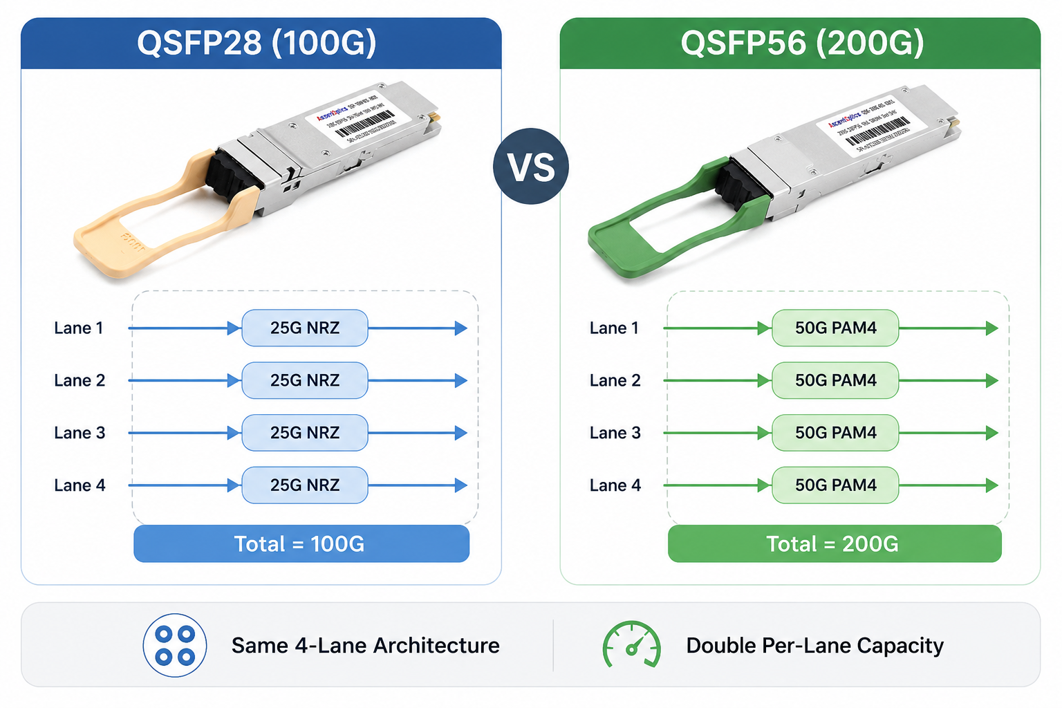
QSFP28 (Quad Small Form-factor Pluggable 28) is the dominant optical transceiver form factor for 100 Gigabit Ethernet. It uses four electrical lanes, each running at 25 Gbps, to deliver a total data rate of 100 Gbps. The signaling scheme is NRZ (Non-Return-to-Zero), a binary modulation format that transmits one bit per symbol.
Technical Foundation
A QSFP28 module combines four 25 Gbps lanes into one optical interface. Common configurations include:
- •100GBASE-SR4: four parallel 25 Gbps lanes over multimode fiber (MMF), typically reaching 70 m on OM3 or 100 m on OM4
- •100GBASE-LR4: four wavelengths multiplexed onto a single pair of single-mode fibers, reaching 10 km
- •100GBASE-CWDM4: four wavelengths on duplex single-mode fiber, reaching 2 km
- •100GBASE-PSM4: four parallel lanes on single-mode fiber, reaching 500 m to 2 km
- •100GBASE-ER4: up to 40 km
- •100G ZR4: typically 80 km or longer depending on implementation
QSFP28 modules comply with IEEE 802.3bm and the QSFP28 MSA. They are widely supported across Cisco, Arista, Juniper, NVIDIA/Mellanox, Huawei, and other switch platforms, making them the de facto standard for 100G data center links.
Common Use Cases
- •Leaf-to-spine links in 100G fabrics
- •Data center interconnects up to 10 km
- •Enterprise core and aggregation layers
- •4x25G breakout to server-facing 25G ports
Because the ecosystem is mature, QSFP28 modules are generally lower cost and lower risk than newer 200G options. For networks where 100 Gbps per port is sufficient, they remain a practical choice.
What Is QSFP56? The 200G Standard
QSFP56 (Quad Small Form-factor Pluggable 56) doubles the bandwidth of QSFP28 without changing the physical size. It supports 200 Gigabit Ethernet using four lanes at approximately 50 Gbps each. The key enabler is PAM4 (Pulse Amplitude Modulation 4-level) signaling, which encodes two bits per symbol instead of one.
Technical Foundation
A QSFP56 module uses four electrical lanes at 50 Gbps, with a line rate of 53.125 Gbps including encoding overhead. The aggregate data rate is 200 Gbps. Common optical variants include:
- •200GBASE-SR4: four 50 Gbps PAM4 lanes over MMF, reaching 70 m on OM3 or 100 m on OM4
- •200GBASE-FR4: four CWDM wavelengths over duplex single-mode fiber, reaching 2 km
- •200GBASE-LR4: four wavelengths over single-mode fiber, reaching 10 km
- •200GBASE-DR4: four parallel lanes over single-mode fiber, reaching 500 m
QSFP56 modules are based on the QSFP56 MSA and support 200GbE interfaces defined across IEEE 802.3bs, IEEE 802.3cd, IEEE 802.3cn, and IEEE 802.3cu standards. The 200GAUI-4 electrical interface carries four 53.125 Gbps PAM4 lanes between the host ASIC and the module. IEEE 802.3cd introduced 50G PAM4 lane technology and standardized 200GBASE-SR4 operation using four 50G lanes.
Common Use Cases
- •200G spine-layer upgrades in data centers
- •AI/ML cluster leaf-to-spine interconnects
- •5G transport midhaul aggregation
- •400G migration stepping stones using QSFP-DD platforms
AI training clusters are one of the fastest-growing QSFP56 deployment scenarios. Compared with 100G QSFP28 links, 200G QSFP56 connections can significantly reduce network oversubscription and improve GPU-to-GPU communication efficiency in distributed AI training environments.
For organizations that have outgrown 100G but are not ready for a full 400G deployment, 200G QSFP56 optical transceivers offer a balanced upgrade path.
QSFP28 vs QSFP56: Head-to-Head Comparison
The table below summarizes the core differences between QSFP28 and QSFP56 transceivers.
| Feature |
QSFP28 |
QSFP56 |
| Data rate |
100 Gbps |
200 Gbps |
| Electrical lanes |
4 x 25 Gbps |
4 x ~50 Gbps |
| Modulation |
NRZ (1 bit/symbol) |
PAM4 (2 bits/symbol) |
| Electrical interface |
100GAUI-4 |
200GAUI-4 |
| Form factor |
QSFP |
QSFP (same size) |
| Typical power |
3.5 W to 5.5 W |
4.5 W to 7.5 W |
| Common reach |
SR4 100 m, LR4 10 km |
SR4 100 m, FR4 2 km, LR4 10 km |
| Backward compatibility |
Works in QSFP56-capable ports with host support |
Does not work in QSFP28-only ports |
| Primary standards |
IEEE 802.3bm, QSFP28 MSA |
IEEE 802.3bs, IEEE 802.3cd, QSFP56 MSA |
| Typical use case |
100G leaf-spine, mature fabrics |
200G spine, AI/ML clusters, 400G migration |
Data Rate and Lane Architecture
QSFP28 delivers 100 Gbps across four 25 Gbps NRZ lanes. QSFP56 doubles that to 200 Gbps by running four ~50 Gbps PAM4 lanes in the same four-lane structure. The physical connector and cage are unchanged, but the electrical signaling is not interchangeable.
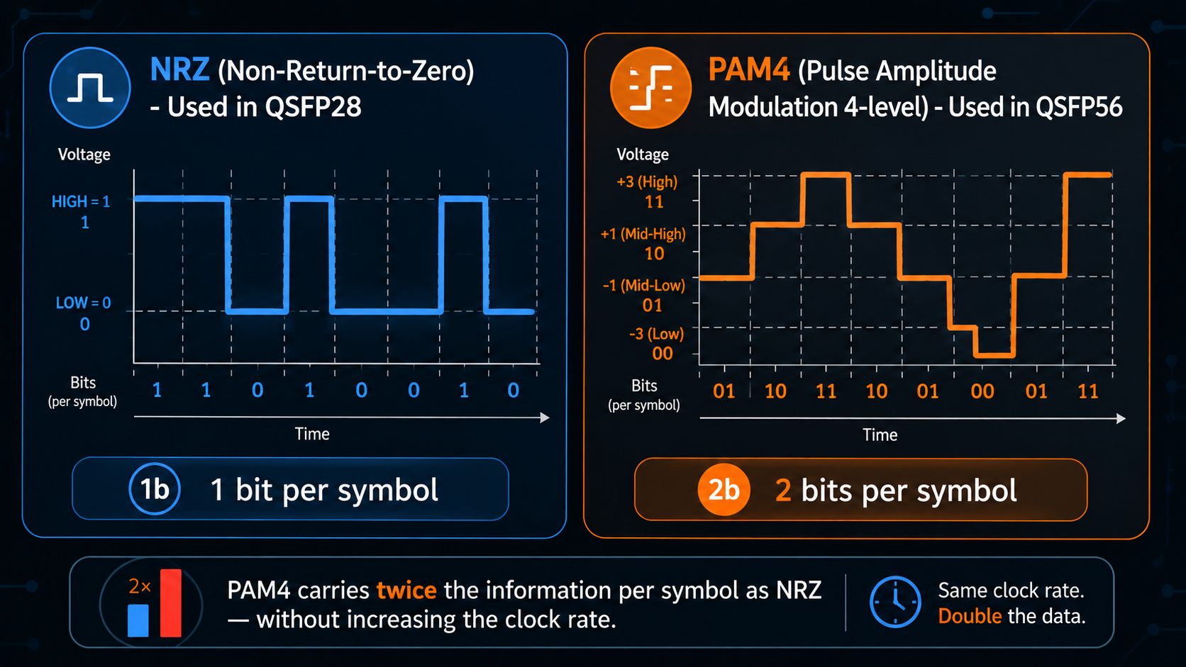
Modulation: NRZ vs PAM4
NRZ uses two voltage levels to represent 0 and 1. PAM4 uses four voltage levels to represent 00, 01, 10, and 11, effectively transmitting two bits per symbol. This doubling comes at the cost of reduced signal-to-noise margin and stricter forward error correction (FEC) requirements. We explore this in more detail in the next section.
Power Consumption and Thermal Design
QSFP56 modules consume more power than QSFP28 modules because of the higher-speed DSP and FEC logic required for PAM4. A typical QSFP28 module draws 3.5 W to 5.5 W, while a QSFP56 module draws 4.5 W to 7.5 W. In a fully populated 32-port switch, that difference can add 32 W to 64 W per switch. For hyperscale deployments with thousands of ports, thermal and power budgets matter.
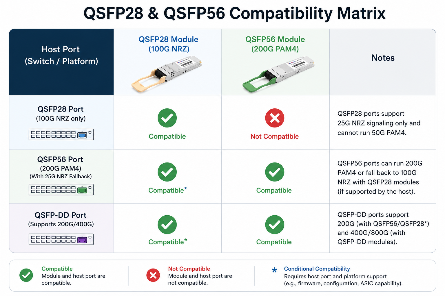
Backward and Forward Compatibility
The same QSFP cage accepts both modules, but electrical compatibility is directional:
- •A QSFP28 module can often operate in a QSFP56-capable port if the host supports 25G NRZ fallback.
- •A QSFP56 module cannot operate in a QSFP28-only port because the host lacks 50G PAM4 SerDes.
- •QSFP56 modules can plug into QSFP-DD ports that support 200G electrical modes, providing a forward path.
Always verify the switch datasheet, ASIC generation, firmware version, and port configuration before assuming interoperability.
Cost and Cost-per-Gbps
The sticker price of a QSFP56 module is higher than a comparable QSFP28 module, but the cost-per-Gbps is often lower. For example, replacing a $250 100GBASE-SR4 QSFP28 module with a $300 200GBASE-SR4 QSFP56 module nearly doubles bandwidth while increasing module cost by only about 20%. That translates to roughly 40% lower cost-per-Gbps, assuming the switch platform can use the extra capacity.
However, the total cost of ownership also includes switch ASIC upgrades, higher power draw, cooling, and potentially new cables. The economics favor QSFP56 when you need the bandwidth and can absorb the incremental power.
NRZ vs PAM4: Why Modulation Defines the Difference
The most important technical distinction between QSFP28 and QSFP56 is not the form factor. It is the modulation.
NRZ Encoding in QSFP28
NRZ is a binary modulation scheme. Each symbol carries one bit. The signal transitions between two voltage levels, representing 0 and 1. NRZ is simple, has good noise immunity, and has been the workhorse of 10G, 25G, and 100G Ethernet.
PAM4 Encoding in QSFP56
PAM4 uses four voltage levels to encode two bits per symbol. At the same baud rate, PAM4 carries twice as much data as NRZ. This is how QSFP56 achieves 50 Gbps per lane without doubling the clock rate. The trade-off is a smaller voltage eye between levels, which makes the signal more susceptible to noise and crosstalk.
FEC, DSP, and Signal Integrity
Because PAM4 has a lower noise margin, reliable operation requires stronger FEC and digital signal processing (DSP) in both the switch ASIC and the optical module. IEEE 802.3bs specifies Reed-Solomon FEC (RS-FEC) for 200GBASE optical links. This adds a small amount of latency but enables error-free transmission over standard fiber.
Cable quality, connector cleanliness, and PCB trace design also become more critical with PAM4. A marginal link that would work fine with NRZ may fail with PAM4 unless all components in the channel meet specifications.
Practical Impact on Network Design
When you move from QSFP28 to QSFP56, you are not just buying faster optics. You are committing to:
- •PAM4-capable switch ASICs
- •Stronger FEC configuration
- •Tighter signal-integrity requirements
- •Higher power and thermal budgets
This is why many engineers treat QSFP56 as a platform decision, not just a module upgrade.
Compatibility and Interoperability
Compatibility is the area where most mistakes happen. The modules share the same mechanical envelope, but the electrical interface is what determines whether a link comes up.
Can QSFP28 Work in a QSFP56 Port?
Often, yes. Many QSFP56-capable switch ports support speed fallback to 25G NRZ per lane, allowing a QSFP28 module to run at 100 Gbps. This depends on the switch ASIC, firmware, and vendor configuration. For example, some Arista 7060X4 and NVIDIA Spectrum-2/3 platforms support this mode. Check the vendor compatibility matrix before relying on it.
Can QSFP56 Work in a QSFP28 Port?
No. A QSFP28-only port uses 25G NRZ SerDes and cannot interpret the 50G PAM4 signaling from a QSFP56 module. The module may physically fit, but the link will not initialize.
Major Switch Platform Support
The following platforms are examples of hardware that support QSFP56; always confirm the specific SKU and software release:
- •Cisco: selected Nexus 9000 series switches with QSFP56-capable line cards
- •Arista: 7060X4, 7060X6, and 7170 series
- •Juniper: QFX5200, QFX5220, and PTX platforms
- •NVIDIA/Mellanox: Spectrum-2 (SN3700) and Spectrum-3 (SN4600) switches
- •Huawei: CloudEngine 9800, 8800, and 6800 series with 200GE interfaces
DAC and AOC Cable Compatibility
QSFP28 DACs and AOCs are generally not suitable for 200G QSFP56 links because the cable wiring and signal conditioning are designed for 25G NRZ per lane, not 50G PAM4. Some switches can down-rate a QSFP56 port to 100G and use a QSFP28 cable, but this is a host-dependent feature.
For native 200G links, use QSFP56-rated DACs or AOCs. For longer reaches, use the appropriate optical transceiver module matched to your fiber type and distance.
When to Choose QSFP28 vs QSFP56
The right transceiver depends on bandwidth needs, existing hardware, budget, and migration plans.
Choose QSFP28 If
- •Your network requires 100 Gbps per port today
- •You are extending an existing 100G fabric with mature, low-cost optics
- •Power and cooling budgets are constrained
- •Your switches are QSFP28-only and cannot be upgraded
- •You need maximum compatibility across vendor platforms
Choose QSFP56 If
- •Your spine layer needs 200 Gbps per port
- •You are building AI/ML or high-performance computing fabrics
- •Your switches support QSFP56 with 50G PAM4 SerDes
- •You want a lower cost-per-Gbps for high-bandwidth links
- •You plan to migrate to 400G QSFP-DD in the same chassis later
Skip Both and Go Directly to QSFP-DD or OSFP?
Sometimes yes. If you are deploying a new fabric and expect to need 400G within 12 to 24 months, choosing a QSFP-DD or OSFP switch platform from the start may be more cost-effective than an intermediate 200G step. These newer form factors support 400G and 800G using eight lanes, and many QSFP-DD ports can accept QSFP56 modules for 200G operation.
Migration and Future-Proofing
Moving from 100G to 200G is rarely a forklift upgrade. Most organizations phase it in based on traffic growth and hardware refresh cycles.
QSFP28 to QSFP56 Upgrade Path
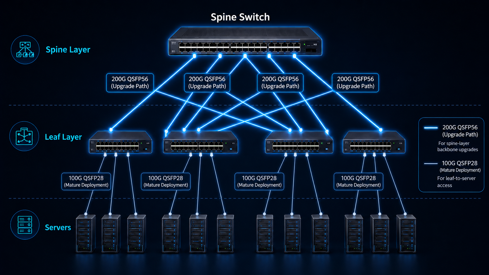
A common approach is to deploy QSFP56-capable switches only in the spine layer while keeping 100G leaf switches. This doubles spine capacity without touching the leaf layer. As leaf switches are refreshed, they can also move to 200G or remain at 100G with breakout cables.
QSFP56 as a Bridge to 400G
QSFP56 is often described as a bridge technology. It delivers 200G today and can be reused in QSFP-DD ports that support 200G electrical modes. When those ports are later upgraded to 400G, the QSFP56 modules can be redeployed elsewhere or phased out.
Rack-Level Density and Power Planning
A 32-port QSFP56 switch can deliver 6.4 Tbps of switching capacity in 1 RU. That density is attractive, but it also concentrates heat. Plan for:
- •Power consumption per module (5 W to 8 W typical)
- •Total switch power and thermal design power (TDP)
- •Front-to-back or back-to-front airflow alignment
- •Cable management for higher-density patching
Conclusion
QSFP28 and QSFP56 may look nearly identical from the outside, but they represent two different generations of Ethernet technology. QSFP28 remains the most widely deployed 100G solution thanks to its mature ecosystem, low power consumption, and cost-effectiveness. QSFP56, on the other hand, leverages PAM4 signaling to double bandwidth within the same form factor, making it an attractive option for AI infrastructure, cloud data centers, and next-generation network upgrades.
When choosing between QSFP28 and QSFP56, the decision should be based not only on current bandwidth requirements but also on switch compatibility, power budgets, and long-term migration plans. For organizations preparing for future 400G and 800G deployments, QSFP56 can serve as an efficient stepping stone toward higher-speed networking.
Frequently Asked Questions
Q1. What is the difference between QSFP56 and QSFP28?
QSFP56 supports 200 Gbps using four ~50 Gbps PAM4 lanes, while QSFP28 supports 100 Gbps using four 25 Gbps NRZ lanes. They share the same QSFP form factor but use different electrical signaling.
Q2. Is QSFP56 backward compatible with QSFP28?
Mechanically, both modules fit the same QSFP cage. Electrically, a QSFP56 port may accept a QSFP28 module if the host supports 25G NRZ fallback. A QSFP56 module will not work in a QSFP28-only port.
Q3. What is QSFP56 used for?
QSFP56 is used for 200 Gigabit Ethernet links in data center spine layers, AI/ML clusters, 5G transport networks, and as a stepping stone to 400G infrastructure.
Q4. How fast is QSFP56?
QSFP56 delivers 200 Gbps aggregate bandwidth. The “56” refers to the electrical lane capability of approximately 56 Gbps signaling, including encoding overhead.
Q5. Is QSFP56 the same as QSFP-DD?
No. QSFP56 keeps the standard QSFP form factor and supports up to 200G. QSFP-DD is a deeper module with an additional row of contacts and supports up to 400G or 800G.
Q6. What cables work with QSFP28 and QSFP56?
QSFP28 uses 100G-rated DACs, AOCs, or optical modules. QSFP56 requires 200G-rated DACs, AOCs, or optical modules. Do not assume a QSFP28 cable will work at 200G in a QSFP56 port.
Post Views: 46