On a Tuesday morning at 9:47 AM, James Okonkwo, a network engineer, was monitoring trading systems when several critical links suddenly dropped. The primary connections feeding the main trading room failed multiple times within minutes, disrupting transactions and effectively erasing approximately $150,000 worth of trading activity.
After replacing the module twice and rebooting the system, he eventually identified the root cause: a 2.1 dB loss on a single-mode LC connector caused by a barely visible fingerprint. Once cleaned, the link was fully restored, and everything returned to normal.
If you have encountered a similar situation, you are not alone. QSFP28s are generally reliable, but when they fail, you are left with vague symptoms that give immense pressure. This guide on QSFP28 troubleshooting gives you a step by step grounding in identifying trouble from the pressure-filled physical layering and switch configuration all the way to DDM diagnostics.
You will be learning to diagnose the QSFP28 not detected status, how to get away with link down and flapping, understand the DDM alarms, and interpret compatibility issues before they lead to outages. The approach works out on Cisco, Arista, and Juniper platforms.
If you need help with a specific failure that does not match the patterns here, contact our optical networking experts for direct engineering support.
Before You Begin: The QSFP28 Troubleshooting Toolkit
Good troubleshooting starts with the right tools. Keep these items accessible in your data center or network operations center:
- •Fiber inspection microscope or probe— to check connector end-face quality
- •Optical power meter— to measure actual Tx and Rx power levels
- •Light source or loopback module— to isolate cable vs module failures
- •Lint-free wipes and IPA cleaning fluid— for connector cleaning
- •Switch CLI access— to read DDM values, error counters, and port status
Most QSFP28 troubleshooting cases are resolved with one or two of these tools. The key is working through diagnostics in the correct order so that you do not chase symptoms instead of root causes.
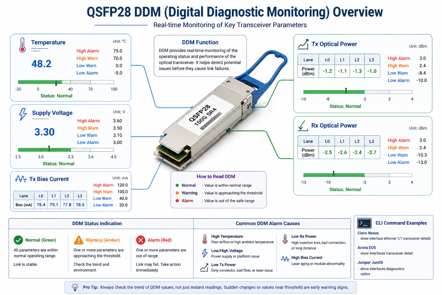
Understanding DDM and Alarm Thresholds
The DDM function is your best help in addressing any unwanted behavior in a QSFP28 module. It provides real-time values such as temperature, supply voltage, Tx bias current, Tx optical power, and Rx optical power, and triggers alarms when parameters exceed defined thresholds.
Understanding DDM thresholds helps determine whether the issue is related to the module itself, dirty connectors, fiber link problems, or switch thermal conditions. The following sections introduce specific alarm scenarios.
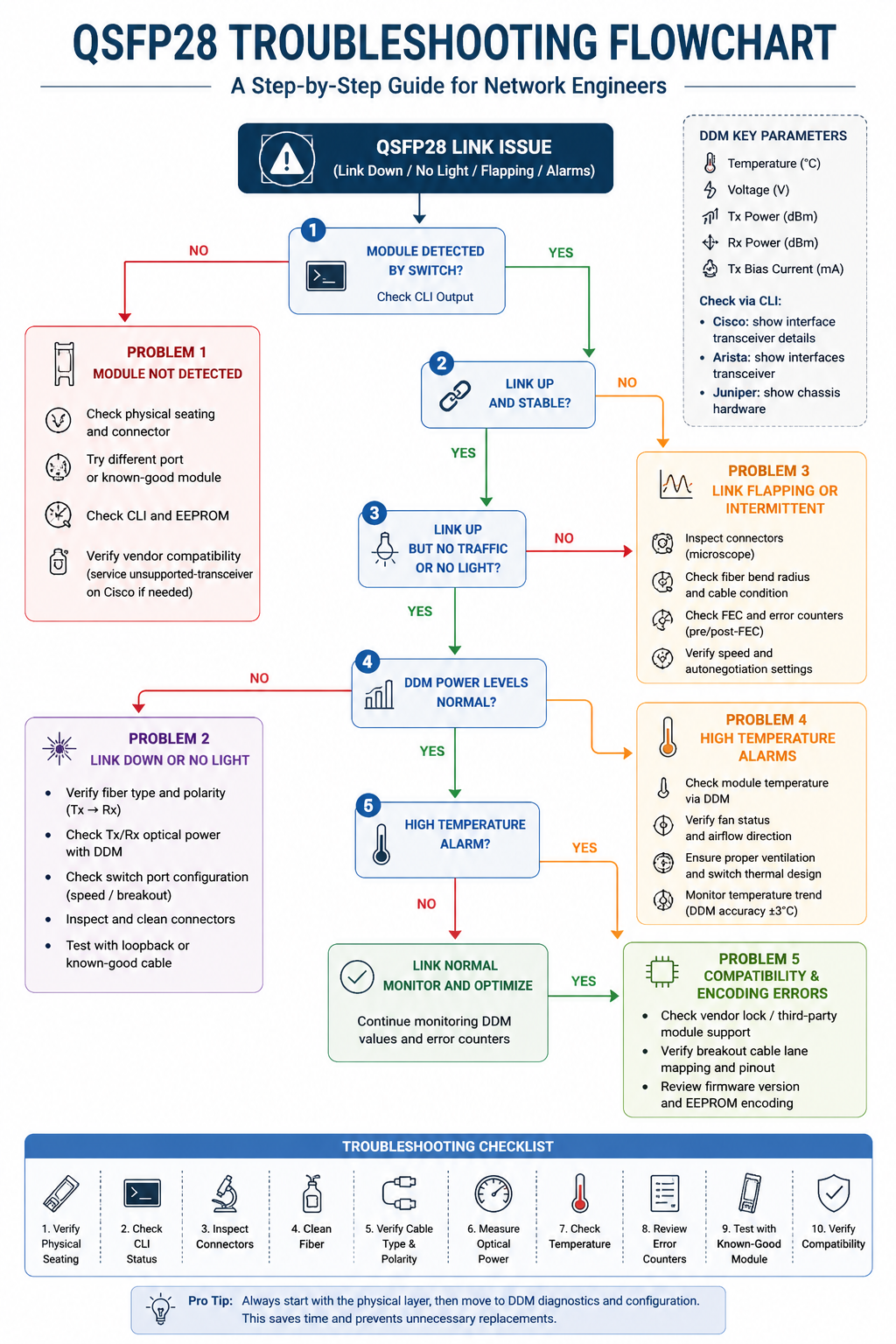
Problem 1: QSFP28 Module Not Detected
Physical Seating and Connector Checks
If the switch says that the transceiver is not present, you must start with the physical layer. Power is not required for QSFP28 modules for power down, but partially seating will prevent electrical connectivity.
Remove the module and inspect for debris, bent pins, or damage in the connector or cage. Reinsert it firmly until you hear a click. If the issue persists, try a different port or a known-good module. This simple swap helps isolate whether the issue is with the module, port, or switch.
Switch CLI Verification (Cisco, Arista, Juniper)
Each platform has a standard command to list inserted transceivers.
Cisco Nexus:
show interface ethernet 1/1 transceiver
Arista EOS:
show interfaces transceiver
Juniper JunOS:
show chassis hardware
If the CLI shows “Not present” or “Empty” after reseating, the switch is not reading the module EEPROM. Move to the next step.
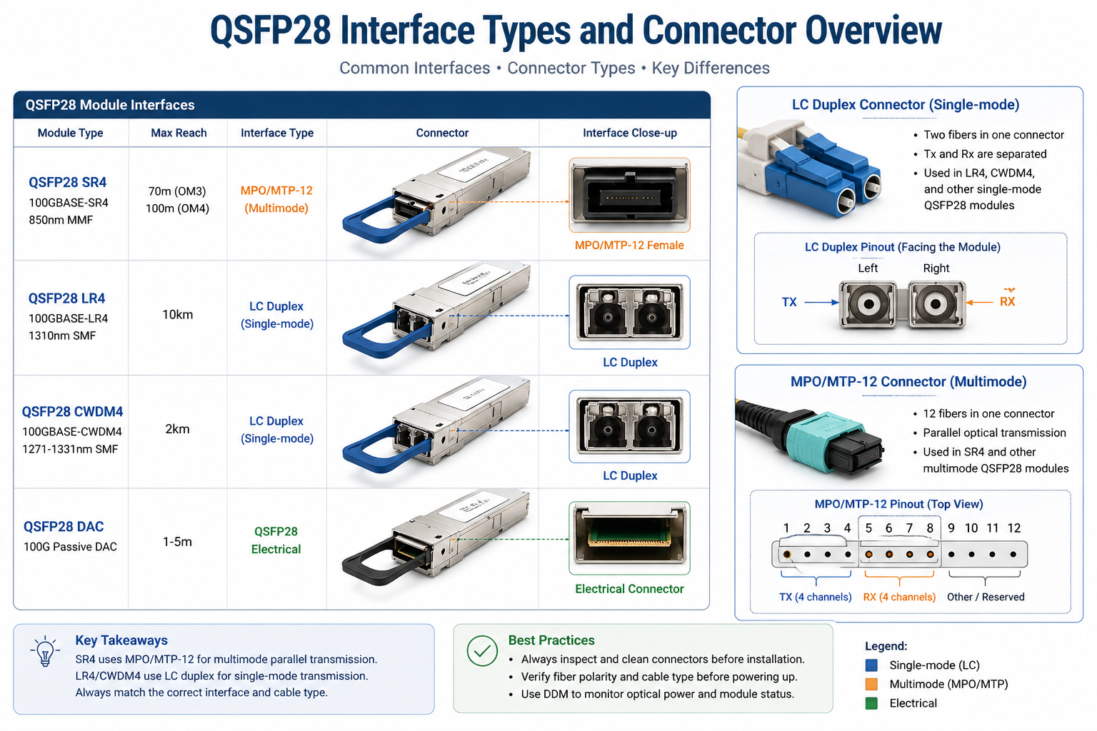
EEPROM and Vendor Compatibility Issues
QSFP28 modules store identification data in an EEPROM chip. The switch reads this data upon insertion to verify compatibility. If the EEPROM is unreadable, or if the switch vendor enforces a whitelist, the module may be physically present but logically undetected.
On some Cisco platforms, third-party modules require the hidden command:
service unsupported-transceiver
On Arista, most third-party modules are accepted, though certain firmware versions may flag unknown vendors. On Juniper, refer to the official compatibility matrix.
If you are deploying third-party modules and encounter detection issues across multiple switches, contact our engineers to verify EEPROM encoding and compatibility.
Problem 3: QSFP28 Link Flapping or Intermittent Connectivity
Identifying Cable and Connector Problems
Two most mortifying moments when QSFP28 troubleshooting can seem to be totally justified by link flapping. The link goes up, passes traffic and then goes down without warning. Mostly, the root cause is marginal connection – it may physically look good but fail under vibration, temperature, or traffic load.
Have a look at the fiber connectors under a microscope. Look to see scratches, pits, chips, or contamination. It is amazing how many times something so small can cause enough reflection or loss to upset a 25G NRZ lane.
Be very observant of the bend radius. One single tight bend with 30 mm radius (on single mode fiber) can give an additional 0.5 dB or more in loss. That may be enough to bring the flapping on a long-reach link from stable.
FEC and Signal Integrity Issues
We find that in some DAC cables or worse than marginal fiber technology cases, the link needs the forward error correction (FEC) to obtain stability. In case the bit error rate goes near the FEC threshold, the link comes up and down as the receiver reaches for a threshold lock.
Check switch error counters for pre-FEC or post-FEC errors; a rising number of pre-FEC errors is generally indicative of a physic ally layer problem, while post-FEC error rise indicates link is working on the edge of operability and is in need of cable or module replacement.
Autonegotiation and Speed Mismatches
Typically, QSFP28 connections do not autonegotiate speeds. One end must be manually setup for 100G, and the other end should also be manually configured to 100G. If the ends are set to 100G and 40G or 100G and auto, please note that in this case, the link might flap continuously or stay down. Verify configuration on both ends of the links before blaming the QT.
Problem 4: QSFP28 High Temperature Alarms
Normal Operating Ranges by Module Type
DDM temperature alarms are common in high-density switches. Before reacting, know what normal looks like. Commercial-grade QSFP28 modules are typically rated for 0°C to 70°C case temperature.
A reading of 65°C on an ER4 module in a summer data center may be warm but within spec. A reading of 65°C on an SR4 module in a climate-controlled room is a warning sign.
Airflow and Switch Thermal Design
High temperatures are often a switch-level problem, not a module-level problem. Check the switch fan status and airflow direction. A failed fan, blocked vent, or reversed airflow can cause module temperatures to rise across an entire switch.
If you are running fully loaded 64-port switches, verify that your thermal design accounts for the aggregate heat load. Our QSFP28 power consumption guide includes detailed thermal planning calculations.
When a High Temperature Reading Is False
The accuracy of the DDM temperature readings is specified at approximately ±3°C. Estimations can be made on thermal spontaneousity when a single module reads 5°C hotter than its neighbors. If the temperature is going up with time, it is definitely genuine. In the optical module thermal runaway could further lead to wavelength drift, amplified Bit Errors, and eventual link failure.
Problem 5: QSFP28 Compatibility and Encoding Errors
Vendor Lock and Third-Party Module Detection
Most of the big switch manufacturers have different attitudes toward third-party QSFP28 modules. There are manufacturers that will accept any modules compliant with the MSA standard. However, others might trigger warnings or only work with DDM polling totally deactivated.
Should you ever see “Not supported” or “Unknown” within the transceiver menu, this indicates vendor lock features within the switch components. Some firmware upgrade or perhaps some secret viable command could solve in those situations. In other instances, companies may dictate the use of modules encoded within the switch’s EEPROM.
A Data Center engineer in Dallas had installed some of these third-party QSFP28 modules in the fresh Cisco switches. The modules have good physical seating but came up with “Not supported” across all eight ports, both ways with show interface transceiver. In brief, after turning on service unsupported-transceiver with a reload of the line-card on the supervisor, all eight links came up instantly.
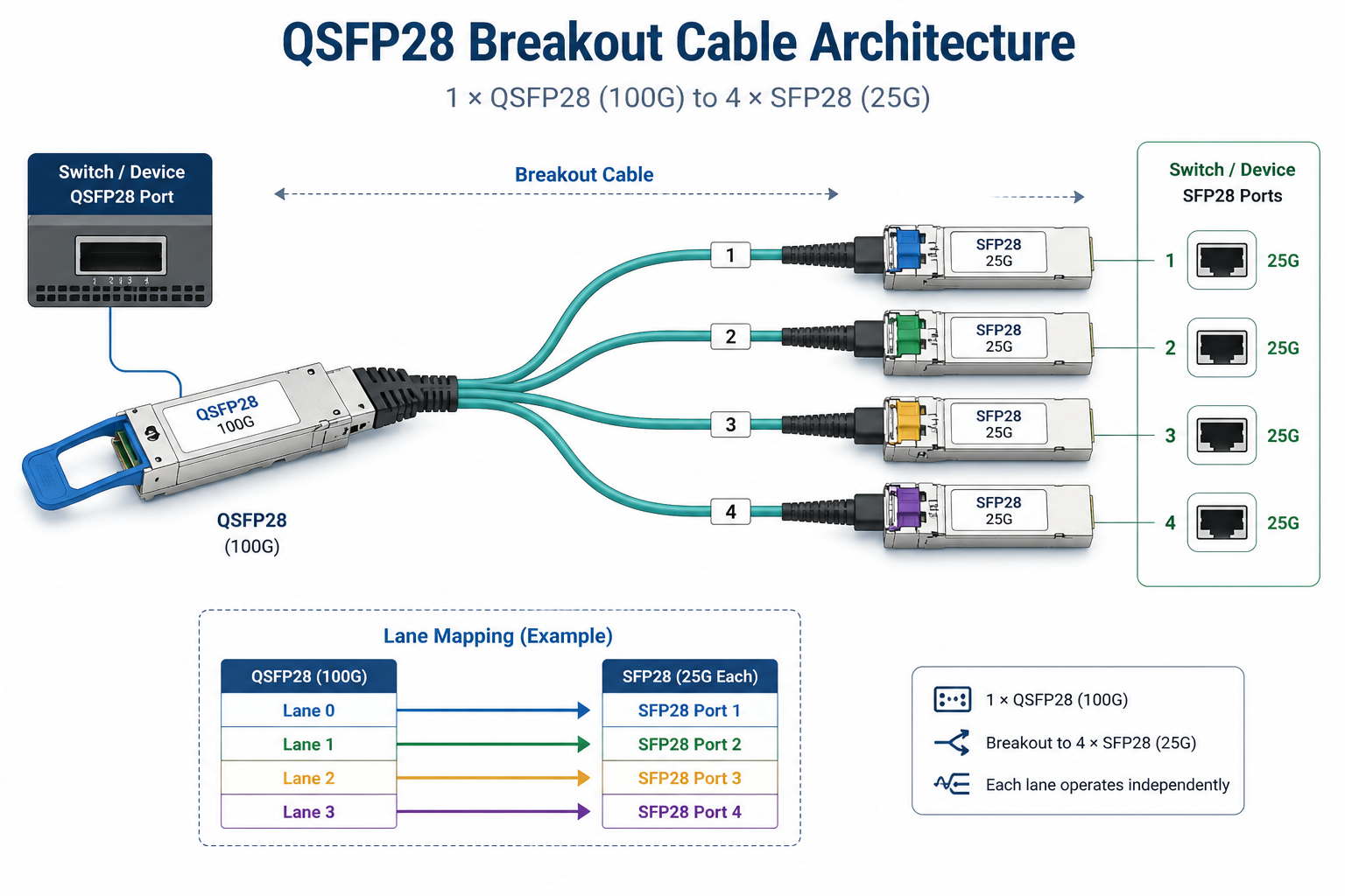
Breakout Cable Lane Mismatches
Partial-link failures are generally a common problem with breakout cables. One-to-four SFP28 passive breakout cables usually should suit both the electrical lane mapping of the switch and the optical lane mapping of the cable.
If three lanes (ports) come up-you cable out-of-the box on units T13 pins T14, T15, and T16 lanes, in figures through numbers supported by switches-on the QSFP28, but lane 2 remains down, then there is a problem in the lane-mapping mismatch happening between the cable and the switch breakout group. T13-16 pinout differences exist, so not all switches can support every variant. Please refer to the switch datasheet for the applicable breakout cable type.
If you are troubleshooting breakout issues, our QSFP28 breakout cable guide has detailed pinout and compatibility information.
Firmware and EEPROM Encoding Issues
FW update, on occasion, changed transceiver EEPROM parsing. What used to be fine on fwv 9.2 might be marked as being incompatible on fwv 9.3. Should you find out that the transceiver fails to be detected or that the link is down straight after the switch upgrade, consult the vendor’s release notes to find transceiver compatibility changes.
Reading QSFP28 DDM and Error Counters
DDM Alarm Threshold Reference Table
Use this table as a quick reference when interpreting DDM alarms on standard commercial-grade QSFP28 modules.
| Parameter |
High Alarm |
Low Alarm |
Typical Normal Range |
| Temperature |
+70°C to +75°C |
-5°C to 0°C |
35°C – 55°C |
| Voltage |
3.60 V |
3.00 V |
3.20 – 3.40 V |
| Tx Power (SR4) |
+3.0 dBm |
-10.0 dBm |
-8.4 to +2.4 dBm |
| Rx Power (SR4) |
+3.0 dBm |
-13.0 dBm |
-10.3 to +2.4 dBm |
| Tx Bias Current |
120% of rated |
10% of rated |
Varies by module |
Exact thresholds vary by manufacturer and module reach. Always check the module datasheet if the numbers look unexpected.
Interpreting BIP/BECN and CRC Errors
Beyond DDM, switch error counters reveal link quality trends.
- •BIP (Bit Interleaved Parity) errorsindicate physical layer bit errors before FEC correction.
- •CRC errorsindicate frame corruption detected at the MAC layer.
- •Symbol errorsindicate serdes-level signal integrity problems.
A low but steady count of BIP errors suggests a marginal optical connection. A sudden spike in CRC errors often correlates with link flapping or temperature excursions.
When to Replace vs. When to Reseat
Before replacing a QSFP28 module, run through this quick decision tree:
- 1. Reseat firstif the module is not detected or if DDM shows no light on one lane.
- 2. Clean connectors firstif the link is flapping or Rx power is low.
- 3. Swap with a known-good moduleif reseating and cleaning do not help.
- 4. Replace the cableif the known-good module shows the same symptoms.
- 5. Replace the moduleonly after you have ruled out the port, the cable, and the connectors.
Following this sequence saves money and prevents unnecessary RMAs.
QSFP28 Troubleshooting Checklist
Use this checklist in the field when a QSFP28 link fails.
- 1. Verify physical seating— Remove and firmly reinsert the module until the latch clicks.
- 2. Check switch CLI— Confirm the module is detected and the port is configured for 100G.
- 3. Inspect fiber connectors— Use a microscope to look for contamination, scratches, or chips.
- 4. Clean connectors— Wipe both ends with lint-free wipes and IPA if any contamination is visible.
- 5. Verify cable type and polarity— Match multimode vs single-mode and confirm MPO/LC polarity.
- 6. Measure optical power— Compare Tx and Rx DDM values against module specifications.
- 7. Check temperature— Verify the module is not operating above its rated case temperature.
- 8. Review error counters— Look for BIP, CRC, or symbol error trends.
- 9. Test with a known-good module— Isolate module vs port vs cable failures.
- 10. Verify vendor compatibility— Check for vendor lock, firmware restrictions, or unsupported transceiver messages.
Conclusion
Not all issues with QSFP28 modules should be handled by guesswork. Follow a structured approach, initiaiting with the physical layer, then DDM diagnostics, finally configuration, to narrow down and fix most of the problems without grasping at the reasons for module replacement.
Remember at least the dirty connectors, configuration mismatches, and compatibility restraints as the top three common culprits. In starting from there, you would be in a position to solve most QSFP28 troubleshooting situations within minutes instead of prolonging the agony.
If you need vendor-specific compatibility validation or help with a failure that does not fit the standard patterns, contact our optical networking experts. Ascent Optics engineers can walk you through diagnostics and verify module compatibility for your specific switch platforms.
For more guidance on choosing and deploying QSFP28 modules, read our QSFP28 transceiver guide. If you want to understand power and thermal planning in depth, see our QSFP28 power consumption guide. And for breakout-specific advice, visit our QSFP28 breakout cable guide.
To explore Ascent Optics’ full range of QSFP28 optical modules, view our QSFP28 transceiver solutions.
Frequently Asked Questions
Q1. Why does the QSFP28 link flap off and on?
Dirty or damaged fiber connectors, tight fiber bends causing excessive loss, nearly faulty signal integrity threshold control, and autonegotiation and speed mismatch at both linking ends are common causes for QSFP28 links to flap.
Q2. How can I check DDM values on a QSFP28 module?
The switch CLI is used. Cisco: show interfaces transceiver. Arista: show interfaces transceiver. Juniper: show chassis pic fpc-slot x pic-slot y. DDM gives the temperature, voltage, Tx power, Rx power, and bias current.
Q3. What is the typical temperature within a QSFP28 module?
Most QSFP28 models for industrial use operate load-junction temperatures between 35°C and 55°C, and their maximum rated case temperature can reach 70°C. For example, long-reach modules like ER4 and ZR4 will most-often heat up more than an SR4 module.
Q4. Can I install third-party QSFP28 modules into Cisco systems?
In many cases, yes, but for some Cisco platforms, a hidden command access is necessary for the ordering and setting of the service unsupported-transceiver; in other cases, third-party modules will not allow DDM polling or other features. Always make pre-deployment tests.
Post Views: 719