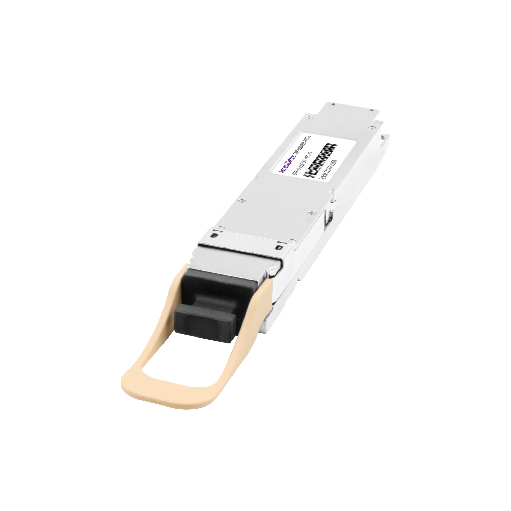
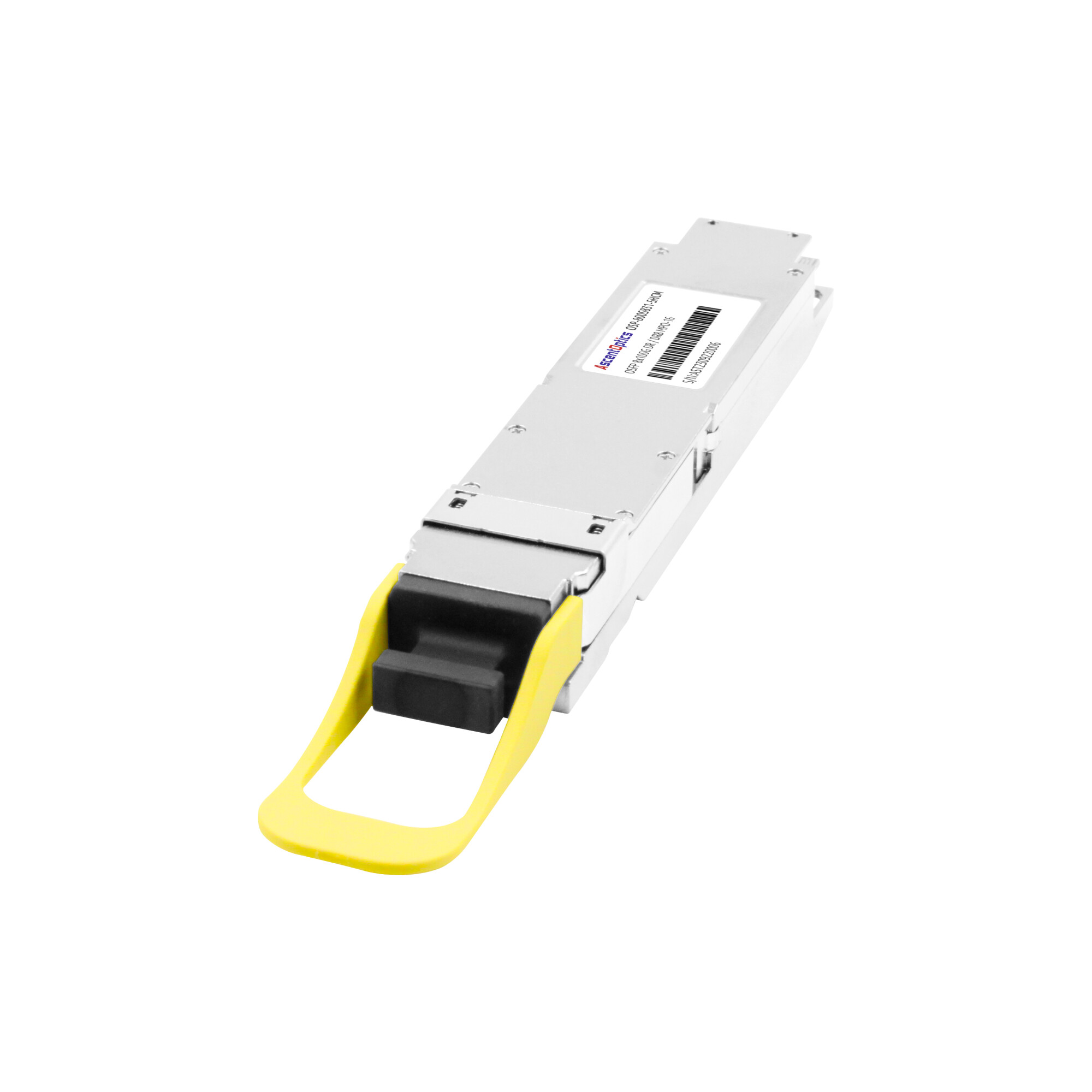
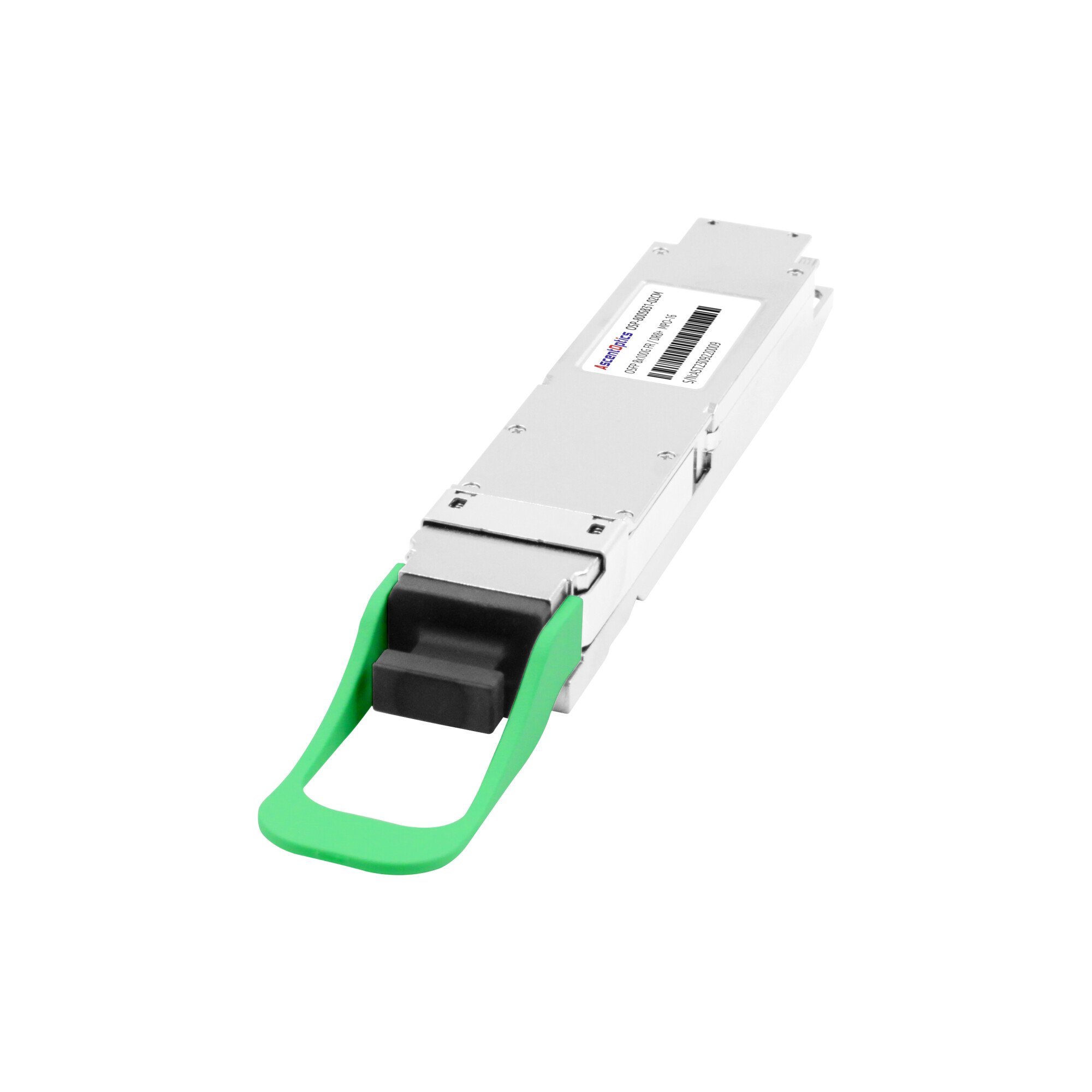
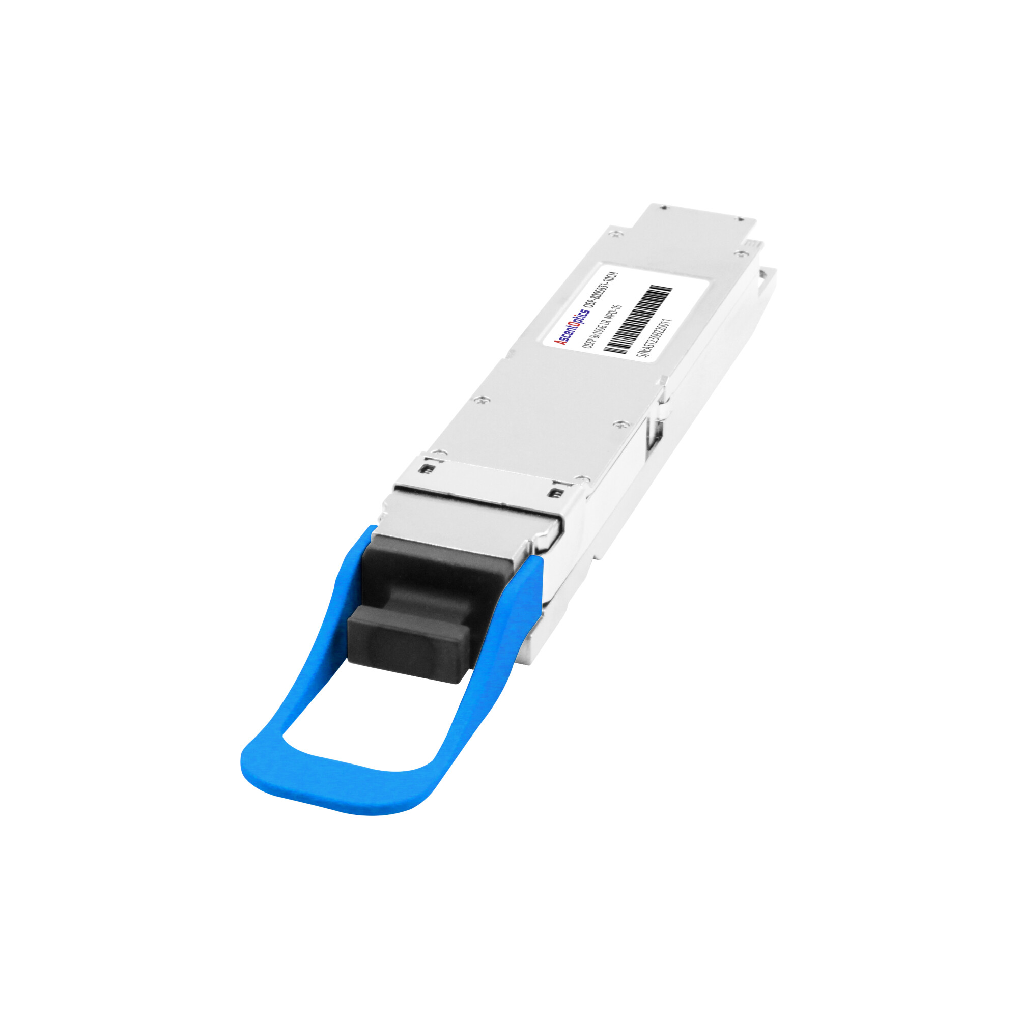
PAM4 has become a key signaling technology in modern high-speed optical transceivers, particularly in 400G and 800G applications. By encoding two bits per symbol, PAM4 doubles the data rate compared with NRZ at the same baud rate, enabling higher bandwidth without proportionally increasing the number of transmission lanes.
You already know PAM4 matters, even if you have never dissected it. You see it in every “400G DR4” and “800G SR8” spec you evaluate. What you may not have seen is a clear explanation of how the signal actually works, why it demands a DSP and forward error correction, and what that means when you choose a transceiver.
What Is PAM4?
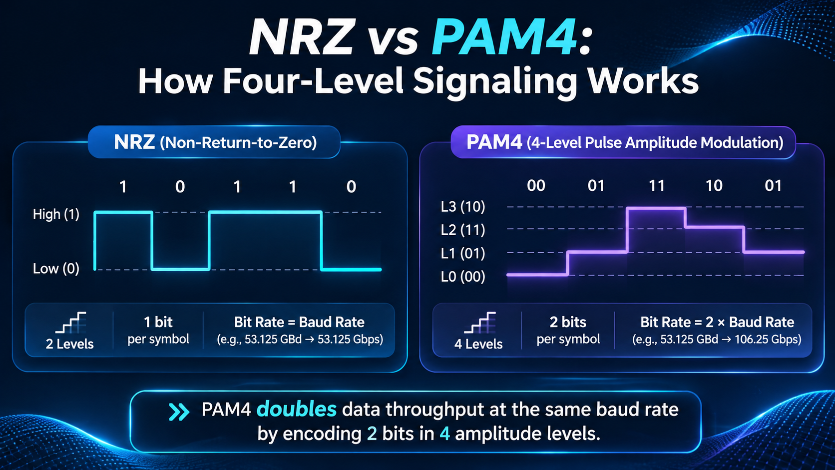
PAM4 is a signaling method that encodes data into four distinct amplitude levels, carrying two bits of information in every transmitted symbol instead of the single bit carried by traditional NRZ.
PAM4 stands for 4-level Pulse Amplitude Modulation. In a conventional NRZ (non-return-to-zero) signal, the transmitter chooses between two voltage levels: a low level for a binary 0 and a high level for a binary 1. One symbol, one bit. PAM4 adds two intermediate levels, giving the transmitter four options per symbol. Because four levels can represent four two-bit combinations (00, 01, 11, and 10), each PAM4 symbol carries twice as much information as an NRZ symbol at the same baud rate.
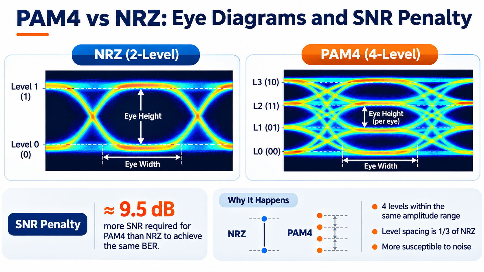
The cost of that doubling is signal margin. When you squeeze four levels into the same voltage range that NRZ uses for two, the levels sit one-third as far apart. Noise that NRZ would shrug off can push a PAM4 level across a decision threshold and corrupt a bit. That is why PAM4 is inseparable from the DSP equalization and forward error correction covered later in this guide.
For a concrete sense of scale, consider the transition the industry already made. A 100GBASE-LR4 module uses four 25G NRZ lanes. A 400G DR4 module uses four 100G PAM4 lanes. Same lane count, four times the throughput. PAM4 is the difference.
Related: To see how this maps to a specific speed generation, start with our What Is 800G?
How PAM4 Works: Symbol Mapping and Gray Coding
Four Levels, Two Bits: The PAM4 Symbol Alphabet
PAM4 defines four amplitude levels, conventionally labeled from lowest to highest. Each level maps to a two-bit value. The mapping is not arbitrary, and getting it wrong in a diagram is a fast way to lose an engineering audience.
The standard mapping assigns the levels in this order, from lowest voltage to highest:
- Level 0: 00
- Level 1: 01
- Level 2: 11
- Level 3: 10
Notice the pattern: the two-bit values follow Gray code order, not binary counting order. Binary counting would go 00, 01, 10, 11. Gray code deliberately swaps the last two so that adjacent levels always differ by exactly one bit.
Gray Coding and Why It Minimizes Bit Errors
Gray coding minimizes the number of bit errors caused by incorrect decisions between adjacent PAM4 levels. Since neighboring levels differ by only one bit, a typical adjacent-level symbol error results in a single-bit error rather than multiple bit errors. This helps reduce the overall bit error rate and improves the effectiveness of the transmission system when combined with FEC.
That single detail measurably improves the post-FEC bit error rate, because forward error correction fixes isolated single-bit errors far more efficiently than bursts. The 00, 01, 11, 10 pattern is not a stylistic choice. It is an error-resilience optimization built directly into the modulation format.
Baud Rate vs Bit Rate
PAM4 decouples two numbers that engineers often blur together. The baud rate is the number of symbols per second. The bit rate is the number of bits per second. With PAM4, the bit rate is always double the baud rate.
A typical 100G PAM4 lane operates at 53.125 GBd. Since each symbol carries two bits, the gross signaling rate is 106.25 Gbps. After accounting for FEC and other protocol overhead, the lane supports a nominal 100 Gbps data rate. This distinction explains why the baud rate and the effective data rate are not identical.
PAM4 vs NRZ: Key Differences
The cleanest way to understand PAM4 is to place it next to the NRZ signaling it replaced.
The SNR Penalty Explained
PAM4 has a smaller voltage separation between adjacent signal levels than NRZ when both use the same overall signal swing. This reduces the noise margin and makes PAM4 more sensitive to noise and distortion. A commonly cited theoretical SNR penalty is approximately 9.5 dB under specific comparison conditions, although the actual system-level penalty depends on the receiver design, signal quality, and FEC implementation.
That penalty is partially offset by the fact that PAM4 needs only half the baud rate for the same bit rate, which reduces bandwidth-related noise. But the net result is unchanged: PAM4 is a noisier, more fragile signal that only works because the industry paired it with DSP equalization and strong forward error correction.
Three Decision Thresholds Instead of One
NRZ has a single decision threshold. The receiver asks one question: is the sample above or below the midpoint? PAM4 asks three questions, one at each boundary between adjacent levels. Three thresholds means three times the opportunities for a noise spike to land on the wrong side. That is why a PAM4 eye diagram shows three stacked eyes rather than the single eye of NRZ.
When Each Modulation Format Makes Sense
| Attribute |
NRZ |
PAM4 |
| Bits per symbol |
1 |
2 |
| Amplitude levels |
2 |
4 |
| Baud rate for 100G per lane |
N/A (25G per lane typical) |
53.125 GBd |
| SNR requirement |
Lower |
~9.5 dB higher at same baud |
| DSP/FEC required |
Usually not |
Mandatory |
| Typical speeds |
10G, 25G, 100G (LR4) |
50G, 100G, 200G per lane |
NRZ remains the right tool at 10G and 25G per lane, where its simplicity and signal margin outweigh its lower spectral efficiency. PAM4 takes over at 50G per lane and above, where doubling bits per symbol is the only practical way to push more bandwidth through existing lanes without doubling the number of lasers and fibers.
Why PAM4 Needs DSP and FEC
PAM4 signals are more sensitive to noise, distortion, and inter-symbol interference than NRZ signals. In conventional DSP-based optical transceivers, digital signal processing plays an important role in compensating for channel impairments and improving signal quality. However, alternative architectures such as LPO reduce or eliminate the module-side DSP by relying more heavily on host-side signal processing.
Noise, Dispersion, and Inter-Symbol Interference
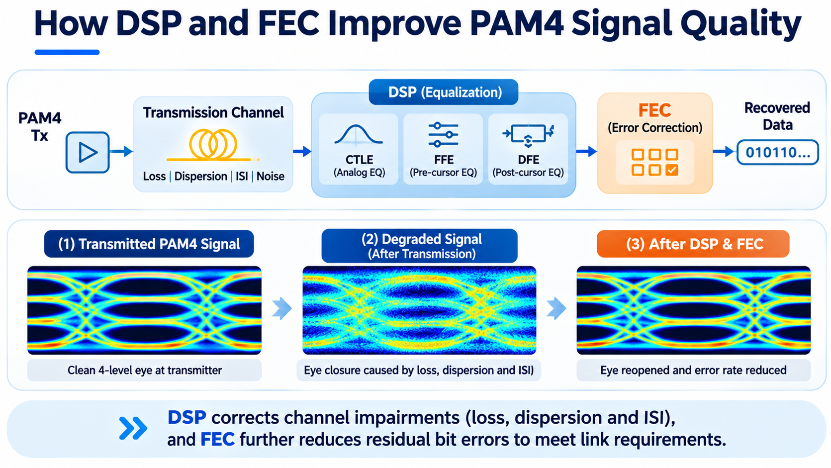
A PAM4 signal degrades as it travels through a PCB trace, a connector, or a length of fiber. High-frequency loss rounds off the sharp transitions between levels. Chromatic dispersion smears symbols in time so that one symbol bleeds into the next, a phenomenon called inter-symbol interference (ISI). Because PAM4 levels are already close together, even modest ISI can close the eye completely.
DSP Equalization: CTLE, FFE, and DFE
A digital signal processor inside the transceiver reverses much of that damage. The equalization chain typically includes three stages:
- CTLE (continuous-time linear equalizer): An analog equalizer that boosts high-frequency components to compensate for channel loss.
- FFE (feed-forward equalizer): A linear filter that processes the received signal to compensate for channel distortion and reduce inter-symbol interference.
- DFE (decision-feedback equalizer): A nonlinear equalizer that uses previously detected symbols to cancel post-cursor inter-symbol interference.
Together, these reopen the eye enough for the receiver to make reliable decisions. This DSP is the single largest consumer of power and cost in a modern 400G or 800G PAM4 transceiver, which is why the LPO movement described later tries to remove it.
Forward Error Correction and the BER Waterfall
Even a well-equalized PAM4 link has a raw error rate too high for any real network. Forward error correction (FEC) closes the gap. The transmitter adds redundant bits using forward error correction codes, such as KP4-FEC (RS(544,514)), and the receiver uses the redundant information to detect and correct transmission errors.
In many Ethernet optical interfaces, FEC encoding and decoding are performed by the host ASIC rather than inside the optical transceiver. The exact implementation depends on the interface architecture.
The acceptable pre-FEC BER depends on the FEC scheme and interface specification. For example, approximately 2.4E-4 is commonly referenced as a pre-FEC BER threshold for certain KP4-FEC applications. When the input error rate remains within the FEC correction capability, the decoder can significantly reduce the residual post-FEC BER. The actual post-FEC performance depends on the FEC implementation and operating conditions.
Reading a PAM4 Eye Diagram
The eye diagram is where PAM4 becomes tangible. If you have ever watched a vendor demo or opened a scope capture, this section gives you the vocabulary to interpret what you are seeing.
Three Eyes, Not One
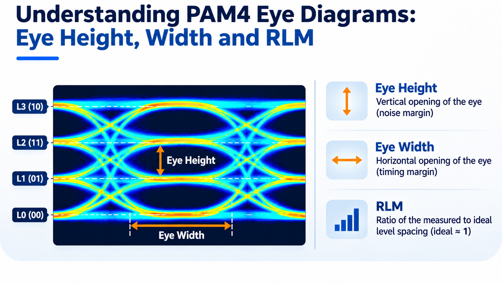
A PAM4 eye diagram shows three stacked eyes, one between each pair of adjacent levels: the lower eye, the middle eye, and the upper eye. A fully open PAM4 eye is actually three smaller eyes, each narrower and shorter than the single eye of an NRZ signal. A “good” PAM4 eye does not look clean in the way an NRZ eye does; it looks like three tight slivers.
Eye Height, Eye Width, and RLM
Three measurements matter most:
- Eye height describes the vertical opening and reflects how much noise the link can tolerate before a level is misread.
- Eye width describes the horizontal opening and reflects timing margin against jitter.
- RLM (Ratio of Level Mismatch) measures the uniformity of the four PAM4 signal levels. A lower RLM indicates greater deviation from ideal level spacing, which can increase signal distortion and reduce eye openings. The impact depends on the specific pattern of level mismatch.
TDECQ and Transmitter Quality
TDECQ (Transmitter and Dispersion Eye Closure for PAM4) is a standardized metric used to evaluate PAM4 optical transmitter performance. It estimates the additional optical power required by a reference receiver to achieve a specified BER compared with an ideal reference transmitter. A lower TDECQ value generally indicates better transmitter signal quality. When two transceivers pass the same spec sheet but behave differently in the field, TDECQ is often where the difference lives.
PAM4 in 400G Optical Transceivers
PAM4 became a commercial reality in the 400G generation, and that is where its architecture is easiest to understand.
The 4 x 100G Lane Architecture
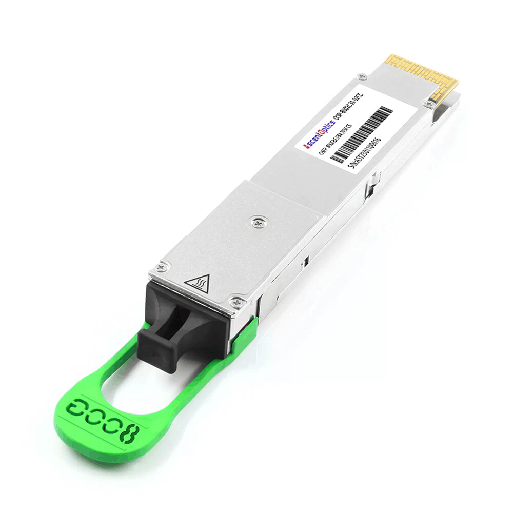
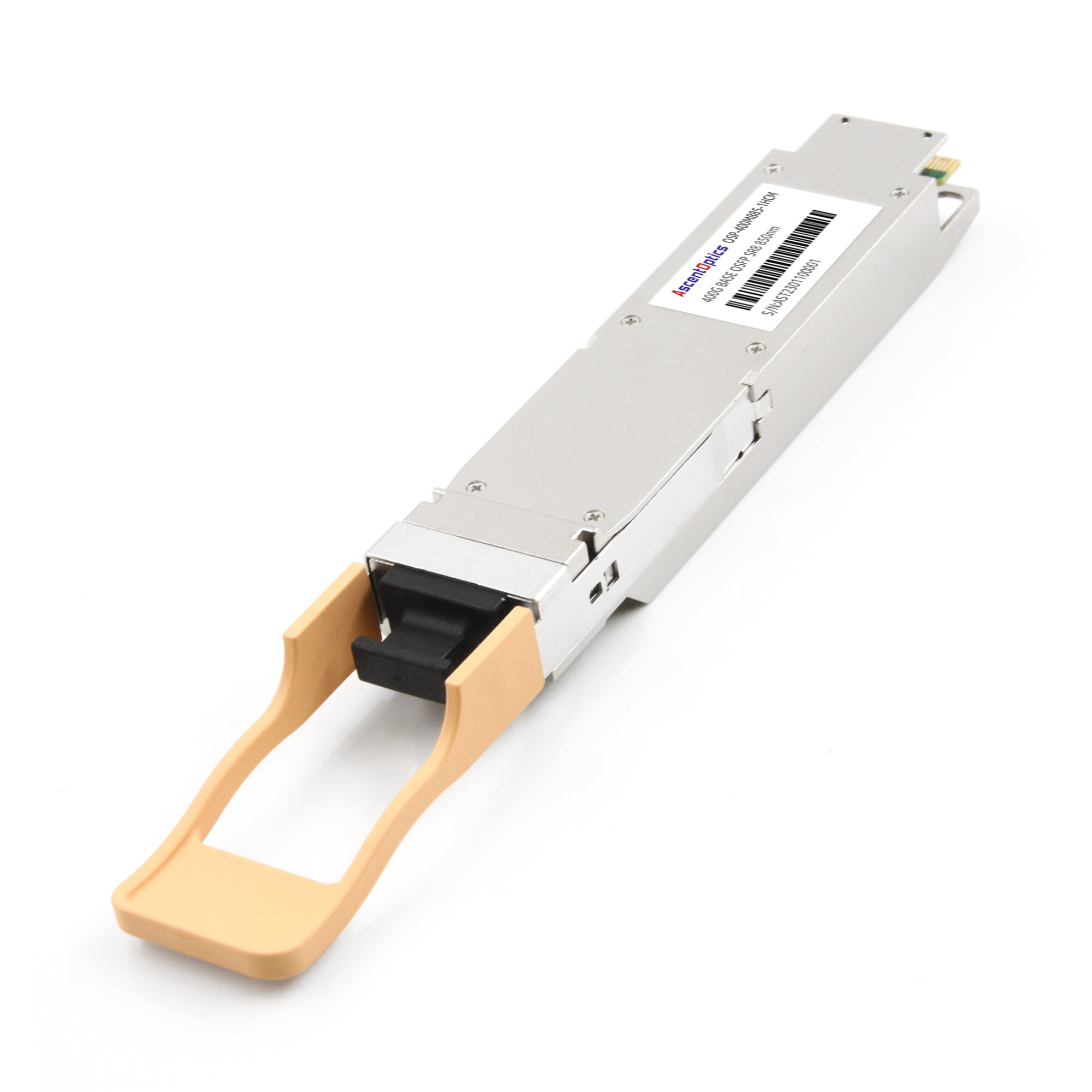
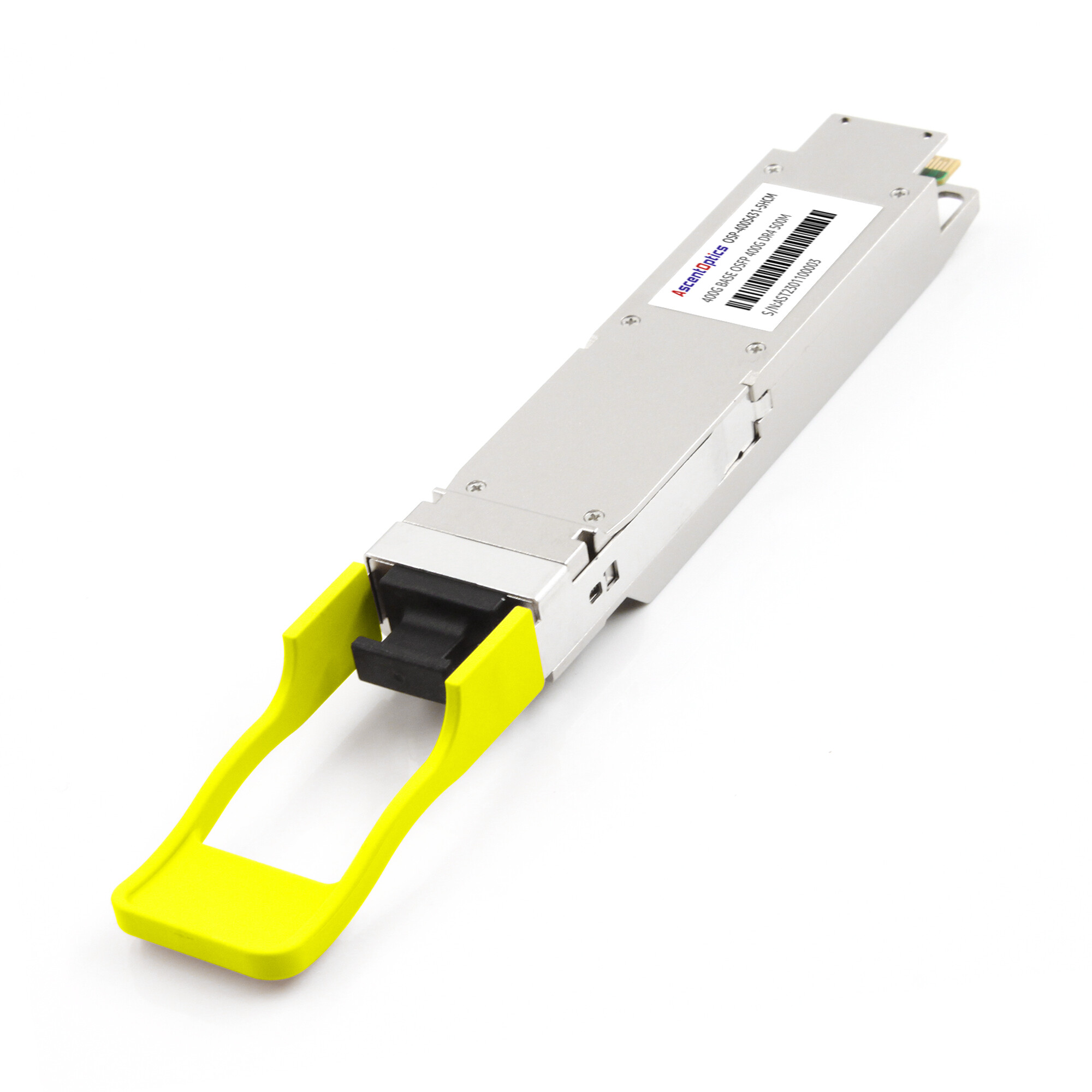
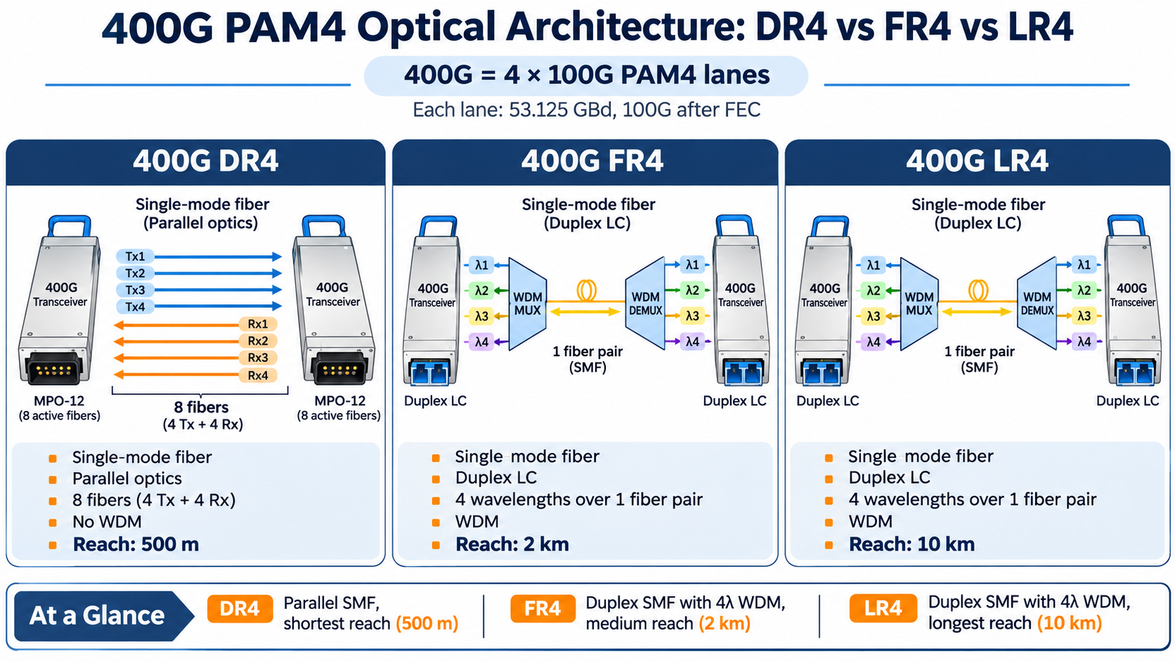
Many 400G optical transceivers use 100G PAM4 lanes, while others adopt different lane configurations depending on the optical standard. For example, 400G DR4 uses four 100G PAM4 optical lanes, whereas 400G SR8 uses eight 50G PAM4 lanes. These architectures demonstrate how PAM4 supports different combinations of lane count and per-lane data rate.
DR4, FR4, and LR4 Reach Differences
The 400G family splits into variants by reach and fiber type:
| Variant |
Fiber |
Reach |
Multiplexing |
| 400GBASE-DR4 |
Single-mode (4 fibers) |
~500 m |
None (parallel) |
| 400GBASE-FR4 |
Single-mode (1 pair) |
~2 km |
4 wavelengths |
| 400GBASE-LR4 |
Single-mode (1 pair) |
~10 km |
4 wavelengths |
PAM4 direct-detection optics are widely used in short- and medium-reach applications, including links up to 10 km. However, 10 km is not a fundamental physical limit of PAM4. The achievable reach depends on the optical budget, fiber characteristics, dispersion tolerance, receiver sensitivity, and signal processing capabilities. For longer-reach applications, coherent optical technology is often preferred because of its advanced signal processing and dispersion compensation capabilities.
Silicon Photonics and the DSP Gearbox
Inside many 400G modules, a silicon-photonics engine modulates the four lanes and a DSP performs the equalization and FEC. In some transceiver designs, a gearbox converts between different electrical and optical lane configurations. For example, a 400G module may map eight 50G electrical lanes to four 100G optical lanes, depending on its host interface and internal architecture. Understanding that internal mapping matters when you debug a module that links at the electrical level but fails at the optical level.
For the form-factor side of this story, see our 400G QSFP-DD transceiver guide.
PAM4 in 800G and 1.6T Optical Transceivers
8 x 100G PAM4 for 800G
Many 800G optical transceivers use eight 100G PAM4 lanes operating at 53.125 GBd per lane. For example, 800G DR8 and SR8 follow this architecture. Other designs, such as 800G 2×FR4, use wavelength multiplexing to achieve the same aggregate bandwidth with a different optical lane configuration.
4 x 200G PAM4 for 1.6T
The next step, 1.6T, pushes per-lane signaling to 200G using 106.25 GBd PAM4, double the baud rate of the 400G generation. This is where the electrical interface becomes the limiting factor, because carrying a 106.25 GBd signal from a switch ASIC to a module over a PCB trace demands far more equalization than 53.125 GBd ever did.
The 1.6T generation further increases per-lane signaling speeds to approximately 200 Gbps using 106.25 GBd PAM4. Depending on the optical architecture, a 1.6T transceiver may use different lane configurations, including eight 200G PAM4 lanes. This higher signaling rate places greater demands on host SerDes, PCB design, connectors, and signal integrity.
PAM4 SerDes and Electrical Interfaces
PAM4 is not only an optical concern. The same four-level signaling runs over the copper electrical path between the switch ASIC and the module cage.
Host vs Module SerDes
A SerDes (serializer/deserializer) converts between parallel data inside a chip and the high-speed serial signal on a trace. In an 800G link, there are two SerDes domains: the host ASIC’s SerDes driving the electrical interface, and the module’s internal SerDes driving the optical lanes. They don’t have to run at the same rate, which is exactly what a gearbox reconciles.
Retimers, Gearboxes, and the CEI-224G Transition
- A retimer receives a degraded electrical signal and regenerates it, cleaning up jitter before it reaches the module.
- A gearbox changes the lane mapping, for example, converting 16 x 50G into 8 x 100G.
These electrical components are governed by OIF standards such as CEI-112G for 100G-per-lane interfaces and CEI-224G for the 200G-per-lane interfaces that used for emerging 200G-per-lane electrical interfaces in next-generation 1.6T systems. This electrical layer is why DAC and AEC copper cables can carry the same PAM4 traffic as optics over short distances.
PAM4 vs Coherent Modulation
PAM4 is not the only way to encode data onto light. Coherent modulation is its long-haul sibling, and the two solve different problems.
Direct-Detect vs Coherent Physics
PAM4 optics use intensity modulation with direct detection, which means the transmitter varies light power and the receiver measures that power directly. Coherent modulation supports advanced formats such as QPSK and 16QAM. Depending on the modulation format, each symbol can carry two or more bits. More importantly, coherent detection enables the receiver to recover both amplitude and phase information, allowing sophisticated DSP algorithms to compensate for chromatic dispersion and other transmission impairments.
SNR, Reach, and Cost
PAM4 direct-detection optics are commonly deployed in short- and medium-reach links, including applications up to 10 km. Coherent optics are widely used in metro, regional, and long-haul networks, with reach depending on the modulation format, optical power budget, baud rate, and transmission system design.
This is the modulation-level view. For the module-selection view, read our coherent vs direct-detect comparison.
PAM4 Testing and BER Measurement
If you validate optics in a lab, this is where PAM4 trips people up.
Why Raw BER Misleads When FEC Is Active
A pre-FEC BER of 1E-4 does not necessarily indicate a failed PAM4 link. If the error rate remains within the correction capability of the implemented FEC scheme, the receiver may still recover the transmitted data successfully. However, the available FEC margin must also be considered when evaluating link reliability.
Pre-FEC BER Thresholds and Measurement
The practical thresholds to know are roughly 2.4E-4 pre-FEC on the optical path and 1E-6 on the electrical path, which the FEC then corrects to 1E-15 post-FEC. When you debug a failing link, you look at TDECQ and RLM on the transmitter side and the pre-FEC margin on the receiver side. A link that passes a simple BER test can still be one temperature excursion away from failure if its pre-FEC margin is thin.
PAM4 Power, SNR, and the Reach Wall
Quantifying the Power Penalty
PAM4’s fragility has a measurable cost in power. The DSP that equalizes and corrects the signal consumes the largest share of a modern module’s power budget. That is why an 800G PAM4 module draws more power than you might expect from the optical components alone, and why power efficiency has become a headline spec for AI clusters.
The Reach Wall and LPO
The combination of SNR penalty and reach limit creates what engineers call the reach wall: beyond about 10 km, PAM4 direct-detect simply runs out of margin. Meanwhile, the DSP that makes PAM4 work also costs power.
Linear Pluggable Optics (LPO) reduces power consumption by removing the conventional DSP-based retiming function from the optical module. Instead, it relies on the host ASIC’s SerDes equalization capabilities and a carefully optimized electrical and optical channel. This architecture can improve power efficiency but places tighter requirements on signal integrity, channel design, and interoperability.
Frequently Asked Questions
What is pulse amplitude modulation?
Pulse amplitude modulation is a signaling method that encodes data into different amplitude levels of a signal. PAM4 uses four levels to carry two bits per symbol.
How does PAM4 work?
PAM4 transmits one of four amplitude levels per symbol, each representing a two-bit value in Gray code order (00, 01, 11, 10), doubling the bit rate of NRZ at the same baud rate.
Why does PAM4 need FEC?
PAM4’s four closely spaced levels leave little noise margin, so raw error rates are too high for real networks. Forward error correction reduces the bit error rate from roughly 1E-4 to 1E-15 or better.
Why does PAM4 need a DSP?
Channel loss and dispersion smear PAM4 symbols and close the eye. A DSP applies equalization to reopen the eye before the receiver makes decisions.
What is the PAM4 SNR penalty?
At the same baud rate, PAM4 requires about 9.5 dB more SNR than NRZ because its four levels are one-third as far apart.
What is the difference between PAM4 and coherent modulation?
PAM4 uses direct detection and tops out around 10 km. Coherent modulation uses phase and polarization and reaches 80 km or more, at higher cost and power.
Post Views: 154