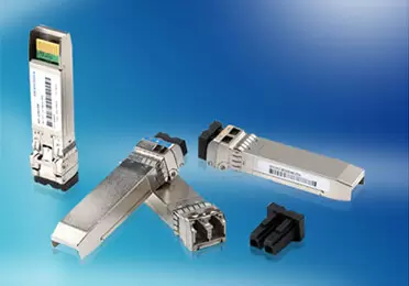
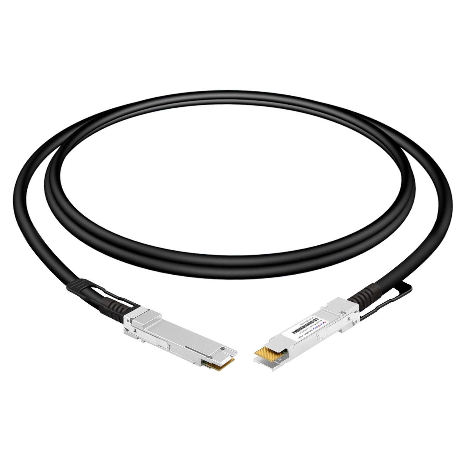
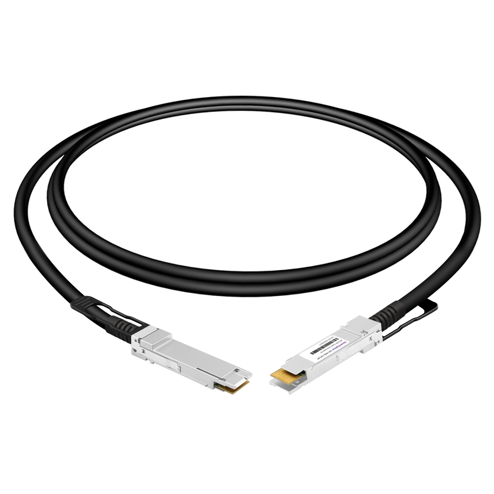
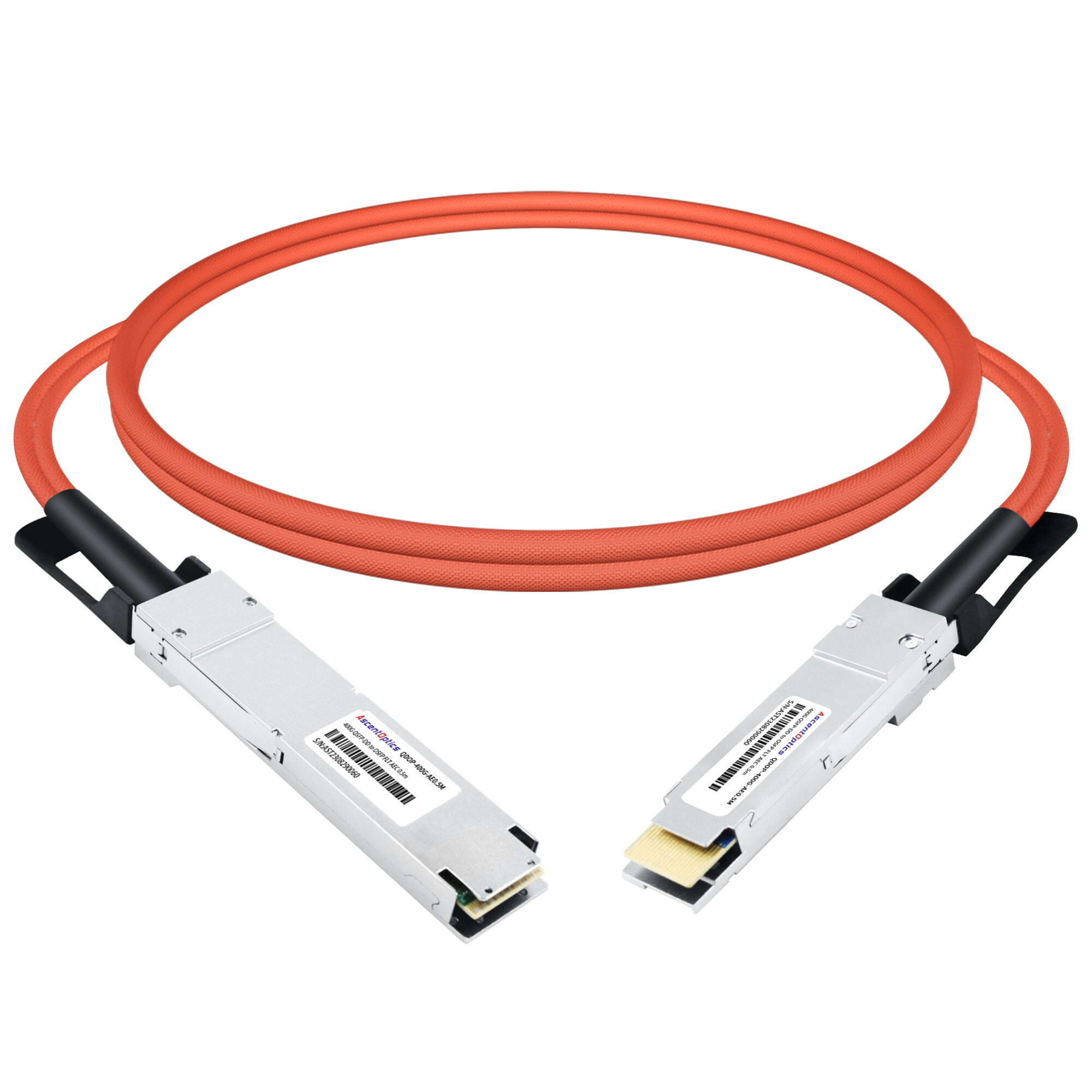
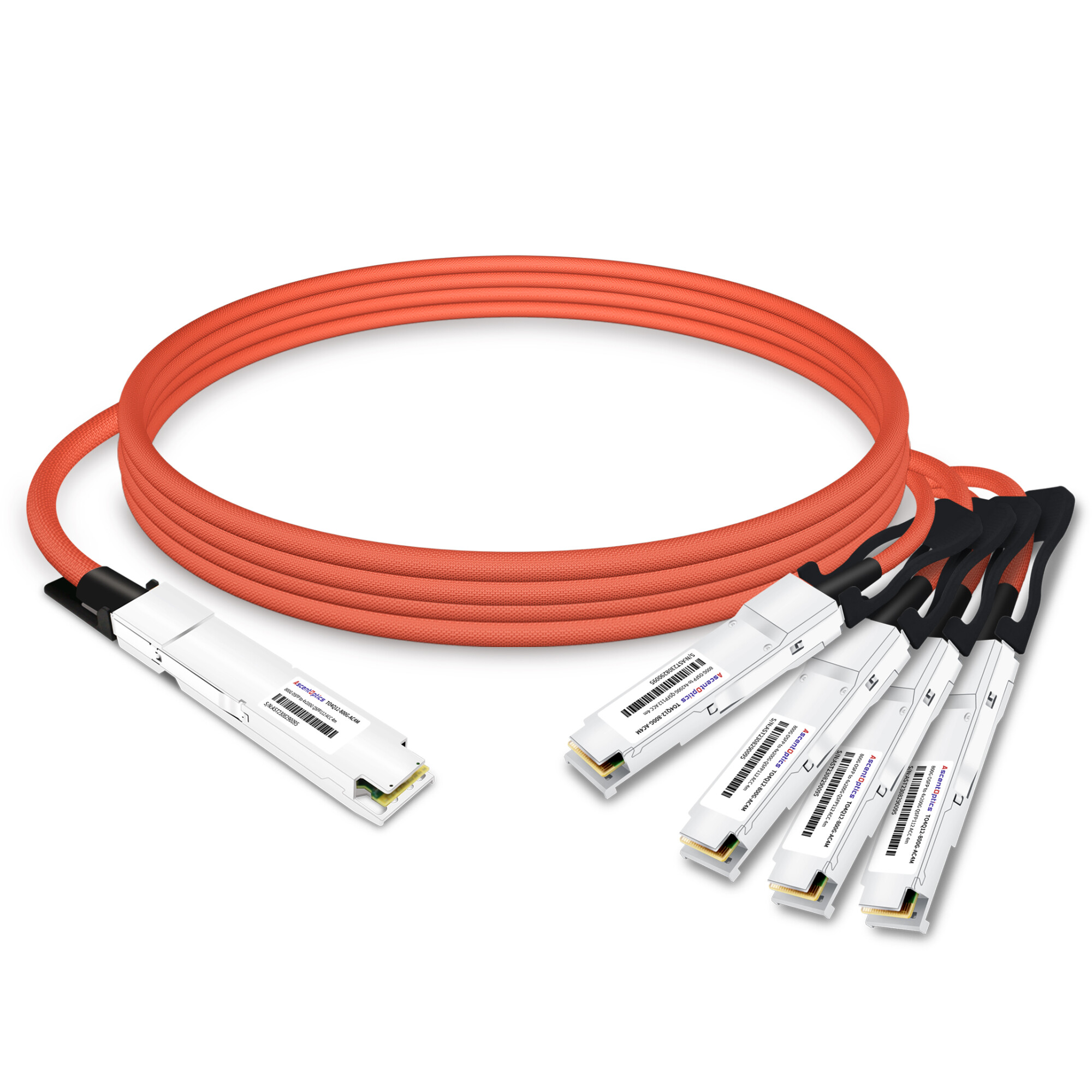
400G DACs are passive or active copper cables designed for short-reach, high-speed interconnects. Available in form factors such as QSFP-DD and OSFP, they offer the advantages of low power consumption and low latency. With specifications covering data rates, wire gauges, lengths, and compatibility, these cables are suitable for connections within and between adjacent racks in data centers.
What Is a 400G DAC Cable?
A 400G DAC (Direct Attach Copper) cable is a fixed-length twinax copper assembly with transceiver modules built into both ends, used to carry 400 Gbps across very short distances inside a rack. A 400G DAC cable can use either eight 50G-class PAM4 lanes or four 100G-class PAM4 lanes, depending on the cable architecture and host interface. These configurations correspond to IEEE 400GBASE-CR8 and 400GBASE-CR4, respectively.
Because the modules are permanently attached, there’s no separate optical transceiver to buy, install, or mismatch. You plug one end into a switch port and the other into a server NIC or a second switch, and the link comes up. That simplicity is the product’s core value, and it’s why DAC cables remain the default choice for in-rack and adjacent-rack connections even as optical modules continue to advance.
The trade-off is reach. Copper attenuates high-frequency signals far faster than fiber does, so a 400G DAC cable is measured in meters, not kilometers. Passive assemblies typically span 0.5 to 3 meters, while active variants with signal-conditioning electronics stretch that to roughly 4 to 9 meters. Beyond that, you’re looking at active optical cables or pluggable transceivers and fiber.
400G DAC Form Factors and Standards
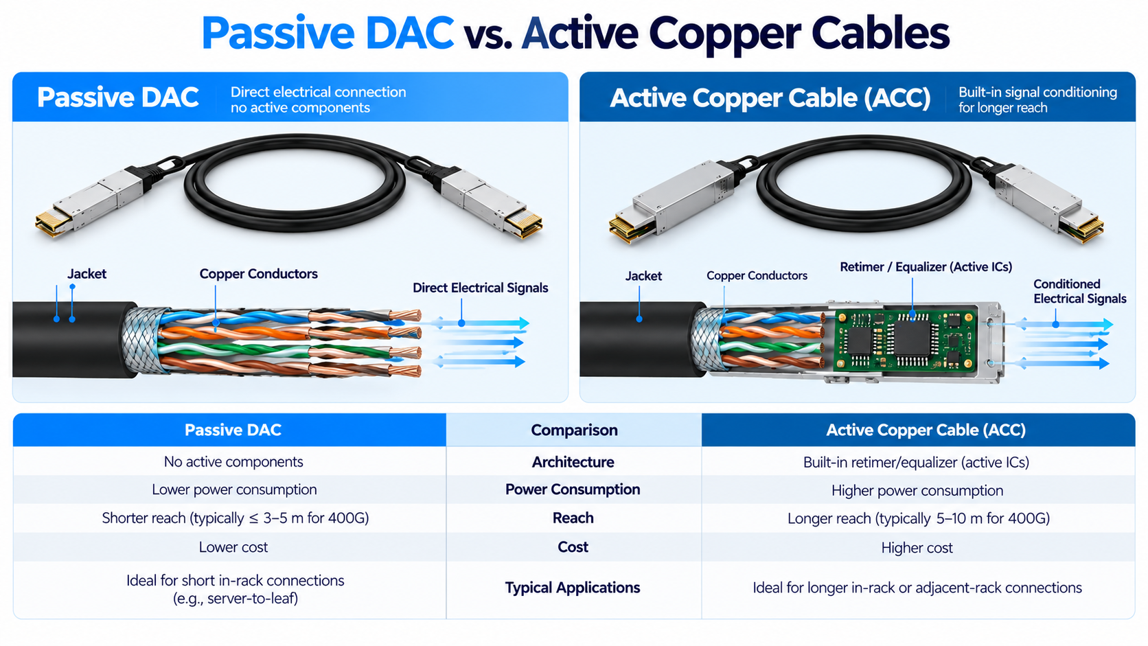
The first specification question is always the connector form factor, because the module on the cable end has to match the port on your equipment. Four form factors dominate the 400G DAC market today.
QSFP-DD (Quad Small Form-factor Pluggable Double Density) is the most widely deployed 400G form factor in Ethernet data centers. It doubles the lane count of the familiar QSFP28 package to eight electrical lanes, which is exactly what an 8x50G PAM4 link needs. QSFP-DD ports are common on ToR and leaf switches from major switching vendors.
OSFP (Octal Small Form-factor Pluggable) is slightly larger than QSFP-DD and was designed from the start with higher power and thermal headroom in mind. It’s the form factor most associated with 400G and 800G ports on platforms aimed at AI and high-performance computing. Because it’s a bit wider, OSFP delivers better airflow and heat dissipation in dense racks.
QSFP112 packs four 100G electrical lanes into a QSFP-sized package, using the newer IEEE 802.3ck signaling. It’s a compact option that’s gaining traction as 100G-per-lane SerDes matures.
OSFP-RHS (Riding Heatsink) refers to an OSFP mechanical configuration designed for use with a host-side riding heatsink. Certain NVIDIA ConnectX-7 network adapters use this interface. Cable selection must account for the specific OSFP mechanical design, port type, and supported electrical signaling.
You’ll also encounter hybrid and breakout assemblies. A hybrid 400G DAC cable might run QSFP-DD on one end and OSFP on the other, useful when a switch and a NIC use different form factors. Breakout cables fan a single 400G port out to multiple slower ports, such as QSFP-DD to four QSFP56 links or eight SFP56 links, which lets one 400G switch port feed several 50G or 100G server ports.
Common 400G breakout configurations include 2 × 200G, 4 × 100G, and, on supported platforms, 8 × 50G. The available breakout modes depend on the switch ASIC, electrical lane architecture, cable design, and endpoint capabilities. A breakout cable does not automatically convert between different SerDes signaling formats.
On the standards side, a compliant 400G DAC references several specifications. IEEE 802.3cd defines 400GBASE-CR8 electrical operation, while 802.3ck covers the 100G-per-lane signaling used by QSFP112 and OSFP-RHS.
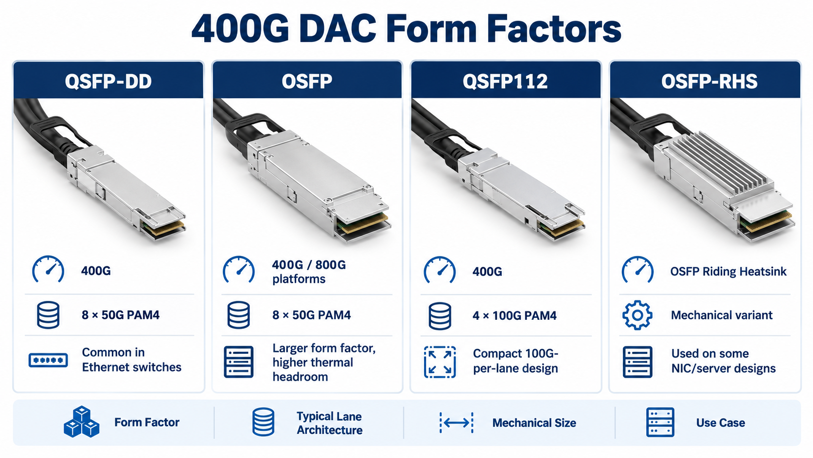
400G DAC Electrical Signaling and FEC Requirements
400G DAC cables use high-speed PAM4 signaling over copper twinax pairs. Depending on the interface architecture, a 400G connection may use eight 50G-class lanes or four 100G-class lanes.
Reliable link establishment requires compatible SerDes signaling, forward error correction (FEC), and PHY configurations at both endpoints. For Ethernet copper PHYs, the applicable IEEE standard defines the required FEC and link-training behavior.
When selecting a 400G DAC cable, verify that both devices support the intended link mode, electrical lane configuration, FEC requirements, and cable assembly. Matching connector form factors alone does not guarantee interoperability.
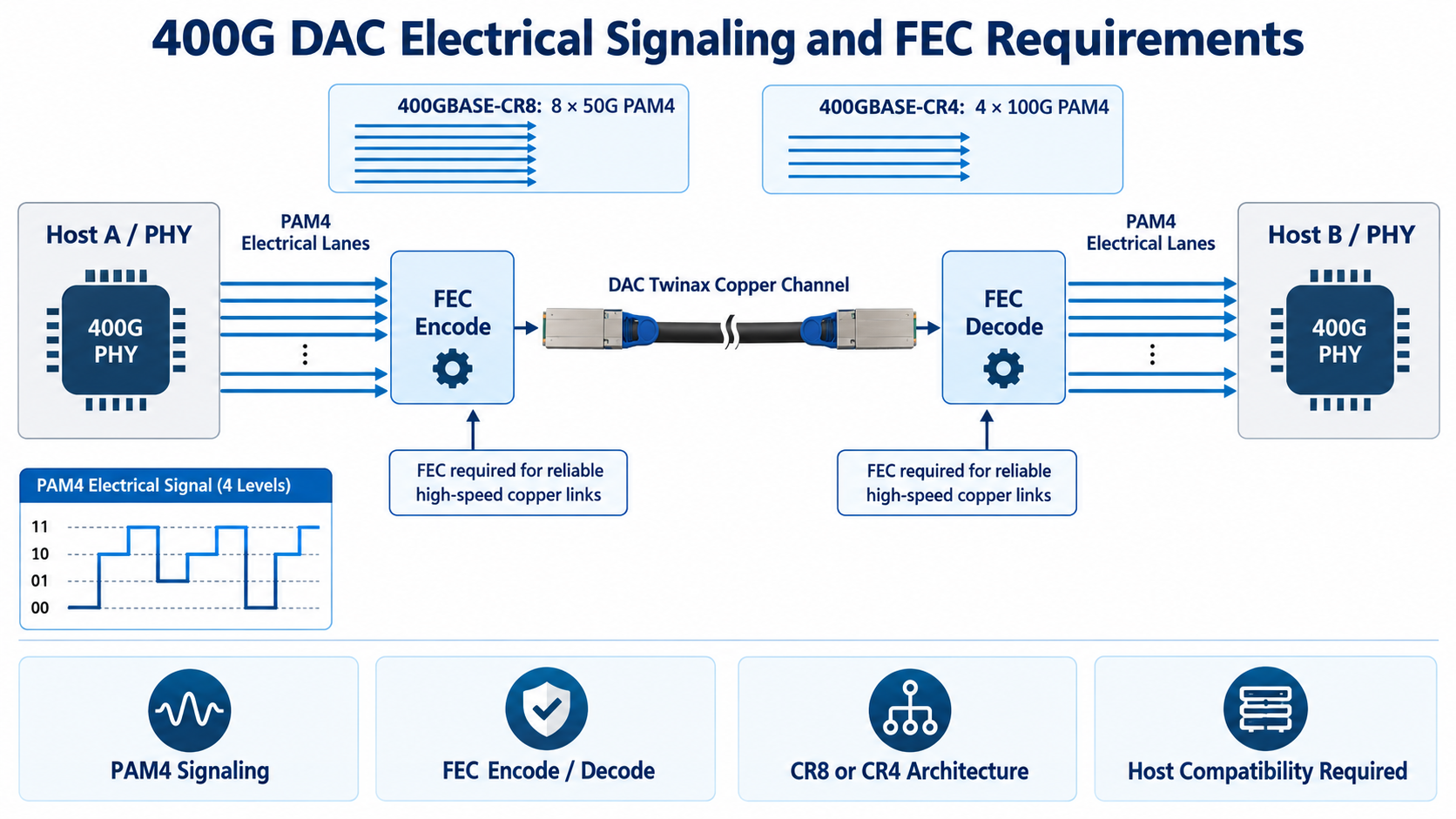
Passive DAC vs. Active Copper Cables: ACC and AEC
Not all 400G copper cables use the same design. Depending on their signal-processing capabilities, they can be categorized into passive DAC, Active Copper Cable (ACC), and Active Electrical Cable (AEC). These options differ in signal integrity, power consumption, latency, and supported reach.
A passive DAC uses twinax copper conductors without active signal-conditioning components. It offers low power consumption, minimal added latency, and cost-effective connectivity for short-distance applications, typically within the same rack. Its supported reach depends on cable construction, wire gauge, and host signal integrity requirements.
Active Copper Cable (ACC)
An ACC integrates active signal-conditioning components, typically redrivers or equalizers, within the cable connectors. These components compensate for signal attenuation and help maintain signal integrity over longer copper connections.
Unlike retimer-based solutions, conventional ACCs generally do not perform full clock and data recovery (CDR). They typically consume less power and introduce less processing latency than retimer-based AECs, although actual performance depends on the design.
An AEC typically incorporates retimers or DSP-based signal-processing components to recover, reshape, and retransmit high-speed electrical signals. This approach improves signal integrity and can support longer copper links than passive DACs or conventional ACCs.
However, the additional signal processing generally results in higher power consumption and latency compared with simpler copper cable designs. The supported reach varies by product and host platform.
Which Type Should You Choose?
Passive DAC is generally preferred for the shortest, lowest-power connections. ACC provides an intermediate option when additional signal conditioning is needed, while retimer-based AEC is suitable for applications requiring stronger signal regeneration or extended copper reach.
For 400G deployments, always verify the cable’s supported length, electrical lane configuration, power requirements, and compatibility with both connected devices.
400G DAC vs AOC vs ACC vs AEC
To choose well, you need the whole interconnect family on one table. Here’s how a 400G DAC cable compares with its optical and active-copper cousins.
| Feature |
Passive DAC |
ACC |
AEC |
| Signal Processing |
None |
Redriver / Equalization |
Retimer / DSP |
| Clock Recovery |
No |
Generally No |
Typically Yes |
| Power Consumption |
Lowest |
Low to Moderate |
Typically Higher |
| Added Latency |
Minimal |
Very Low |
Higher due to retiming |
| Reach |
Short |
Extended Short Reach |
Potentially Longer |
| Cost |
Lowest |
Moderate |
Typically Higher |
The decision almost always comes down to distance, and secondarily to power and manageability. Here’s the framework most network engineers settle on:
- Up to 3–5 meters: passive DAC. It’s the cheapest, lowest-power, lowest-latency option.
- 5–7 meters: ACC or AEC. Active copper buys you extra reach without jumping to optics.
- 7–100 meters: Fiber’s immunity to EMI and its light, flexible cabling pay off beyond the rack.
- Beyond 100 meters: pluggable optical transceivers with structured fiber.
How to Choose a 400G DAC Cable: 7 Factors
Here’s a checklist you can run against any quote or part number before you buy.
- 1. Form factor and port match. Confirm the exact connector on both ends, QSFP-DD, OSFP, QSFP112, or OSFP-RHS, and whether you need a hybrid or breakout configuration. A mismatch here is the most common and most avoidable deployment failure.
- 2. Reach and wire gauge. Measure the actual cable path, including vertical drops and service loops, and leave a small margin. Remember that gauge and length trade against each other: longer passive runs need thicker, stiffer wire.
- 3. Passive vs active. Apply the distance framework above. If you’re near the passive ceiling, an active assembly may be cheaper than the rework of a failed link.
- 4. Compatibility and CMIS coding. Verify the cable’s identification data, management interface, vendor coding, and available diagnostic capabilities. Passive DAC assemblies generally provide limited monitoring compared with active cables and optical transceivers.
- 5. Breakout requirements. If you’re fanning a 400G port to multiple 50G or 100G ports, confirm the breakout mapping matches your NIC and switch port groups.
- 6. Airflow and bend radius. Copper has a minimum bend radius, typically around 65 mm depending on gauge. Tight turns can damage the cable and introduce signal errors that force FEC corrections. Plan cable routing so the copper doesn’t obstruct switch airflow.
400G DAC in AI and Hyperscale Data Centers
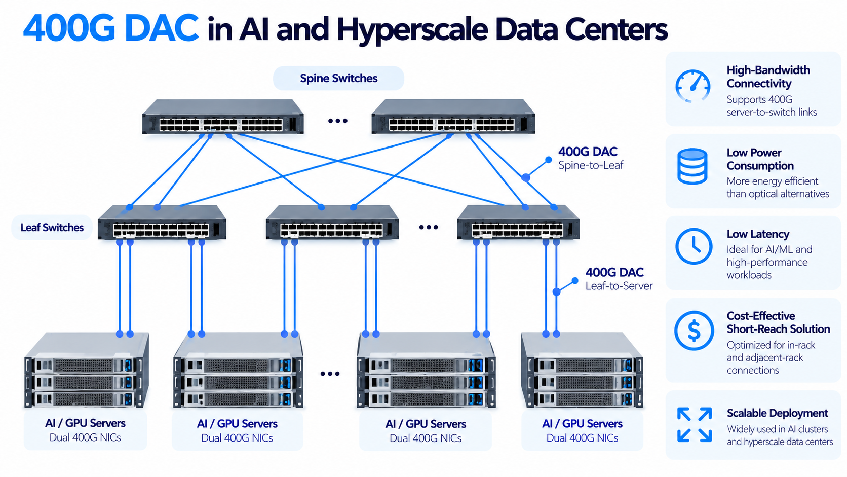
In AI and high-performance computing environments, 400G DAC cables are commonly used for short connections between network adapters and Ethernet or InfiniBand switches. They can provide cost-effective, low-power connectivity for scale-out networking, while internal GPU interconnects may use separate technologies such as NVLink.
Consider a typical AI rack. Eight GPU servers connect to a top-of-rack switch over short, high-bandwidth links. These links carry enormous east-west traffic during training, where data shuttles constantly between GPUs, memory, and the network.
Latency matters, power matters, and cost scales across thousands of identical racks. That’s a near-perfect match for the passive 400G DAC cable profile: sub-3-meter reach, sub-0.15-watt power draw, and the lowest latency available.
400G DAC Cable FAQs
1. What Is the Difference Between 400GBASE-CR8 and 400GBASE-CR4?
400GBASE-CR8 uses eight 50G-class PAM4 lanes, while 400GBASE-CR4 uses four 100G-class PAM4 lanes. Both deliver 400Gbps over copper.
2. What Is the Difference Between QSFP-DD and QSFP112 DAC?
QSFP-DD typically supports 400G through eight 50G PAM4 lanes, while QSFP112 uses four 100G PAM4 lanes. Both can support 400G, depending on the host interface.
3. What Is the Difference Between ACC and AEC?
ACC typically uses redrivers or equalizers to improve signal integrity, while AEC generally uses retimers or DSPs for signal regeneration.
4. Does a 400G DAC Cable Require FEC?
Yes, IEEE 400GBASE-CR8 and 400GBASE-CR4 require FEC. Both endpoints must support the appropriate PHY and FEC configuration.
5. Can a 400G DAC Cable Connect Different Switch Brands?
Yes, if both devices support the cable’s electrical signaling, connector type, and vendor coding requirements. Compatibility testing is recommended.
6. Can a 400G DAC Cable Break Out into Multiple 100G Links?
Yes. Supported 400G ports can use breakout cables for configurations such as 4 × 100G, provided the switch, cable, and connected devices support the required lane mapping.
7. Are 400G DAC Cables Hot-Swappable?
Yes. DAC assemblies use hot-pluggable interfaces, allowing installation or removal without shutting down compatible equipment. Disconnecting an active cable interrupts its link.
8. How Do I Troubleshoot a 400G DAC Link That Is Not Working?
Check connector compatibility, port speed, FEC settings, cable identification, firmware, and breakout configuration. Test with a qualified cable if necessary.
Post Views: 76