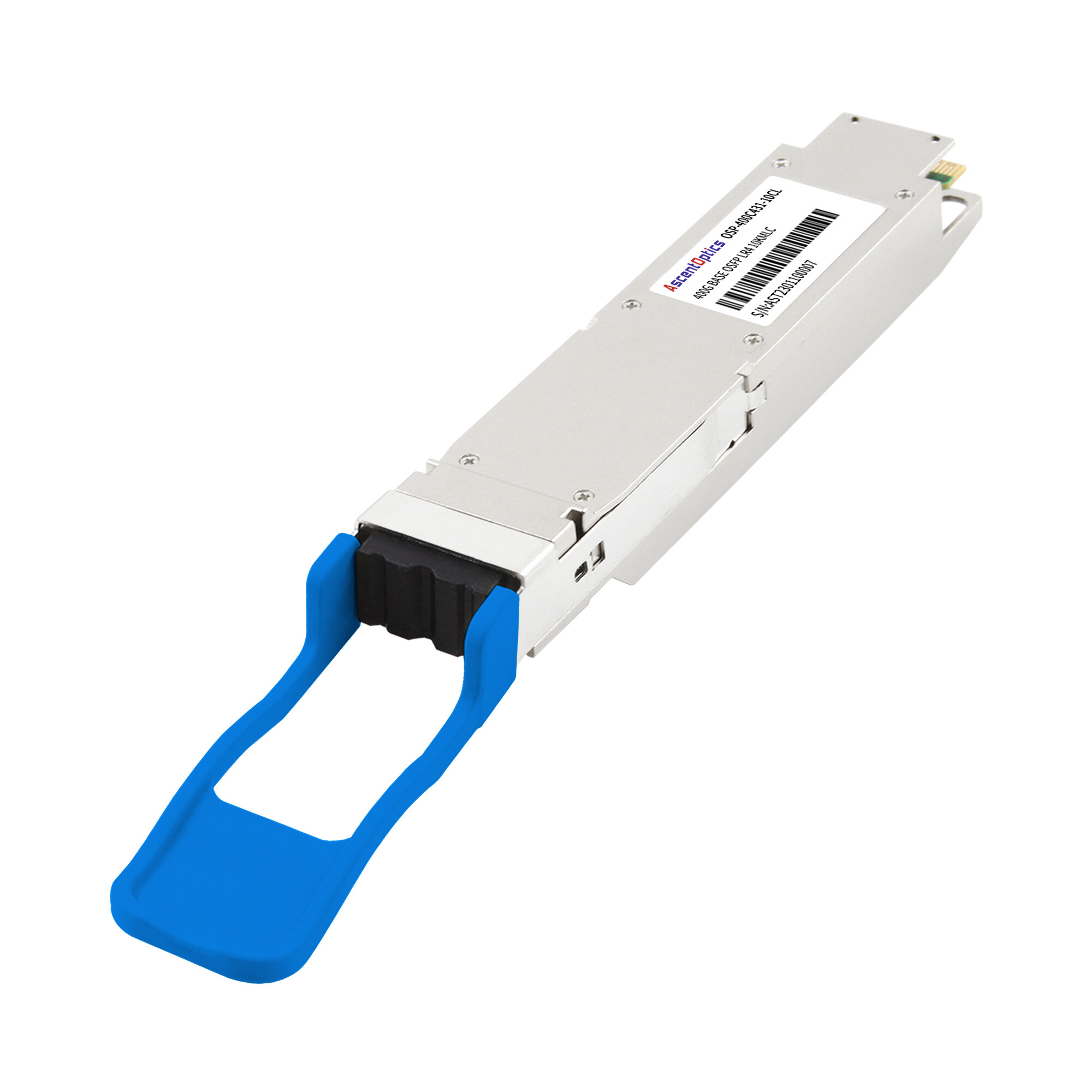
As AI and HPC clusters move toward higher-speed InfiniBand interconnects, optical module power has become an increasingly important consideration in network design. Higher-speed modules can deliver substantially more bandwidth per port, but they also tend to require more electrical power and generate more heat.
For dense AI infrastructure, understanding InfiniBand optical module power helps network architects balance bandwidth, reach, thermal headroom, rack power, and total operating cost.
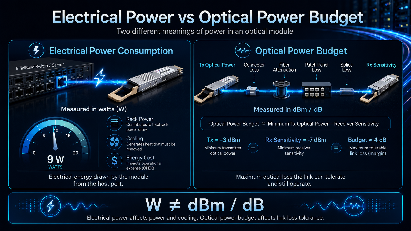
It is also important to distinguish electrical power consumption from optical power budget. Although both use the word “power,” they describe completely different characteristics of an optical link.
What “Power” Means for an InfiniBand Optical Module
Before comparing any numbers, you need to split one word into two definitions. Engineers use “power” in two distinct ways, and mixing them up leads to wrong design decisions.
InfiniBand optical module power consumption is the electrical energy a transceiver draws from the switch port, measured in watts (W). This is the number that matters for your power distribution, your cooling, and your energy bill.
Optical power budget is something else entirely. It is the difference between the transmitter’s output power and the receiver’s minimum sensitivity, measured in decibels relative to one milliwatt (dBm). This number tells you how much fiber and connector loss a link can tolerate before it fails. As data rates increase, optical links generally face tighter loss, signal-quality, and interoperability requirements. Therefore, link design must pay closer attention to connector loss, fiber attenuation, polarity, and overall link margin.
The two are related only in the loosest sense. A module can have a generous optical budget and still draw very little electricity, or the reverse. A network architect must track both, but for different reasons. The rest of this article addresses them in turn, starting with the one that keeps data center operators up at night: the watts.
InfiniBand Optical Module Power Consumption by Generation
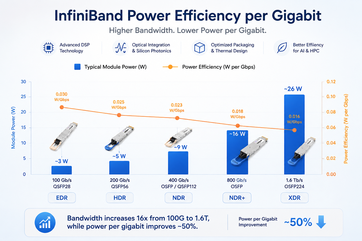
InfiniBand has progressed through a clear set of data rate generations, each with its own form factors and power profile. As speeds climb, per-module power consumption rises, but the efficiency per gigabit actually improves.
| InfiniBand Generation |
Port Speed |
Typical Form Factor |
Typical Optical Module Power* |
| EDR |
100 Gb/s |
QSFP28 |
~2.5–3.5 W |
| HDR |
200 Gb/s |
QSFP56 |
Up to ~5 W |
| NDR |
400 Gb/s |
OSFP / QSFP112 |
Typically up to ~9 W |
| XDR |
800 Gb/s |
OSFP-based |
Vendor/module dependent |
*Actual power consumption varies by optical reach, optical architecture, DSP implementation, temperature, and vendor.
EDR (100 Gb/s, QSFP28) remains common in existing clusters. Short-reach SR4 multimode modules draw roughly 2.5W, while longer-reach LR4 and PSM4 single-mode modules reach about 3.5W. The QSFP28 form factor is compact, and its power draw is modest enough that older switches rarely hit thermal limits because of it.
HDR (200 Gb/s, QSFP56) doubles the lane rate to 50G PAM4 per lane. A 200G QSFP56 SR4 module typically stays under 5W.
NDR (400 Gb/s and 800 Gb/s, OSFP and QSFP112) is the generation now driving most new AI fabrics. A 400G OSFP DR4 module draws under 9W. At 800G, power climbs: an 800G OSFP 2FR4 module reaches about 16.5W, while some 800G QSFP-DD SR8 designs hold to roughly 12W. This is where the DSP chip becomes the dominant power consumer.
XDR (1.6 Tb/s, OSFP224) is the emerging frontier. Early 1.6T modules draw 25W to 26W, enabled by 3nm DSPs and silicon photonics that keep the efficiency per bit moving in the right direction even as absolute wattage rises.
The pattern to remember is straightforward. Raw power goes up with each generation, but power per gigabit keeps falling. That is why a modern 800G port is not four times as hungry as a 200G port, even though it carries four times the bandwidth.
Power Efficiency per Gigabit
Although absolute module power generally increases with each generation, bandwidth efficiency can improve significantly.
For example, a 400G module does not necessarily consume twice the power of a 200G module, and an 800G module does not necessarily consume twice the power of a 400G module.
This improvement comes from advances in semiconductor process nodes, DSP efficiency, optical integration, packaging, and signal-processing architectures.
InfiniBand Optical Power Budget
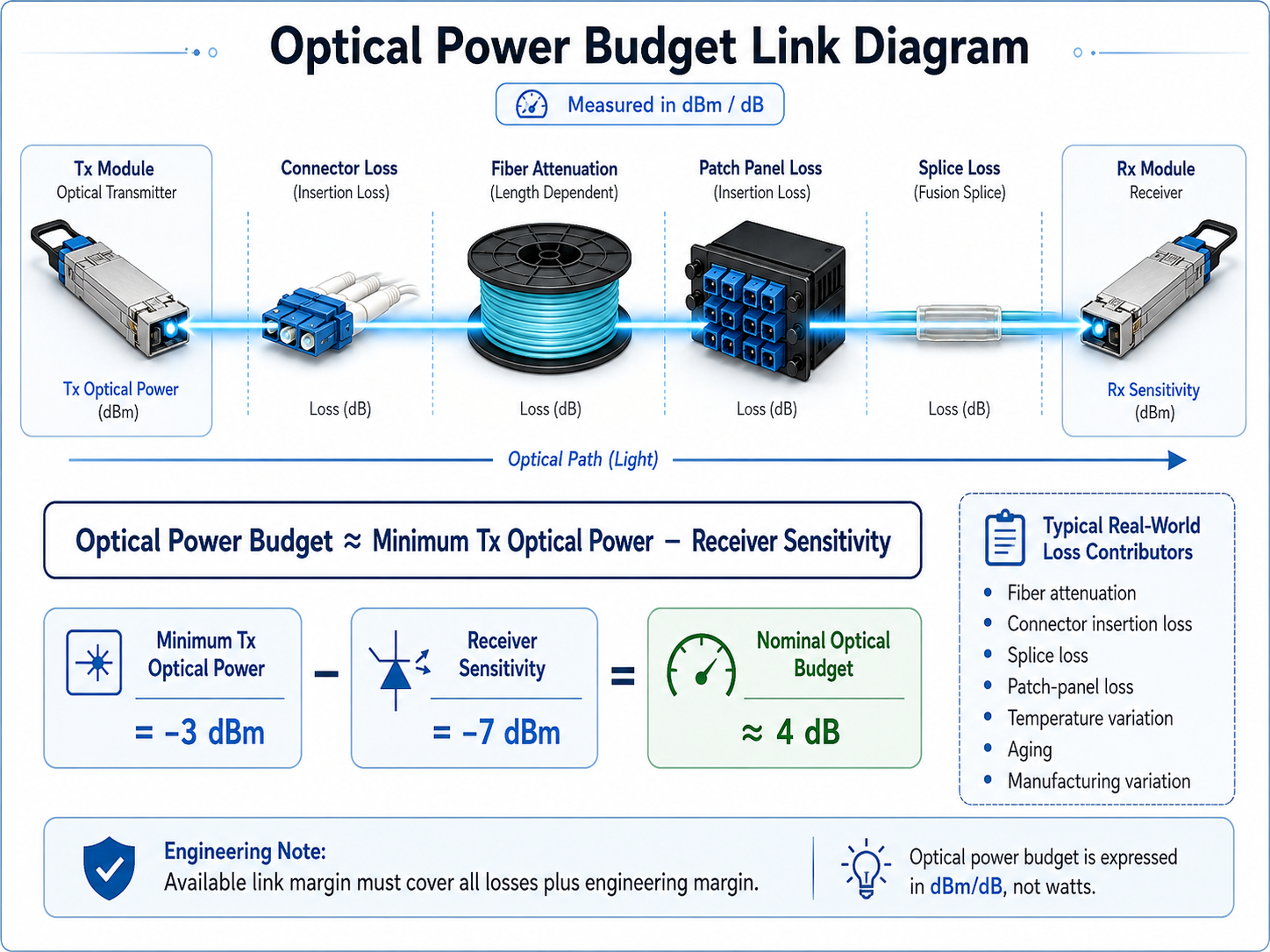
Electrical power consumption is only one aspect of optical module performance. An optical link also has an optical power budget, which determines how much loss the link can tolerate while maintaining the required receiver performance.
A simplified optical budget can be expressed as:
Optical Power Budget ≈ Minimum Tx Optical Power − Receiver Sensitivity
For example, if a transmitter provides a minimum guaranteed output of -3 dBm and the receiver sensitivity is -7 dBm, the resulting nominal optical budget is approximately 4 dB.
In an actual deployment, however, engineers should also reserve sufficient margin for:
- •Fiber attenuation
- •Connector insertion loss
- •Splice loss
- •Patch-panel loss
- •Temperature variation
- •Aging
- •Manufacturing variation
- •Other link impairments
Therefore, the calculated optical budget should not be treated as the amount of loss that can be consumed without any additional engineering margin.
Typical Optical Budget Considerations
| Module |
TX Power |
Optical Budget |
| 100G EDR SR4 (QSFP28, MMF) |
-8.4 to +2.4 dBm |
1.9 dB |
| 400G NDR SR4 (QSFP112, MMF) |
-4.6 to +4.0 dBm |
1.8 dB |
| 800G NDR 2FR4 (OSFP, SMF) |
-3.2 to +4.4 dBm |
4.0 dB |
| 1.6T XDR 2FR4 (OSFP, SMF) |
-2.2 to +4.9 dBm |
4.0 dB |
Short-reach multimode modules carry tight budgets, typically around 2 dB, because they are built for short, clean links. Single-mode FR4 modules reach a 4 dB budget, leaving more room for patch panels and splices on longer runs.
Two details trip up engineers here more than any others. First, higher-speed PAM4 modules have tighter receiver sensitivity requirements than the older NRZ generation, so you have less margin for sloppy cabling. Second, connector polish matters. NDR and XDR modules use MPO/APC angled connectors, while EDR and HDR use MPO/UPC. The two are not interchangeable, and mixing them creates enough return loss to destroy a link margin that looked fine on paper.
InfiniBand vs Ethernet: Where Power Efficiency Differs
InfiniBand and Ethernet can use similar optical technologies, including PAM4 signaling, parallel-fiber architectures, and pluggable optical form factors.
However, optical module compatibility is not determined by data rate or form factor alone.
A module must also support the electrical interface, management requirements, firmware, link training, and platform-specific implementation of the host system. Therefore, an Ethernet-compatible 400G optical module should not automatically be assumed to be interoperable with an InfiniBand HCA or switch.
From a power perspective, the optical architecture and signal-processing implementation are often more important than the protocol name itself.
At the same data rate and reach, optical modules with similar optical engines and DSP architectures can have comparable power characteristics. The overall network power profile, however, also depends on the NIC, switch ASIC, DSP, cable type, and system architecture.
How to Reduce InfiniBand Optical Module Power Consumption
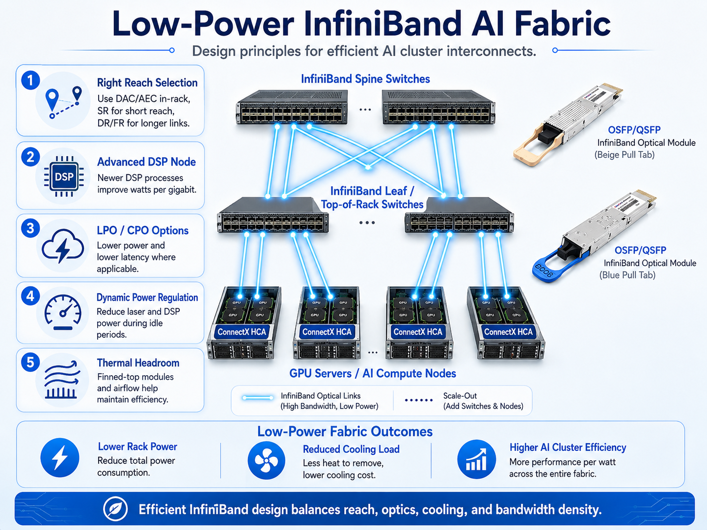
Cutting optical power is a design discipline, not a single purchase decision. These five moves deliver the largest savings in practice.
Match reach to technology. The single biggest mistake is over-provisioning with long-reach optics for short links. Use passive or active copper cables inside a rack, multimode SR optics for links under 100 meters, and reserve single-mode DR or FR optics for longer spans. A 10 km LR4 module burns more power than a 100 m SR4 module, and neither helps if your run is 30 meters.
Choose a newer DSP process node. In PAM4 modules, the DSP is the largest power consumer. A 7nm DSP enables 800G modules around 14W, a reduction of 35 to 40 percent versus older chips, and 3nm DSPs carry 1.6T modules at 25W. When comparing modules, the DSP node is one of the most direct proxies for efficiency.
Adopt LPO and CPO where available. Linear-drive pluggable optics strip out the retiming DSP entirely for short reaches, cutting both power and latency. Co-packaged optics go further by integrating the optical engine with the switch chip, which is why hyperscalers are moving toward CPO for their densest fabrics.
Use dynamic power regulation. Some modern modules can reduce laser and DSP power automatically when a link is idle or underloaded. In a 10,000-GPU cluster with variable utilization, this firmware-level feature alone can save hundreds of thousands of kilowatt-hours per year.
Plan thermal headroom. Finned-top OSFP packages shorten the path from chip to heatsink, preventing temperature-driven power and performance drift in dense racks. Power draw rises with temperature, so cooling design is part of the power equation, not separate from it.
Selecting Low-Power InfiniBand Modules for AI and HPC
When power efficiency is an important design requirement, use a system-level approach rather than selecting modules based on wattage alone.
First, determine the required transmission distance. Then compare module power at the required reach and data rate.
Next, evaluate the module’s DSP and optical architecture, maximum power, thermal characteristics, and host compatibility.
Connector and cabling requirements should also be verified carefully, particularly for high-speed MPO/MTP-based connections.
A practical checklist includes:
- •Required port speed
- •Transmission distance
- •Fiber type
- •Connector and polarity
- •Typical and maximum module power
- •DSP and optical architecture
- •Operating temperature
- •Thermal requirements
- •Host platform compatibility
- •Optical link budget and engineering margin
The goal is not simply to choose the module with the lowest wattage. The better approach is to select the module that provides the required bandwidth and reach with an appropriate combination of power efficiency, optical margin, thermal performance, and reliability.
Conclusion
InfiniBand optical module power comes down to two numbers you must track separately. Electrical power consumption rises from about 2.5W at 100G EDR to 26W at 1.6T XDR, but efficiency per gigabit keeps improving with each DSP generation. Optical power budget, measured in dBm, tells you how much link loss a module can tolerate, and it shrinks as PAM4 signaling tightens receiver sensitivity.
The levers that reduce power are the same ones that future-proof a fabric: match reach to technology, prefer newer DSP nodes, adopt LPO and CPO where they fit, use dynamic power regulation, and design for thermal headroom. None of this is exotic. It is simply the difference between treating optics as a commodity and treating them as part of your power architecture.
Frequently Asked Questions (FAQ)
1. What is InfiniBand optical module power consumption?
It is the electrical power an optical module draws from the host port, measured in watts (W). It affects rack power, cooling requirements, and operating costs.
2. How much power does an InfiniBand optical module consume?
Power consumption varies by generation, data rate, reach, and module design. Representative values range from about 2.5 W for some 100G EDR modules to higher levels for 400G NDR and 800G XDR modules.
3. What is the difference between optical power consumption and optical power budget?
Power consumption refers to electrical energy used by the module and is measured in watts. Optical power budget refers to the amount of optical link loss that can be tolerated and is measured in decibels (dB).
4. Does a higher-speed InfiniBand module always consume more power?
Not necessarily in direct proportion to bandwidth. Higher-speed modules generally consume more absolute power, but advances in DSPs, optical engines, and semiconductor technology can improve power efficiency per gigabit.
5. How can I reduce InfiniBand optical module power consumption?
Choose the appropriate transmission reach, compare typical and maximum power consumption, consider efficient DSP and optical architectures, and ensure adequate thermal management.
6. Why is optical link budget important for InfiniBand networks?
The optical power budget determines how much loss a link can tolerate. Fiber attenuation, connector loss, and other impairments must remain within the available budget with sufficient engineering margin.
7. Are InfiniBand and Ethernet optical modules interchangeable?
Not automatically. Although they may use similar optical technologies and form factors, compatibility also depends on the host electrical interface, firmware, management requirements, and platform implementation.
8. Can LPO and CPO reduce InfiniBand optical power consumption?
LPO and CPO can potentially improve power efficiency by reducing electrical signal-processing overhead. Their suitability depends on the specific system architecture, host interface, and deployment requirements.
Post Views: 115