In a fully loaded 32-port 400G switch, the optical transceivers can consume more power than the switch chassis itself. This is the reality network engineers face when planning dense QSFP112 deployments, yet most datasheets only list a single power number that hides the real thermal story.
You already know that power and cooling dominate modern data center operating costs. What you need is a practical way to size QSFP112 power consumption by module type, calculate rack-level thermal load, and compare form factors without wading through scattered vendor specifications.
This guide breaks down QSFP112 power consumption into actionable numbers. You will learn how much power each module variant draws, how QSFP112 compares to QSFP-DD and OSFP, how to calculate switch and rack thermal budgets, and where Linear Pluggable Optics (LPO) can reduce energy use. If you are evaluating what QSFP112 is for your next upgrade, this article gives you the thermal foundation to make the right choice.
What Is QSFP112?
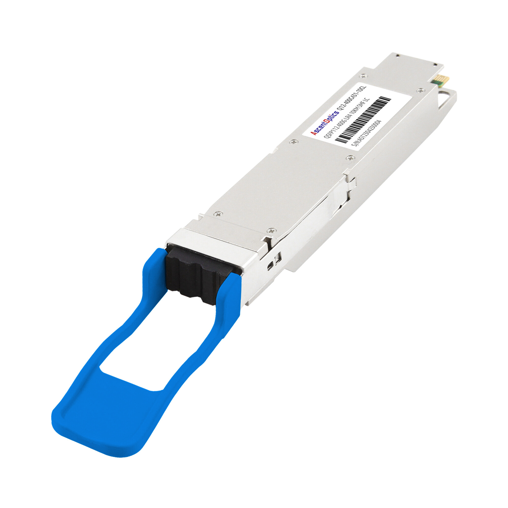
QSFP112 is a quad small form-factor pluggable optical transceiver module that delivers 400 Gbps over four electrical lanes operating at 112 Gbps each. The electrical interface uses 112G PAM4 signaling as defined in IEEE 802.3ck, enabling 400G throughput in the same physical package as QSFP28 and QSFP56 modules.
The module retains the classic QSFP dimensions of approximately 18.4 mm by 89.4 mm by 8.5 mm. This backward-compatible form factor lets data centers upgrade from 100G or 200G to 400G without changing switch faceplates or cable infrastructure, provided the host ASIC supports 112G PAM4 SerDes.
Because QSFP112 uses four lanes rather than the eight lanes required by QSFP-DD, it reduces SerDes complexity, printed circuit board trace count, and overall power draw. These characteristics make it an attractive option for hyperscale data centers, AI clusters, and enterprise networks that need 400G density without the thermal penalty of larger form factors.
QSFP112 Power Consumption by Module Type
QSFP112 power consumption varies significantly based on reach, optical technology, and whether the module uses a digital signal processor (DSP). Treating all QSFP112 modules as identical will lead to under-provisioned power distribution units and overloaded cooling systems.
Optical Transceiver Modules
The table below summarizes typical maximum power draw for common QSFP112 optical transceiver variants.
| QSFP112 Variant |
Reach
|
Fiber Type |
Typical Max Power
|
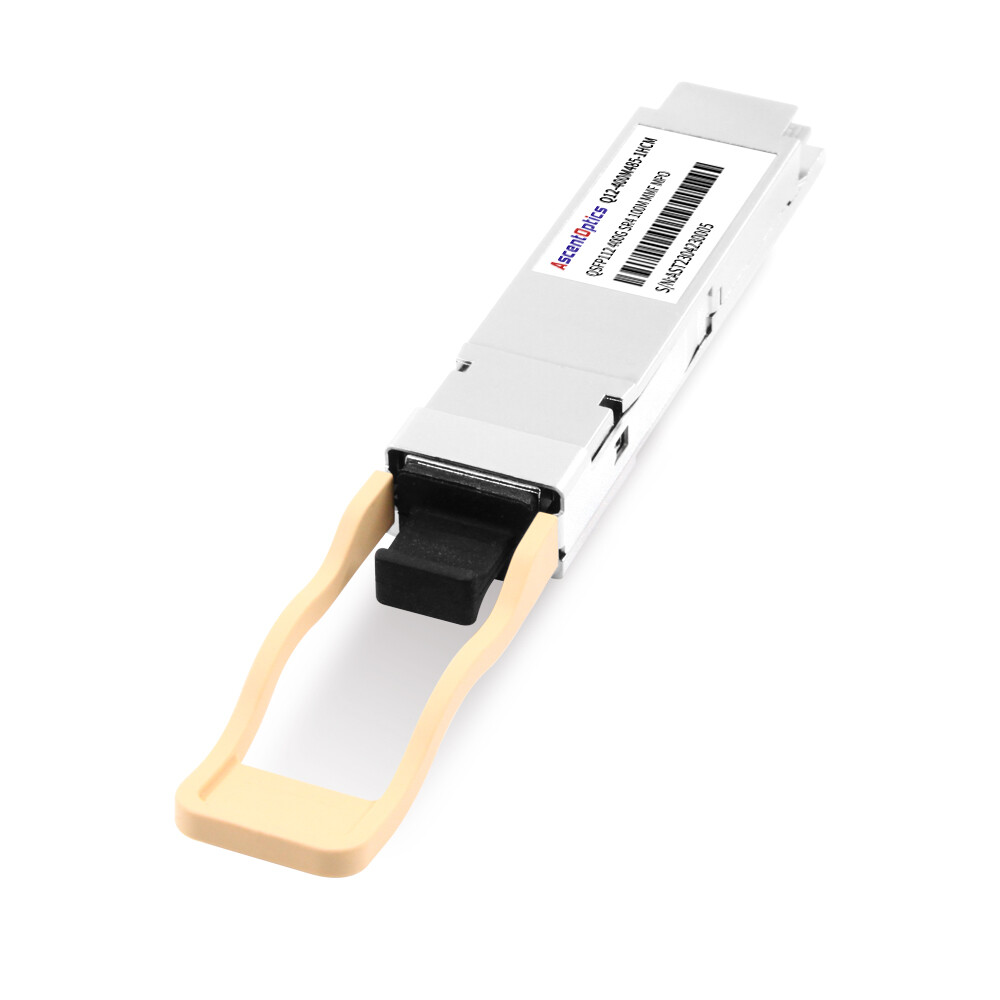
| SR4 |
Up to 100 m
|
Multimode (OM4/OM5) |
~8 W
|
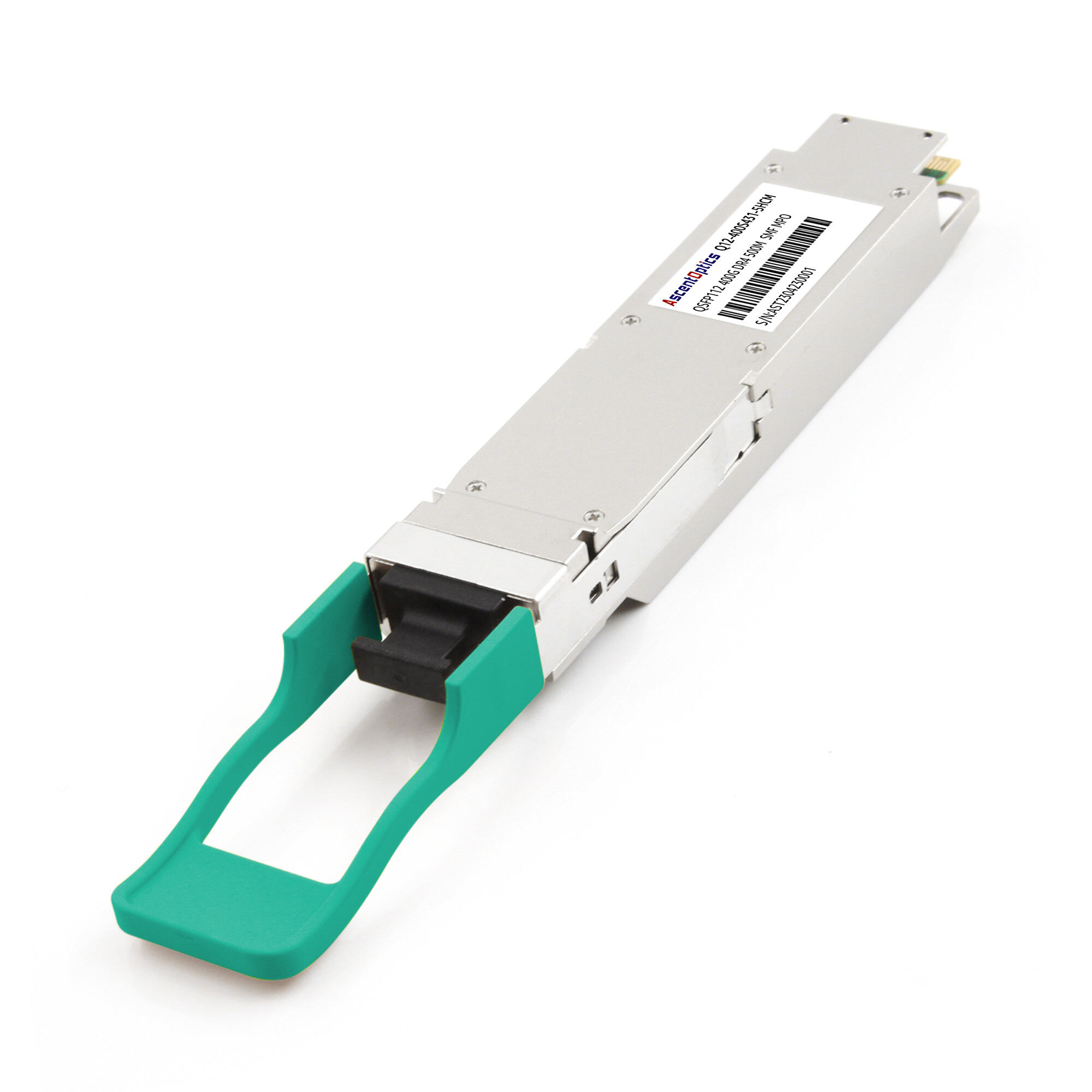
| DR4 |
Up to 500 m
|
Single-mode |
~10 W
|
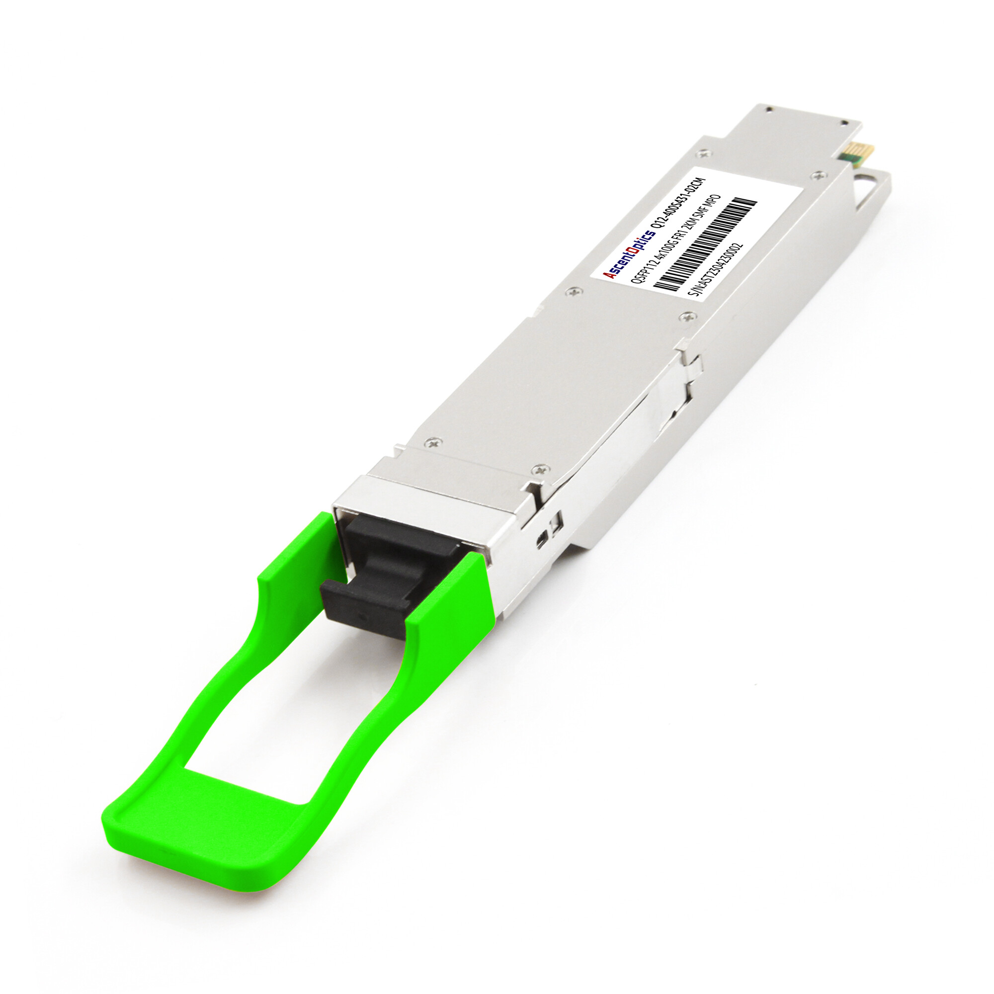
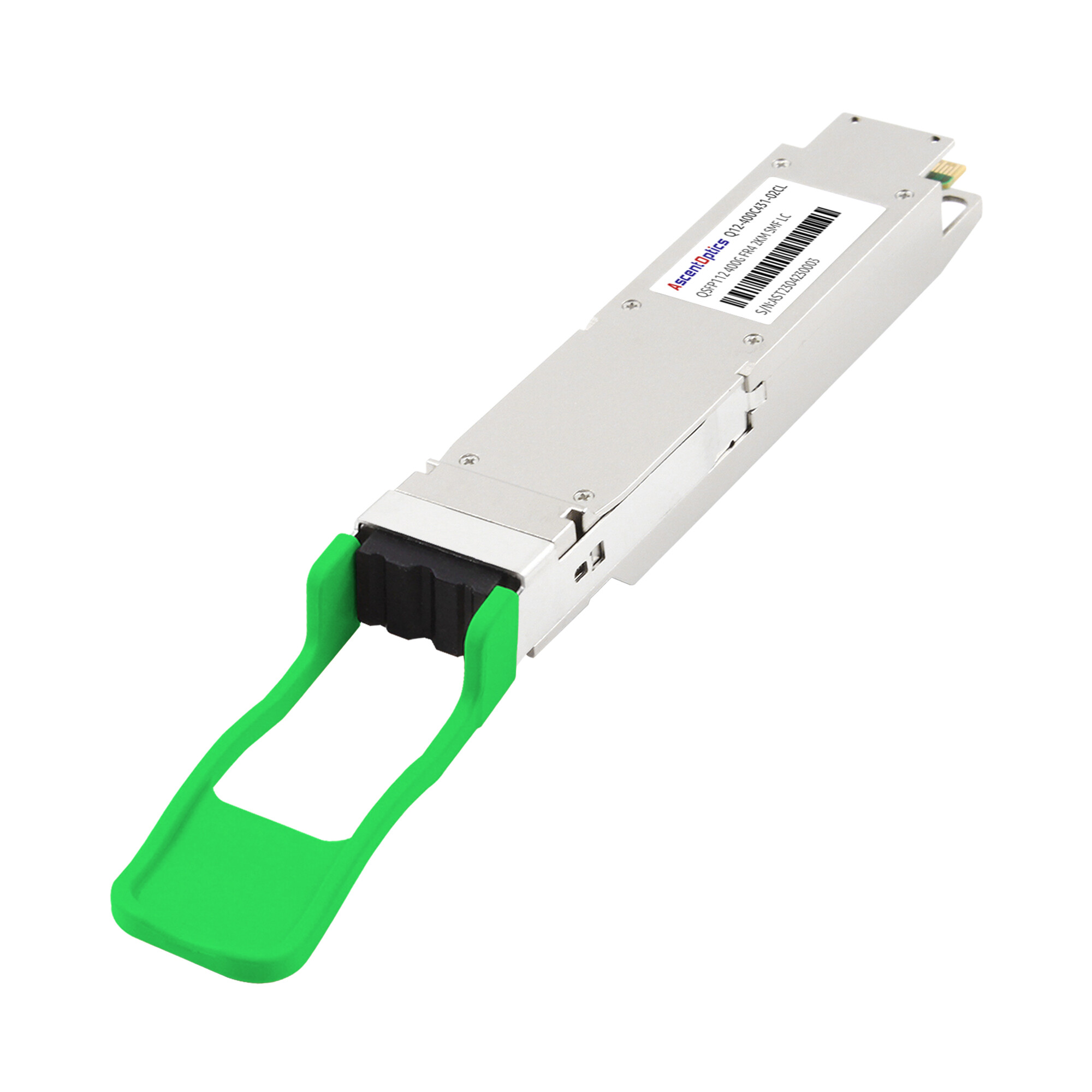
| FR4 |
Up to 2 km
|
Single-mode |
~9.5–12 W
|
| LR4 |
Up to 10 km
|
Single-mode |
~12 W
|
Short-reach multimode modules such as SR4 consume the least power because they use simpler vertical-cavity surface-emitting laser (VCSEL) arrays and PIN photodetectors. Longer-reach single-mode modules require more complex optics and DSP-based equalization, which pushes power toward the upper end of the range.
When Marcus Chen’s team deployed 400G spine switches last year, they assumed every QSFP112 module would draw 8 W. They sized their rack PDUs accordingly. Two months after go-live, thermal alarms appeared during peak traffic. The root cause: the deployment used FR4 modules for data center interconnects, and those modules were drawing 11 W each. That 3 W per-module gap translated to nearly 100 W of unexpected heat in every fully loaded switch. The lesson: always use the highest-power variant in your thermal calculations, not the lowest.
Passive and Active Cables
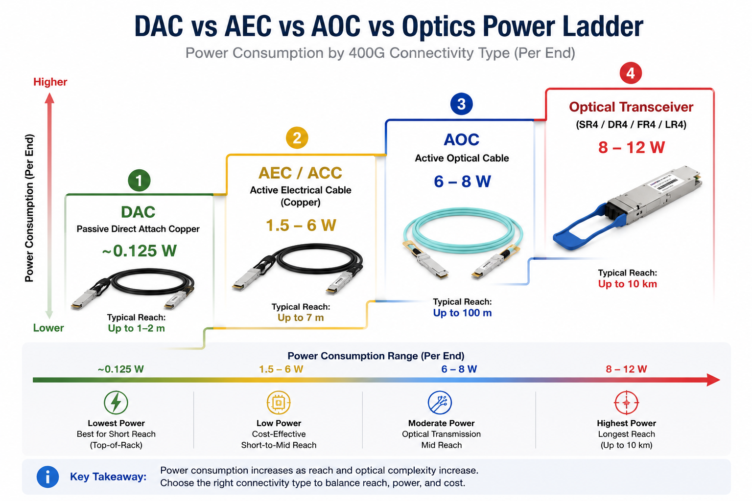
Cable assemblies based on the QSFP112 form factor draw substantially less power than optical transceivers. For short-reach connections within a rack or between adjacent racks, cables often represent the most power-efficient choice.
| Cable Type |
Typical Power per End |
Typical Reach |
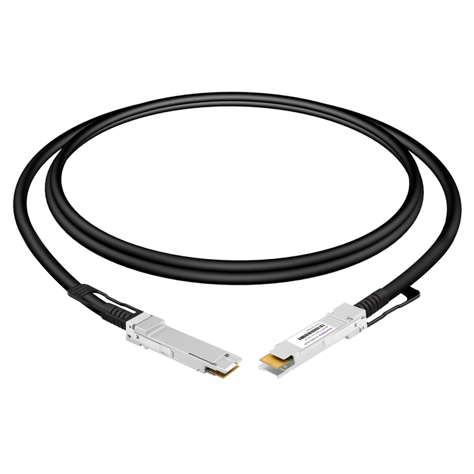
| Passive DAC |
~0.125 W |
Up to 1–2 m |
| Active ACC/AEC |
~1.5–6 W |
Up to 7 m |
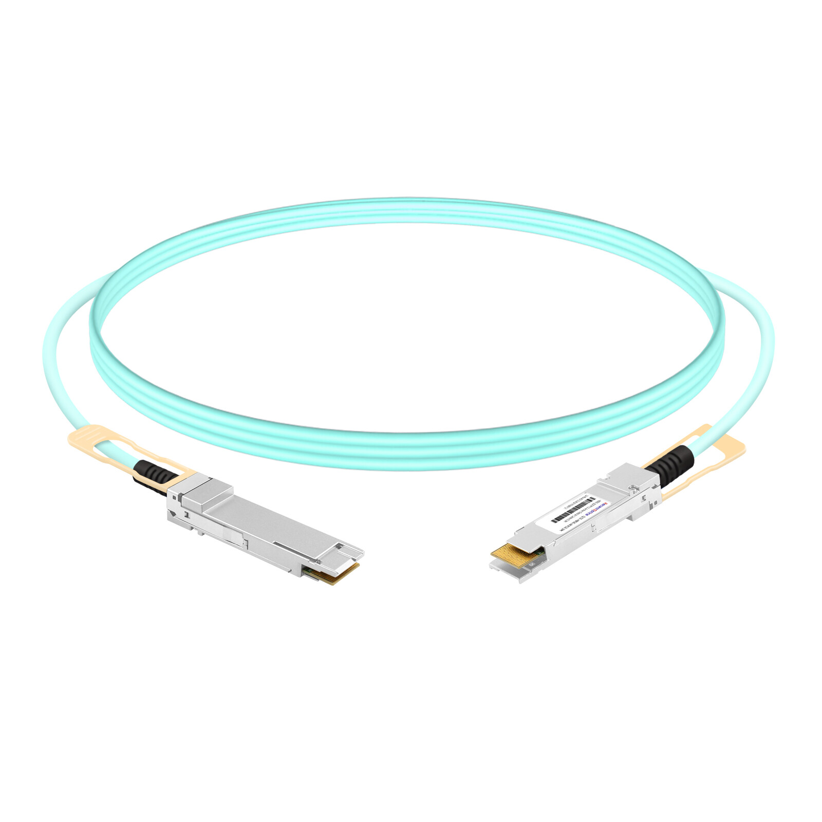
| Active AOC |
~6–8 W |
Up to 100 m |
Passive direct attach copper (DAC) cables use almost no power because they contain no active electronics. Active electrical cables (AEC/ACC) add redriver or retimer chips to extend reach, which increases power consumption but still remains below optical transceiver levels. Active optical cables (AOC) convert electrical signals to optical transmission and therefore approach the power draw of SR4 transceivers.
Linear Pluggable Optics (LPO) Variants
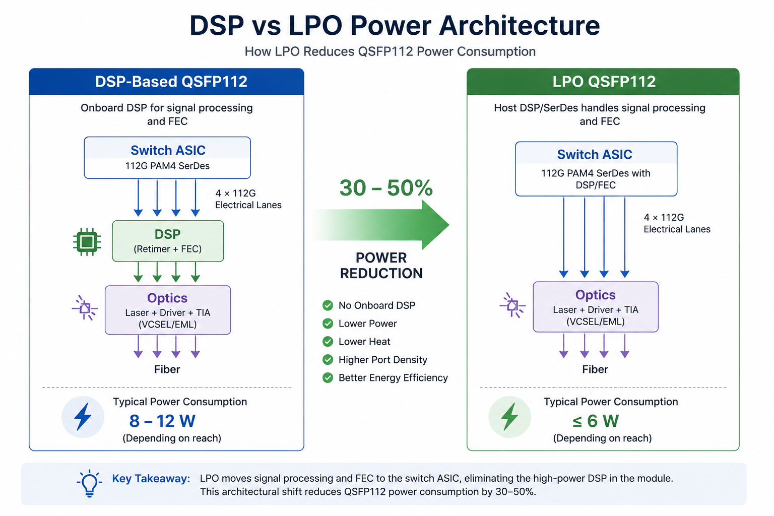
LPO modules remove the onboard DSP and shift equalization and forward error correction (FEC) to the host switch ASIC. This architectural change cuts power dramatically.
Typical QSFP112 LPO specifications list maximum power consumption of 6 W or less, representing approximately 20–40% reduction compared with fully retimed DSP-based designs. The trade-off is that LPO modules require host switches with capable 112G SerDes and are generally limited to shorter reaches, commonly up to 500 m or 2 km, depending on implementation.
For large-scale deployments where every watt matters, LPO is becoming an increasingly practical option. The savings compound quickly. Across a 32-port switch, moving from 10 W DSP modules to 6 W LPO modules removes 128 W of heat before accounting for reduced cooling load.
How QSFP112 Power Compares to Other 400G Form Factors
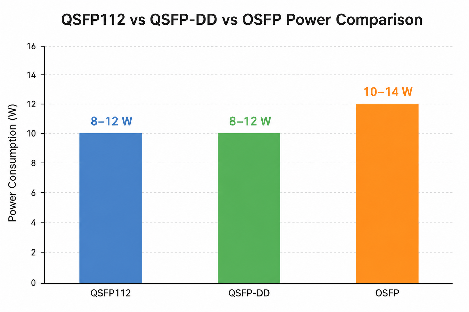
Understanding QSFP112 power consumption requires context. The table below compares 400G form factors on a per-module basis and on a per-Gbps efficiency basis.
| Form Factor |
Typical Module Power |
Power per Gbps |
32-Port Optical Power |
| QSFP112 |
8–12 W |
~20–30 mW/Gbps |
256–384 W |
| QSFP-DD |
8–12W |
~25–35 mW/Gbps |
320–448 W |
| OSFP |
10–14W |
~30–40 mW/Gbps |
384–512 W |
QSFP112 generally consumes 2–4 W less per module than QSFP-DD and 4–6 W less than OSFP for equivalent 400G connectivity. On a per-bit basis, this translates to roughly 20–30 mW per Gbps for QSFP112 compared with 25–35 mW per Gbps for QSFP-DD. QSFP112 modules can offer lower system-level power consumption when paired with native 112G SerDes platforms. However, actual module power depends largely on optical architecture, DSP implementation, and reach requirements rather than form factor alone. Actual power consumption is driven more by optical design and DSP architecture than by form factor alone.
For a detailed comparison of packaging and migration considerations, see our complete QSFP-DD vs QSFP112 guide. If you are also evaluating 100G baseline power, our QSFP28 power consumption guide provides comparable thermal planning data.
QSFP112 Thermal Specifications and Operating Temperature
The QSFP112 Multi-Source Agreement (MSA) defines thermal operating classes to ensure interoperability across different network environments. Understanding these classes helps you select the right module grade and avoid thermal failures in challenging deployments.
MSA Temperature Classes
| Temperature Class |
Case Temperature Range |
Typical Use Case |
| Standard (Commercial) |
0°C to +70°C |
Enterprise and data center |
| Extended |
-5°C to +85°C |
Less controlled environments |
| Industrial |
-40°C to +85°C |
Outdoor or telecom applications |
Most data center deployments use standard commercial-grade modules rated for 0°C to +70°C. Extended and industrial grades are available for telecom huts, edge locations, and other environments where ambient temperatures fluctuate more widely.
The MSA also defines application subclasses with tighter functional ranges. Class A1 restricts operation to 15°C–60°C, while Class A4 extends the upper limit to 75°C. These subclasses help switch vendors design thermal solutions for specific deployment scenarios.
Why Thermal Design Matters at the Rack
QSFP112 modules rely on conduction from the module body through the switch cage to the switch heatsink. The flat-top thermal design maximizes contact area, but the module still depends on adequate airflow across the faceplate.
In belly-to-belly rack configurations, exhaust from one switch row becomes intake air for the opposite row. Intake temperatures can rise 10°C to 15°C above ambient, which reduces the thermal margin available to each module. If your data center operates near the upper end of the commercial range, extended-temperature modules or improved airflow management may be necessary.
Rack-Level Power and Cooling Calculations
Sizing a QSFP112 deployment requires moving from module-level specifications to rack-level power and cooling budgets. The calculation is straightforward, but the inputs must reflect worst-case rather than typical conditions.
Basic Optical Power Formula
Use the following formula to estimate optical power for a switch:
Optical power (W) = Number of ports × Module TDP
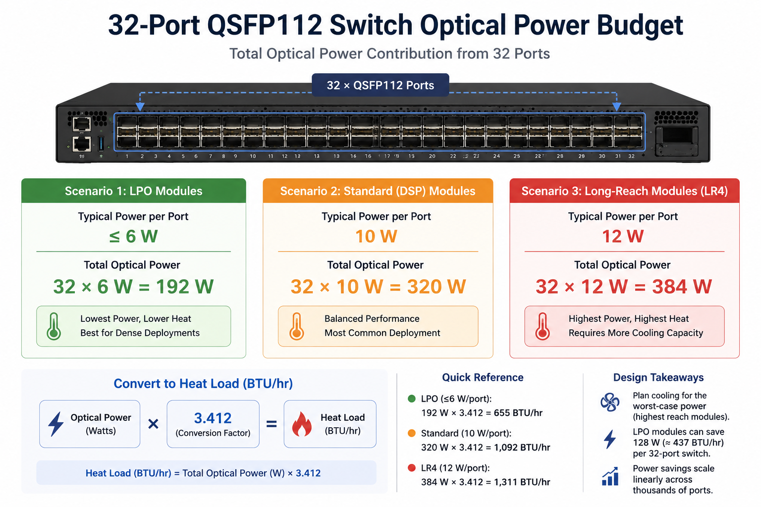
For a 32-port 400G switch fully populated with QSFP112 modules:
| Scenario |
Module TDP |
Optical Power |
| Best case (LPO) |
6 W |
192 W |
| Typical mixed reach |
10 W |
320 W |
| Worst case (long-reach) |
12 W |
384 W |
These numbers represent optical power only. You must add the switch base power, which includes the ASIC, fans, power supplies, and management controllers.
Real-World Switch Power Examples
The following table shows published system-level power for several 32-port 400G QSFP112 switches.
| Switch |
Ports |
Rated System Power |
Airflow |
| Hohunet S8532-EI |
32×400G QSFP112 |
307 W typical / 383 W max |
264 CFM |
| Arista DCS-7060DX5-32 |
32×400G QSFP112 |
~550 W |
Front-to-rear |
| Maipu NSS7816-32QE |
32×400G QSFP112 |
823–937 W |
Direction dependent |
These figures show that system power varies significantly by vendor and platform architecture. Always consult the specific switch datasheet rather than applying generic estimates.
Converting Power to Cooling Load
Every watt consumed eventually becomes heat. To convert electrical power into cooling load, multiply total watts by 3.412 to obtain BTU per hour.
Cooling load (BTU/hr) = Total power (W) × 3.412
For example, a rack with ten Hohunet S8532-EI switches running at 383 W each produces approximately 13,078 BTU/hr per switch, or 130,780 BTU/hr for the full rack. Cooling infrastructure and PDU sizing should include a 20% headroom above this calculated load to accommodate future expansion and transient thermal events.
If you are planning a broader QSFP112 rollout, our QSFP112 data center deployment guide covers switch selection, cabling, and migration planning in more detail.
LPO vs DSP: How Architecture Affects QSFP112 Power
The choice between DSP-based and LPO QSFP112 modules is one of the most important power decisions in a 400G deployment. The two architectures solve the same problem with different trade-offs.
DSP-Based QSFP112 Modules
Fully retimed QSFP112 modules include an onboard DSP that handles equalization, clock data recovery, and FEC. This makes them compatible with a wide range of host switch ASICs and enables longer reaches.
Typical power consumption: 8–12 W
DSP modules are the safe default when the switch ASIC SerDes quality is unknown or when you need to reach beyond 2 km. They also simplify interoperability because the module handles most of the signal processing independently of the host.
LPO QSFP112 Modules
LPO modules eliminate the onboard DSP and rely on the host switch ASIC to provide signal conditioning. This removes one of the highest-power components from the module.
Typical power consumption: ≤6 W
When Elena Rodriguez upgraded her data center spine layer, she faced a choice between standard DSP-based FR4 modules and new LPO variants. Her switch vendor confirmed that the ASIC SerDes supported LPO operation. She ran a pilot on one switch and measured a 4 W reduction per module, dropping the 32-port optical load from 320 W to 192 W. Over forty switches, the reduction exceeded 5 kW of actual power and a similar amount of avoided cooling load. The payback period justified the slightly higher module cost within the first year of operation.
Key Trade-Offs
| Factor |
DSP-Based |
LPO |
| Power |
8–12 W |
≤6 W |
| Host ASIC requirement |
Flexible |
Requires a capable 112G SerDes |
| Typical reach |
Up to 10 km |
Usually ≤2 km |
| Latency |
Higher (DSP processing) |
Lower |
| Cost |
Lower module cost |
Often competitive or slightly higher |
| Interoperability |
Broader |
More constrained |
For short-reach data center interconnects where host ASICs are modern and power is a primary concern, LPO is increasingly the preferred choice. For metro or long-haul links, DSP-based modules remain the standard.
Future Trends: LPO and CPO
As AI clusters scale toward hundreds of thousands of GPU connections, reducing optical power has become a critical design objective.
Current approaches include:
- •DSP-based pluggables (highest interoperability)
- •LPO modules (20–40% lower power)
- •Co-Packaged Optics (CPO), which integrates optics directly with the switch ASIC and can significantly reduce SerDes power consumption.
Although CPO remains in early deployment stages, it represents one of the most promising paths toward lower network power consumption in future 800G and 1.6T fabrics.
Practical Tips to Reduce QSFP112 Power Consumption
Small decisions compound across a large deployment. The following strategies help minimize QSFP112 power consumption without compromising network performance.
Right-Size by Reach
Do not deploy a 10 km LR4 module for a 100 m rack connection. Select the shortest-reach module that meets your distance requirement. SR4 modules consume roughly 8 W, while LR4 modules can draw 12 W or more. Across hundreds of ports, this 4 W gap becomes a meaningful operational cost difference.
Use Cables for Short Links
For connections within a rack or between adjacent racks, passive DAC cables draw almost no power. Active electrical cables extend reach to 7 m while still consuming far less power than optical transceivers. Reserve optical modules for links that genuinely exceed copper reach.
Enable Power Management Features
Modern switches may support power-aware traffic management and adaptive port policies. While transceiver power is largely fixed, operational savings can be achieved through intelligent port utilization and unused-port shutdown. Firmware updates from switch and module vendors often include additional power optimizations, so keep equipment current.
Optimize Airflow and Thermal Management
Even efficient QSFP112 modules need adequate cooling. Follow these practices:
- •Maintain strict hot-aisle/cold-aisle containment.
- •Use blanking panels to prevent recirculation.
- •Clean fiber connectors regularly to avoid signal degradation that increases error correction overhead.
- •Monitor module case temperatures through digital diagnostic management (DDM).
Monitor Power and Temperature Continuously
Use switch management platforms to track per-port power draw and case temperature. Set alerts for modules operating above expected thresholds. Early identification of thermal stress lets you address airflow or module issues before they cause link failures.
Conclusion
QSFP112 power consumption typically ranges from 8 W to 12 W per optical module, with LPO variants reducing that figure to 6 W or less. On a per-Gbps basis, QSFP112 operates at roughly 20–30 mW per Gbps, making it more efficient than QSFP-DD and OSFP alternatives. For a fully loaded 32-port 400G switch, budget 256 W to 384 W of optical power alone, then add switch base power and cooling headroom.
FAQ
Q1: Does QSFP112 consume less power than QSFP-DD?
Not necessarily. Power consumption depends primarily on DSP design, optical technology, and transmission distance. In many deployments, QSFP112 and QSFP-DD modules exhibit similar power characteristics.
Q2: What is the typical power consumption of a 400G QSFP112 FR4 module?
Most 400G QSFP112 FR4 modules consume approximately 9.5–12 W depending on vendor implementation and operating conditions.
Q3: Are QSFP112 LPO modules compatible with all switches?
No. LPO modules require host systems with optimized 112G SerDes and validated signal integrity. Compatibility should always be confirmed with the switch vendor.
Q4: How much heat does a fully populated 32-port QSFP112 switch generate?
A switch populated with 32 QSFP112 modules may generate roughly 256–384 W of optical heat load, excluding the switch ASIC and cooling subsystem.
Post Views: 911