The most expensive mistake in modern data center networking is not buying the wrong switch. It is buying the right 400G switch and then connecting it with the wrong cables. Most data centers today operate in a mixed-speed environment. Spine switches run at 400G or 800G, but leaf switches, servers, and storage arrays often remain at 100G or 200G. This creates a connectivity gap that cannot be solved by native-speed optical transceiver modules alone. QSFP112 breakout cables bridge that gap by splitting one high-speed port into multiple lower-speed connections, enabling network engineers to maximize port utilization without waiting for a full infrastructure refresh.
What Is a QSFP112 Breakout Cable?
Breakout Concept in High-Speed Networking
A breakout cable is a single cable assembly that divides one high-speed port into multiple lower-speed ports. In optical networking infrastructure, this concept has existed since the 40G era, when QSFP+ ports first broke out to four 10G SFP+ connections. The same principle applies today at 400G and 800G speeds.
Breakout cables matter because data center upgrades rarely happen all at once. A network engineer might install a 400G spine switch this quarter while leaf switches remain at 100G for the next 12 to 18 months. Breakout cables allow the spine to operate at full capacity while still connecting to existing leaf infrastructure. They also enable flexible port allocation, letting a switch administrator reconfigure a 400G port into four independent 100G logical ports through software.
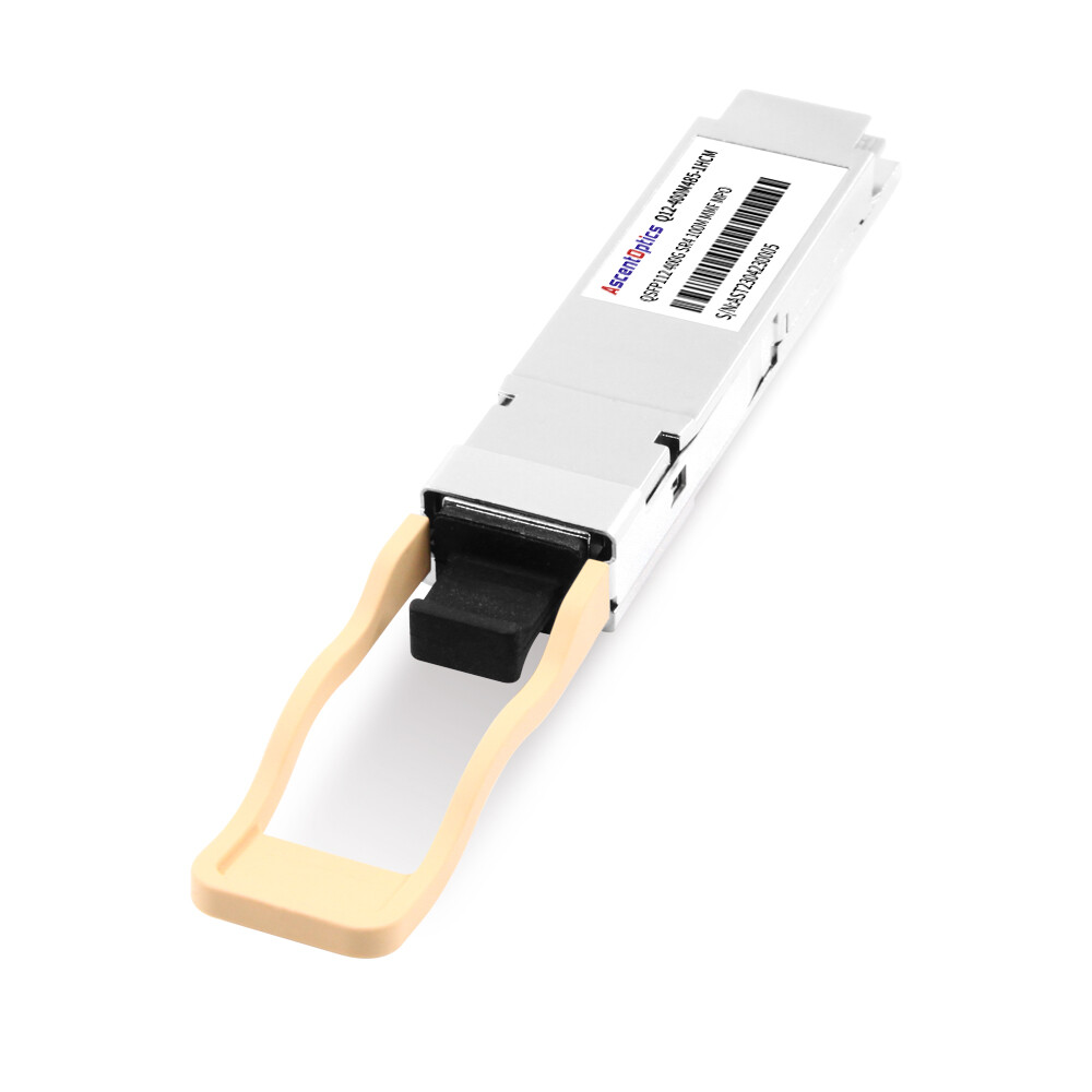
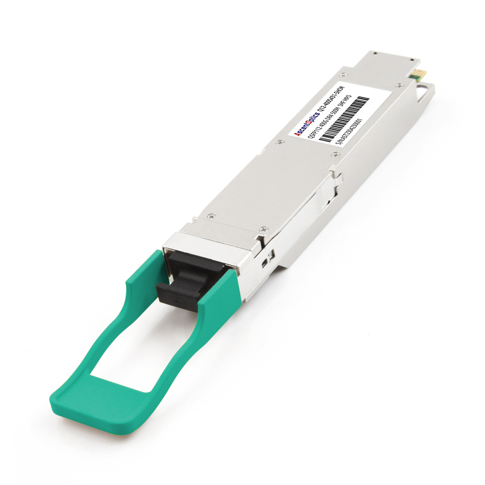
QSFP112 Form Factor Basics
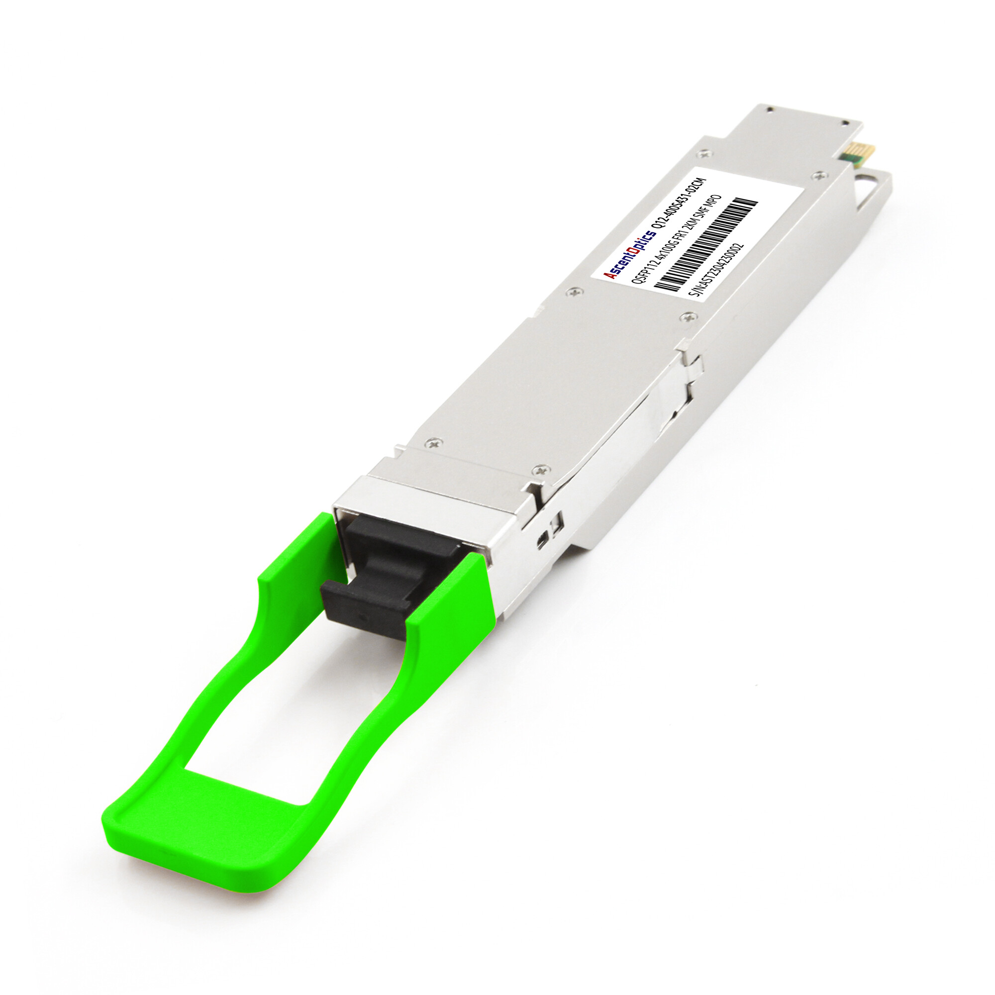
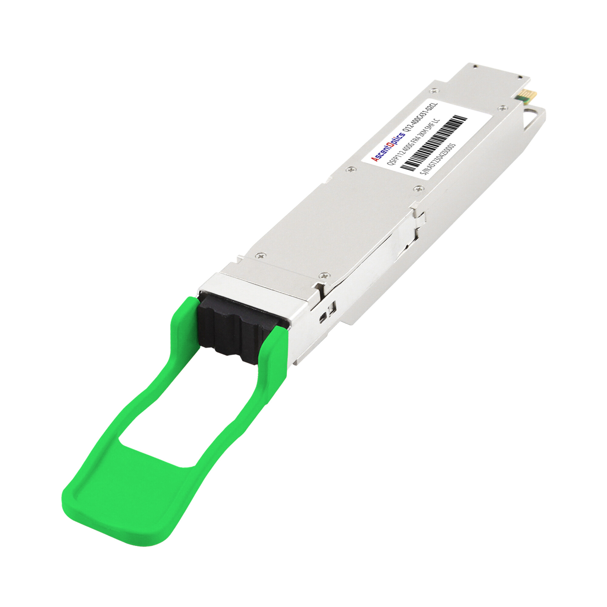
QSFP112 (Quad Small Form-Factor Pluggable 112) is a 400G optical transceiver form factor defined by the QSFP112 MSA. It uses four electrical lanes operating at 112 Gbps PAM4 signaling, delivering 400 Gbps aggregate bandwidth. The physical dimensions match earlier QSFP generations, which means QSFP112 modules fit into the same port cages as QSFP28 and QSFP56 modules on compatible switches.
This backward-compatible footprint is important for breakout deployments. A switch designed for QSFP112 can often accept QSFP28 or QSFP56 modules in the same physical slot, though the port must be configured for the correct speed and signaling mode. The QSFP112 form factor is also the native interface for NVIDIA ConnectX-7 network interface cards and Quantum-2 InfiniBand switches, making it the de facto standard for AI and HPC clusters.
Common QSFP112 Breakout Configurations
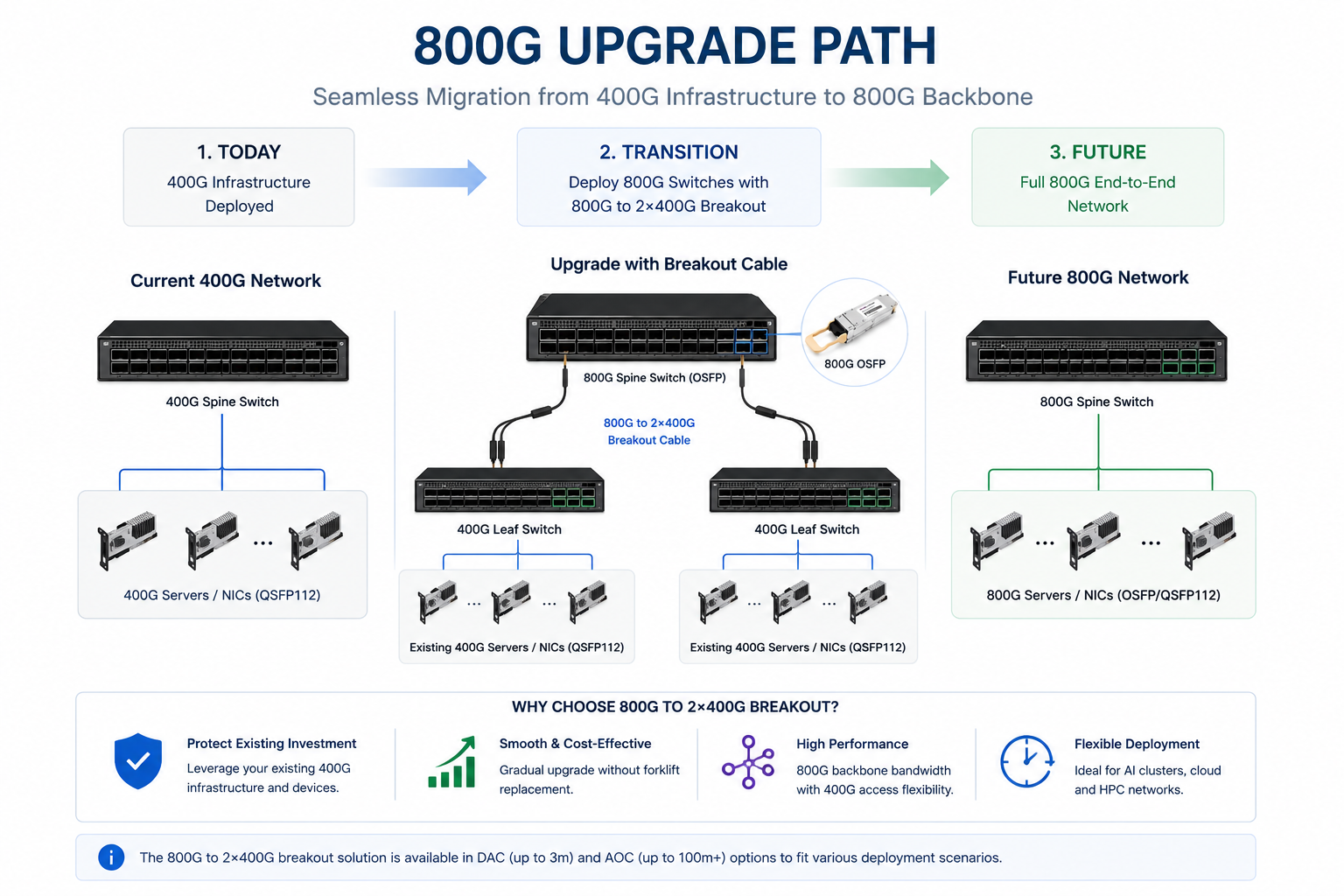
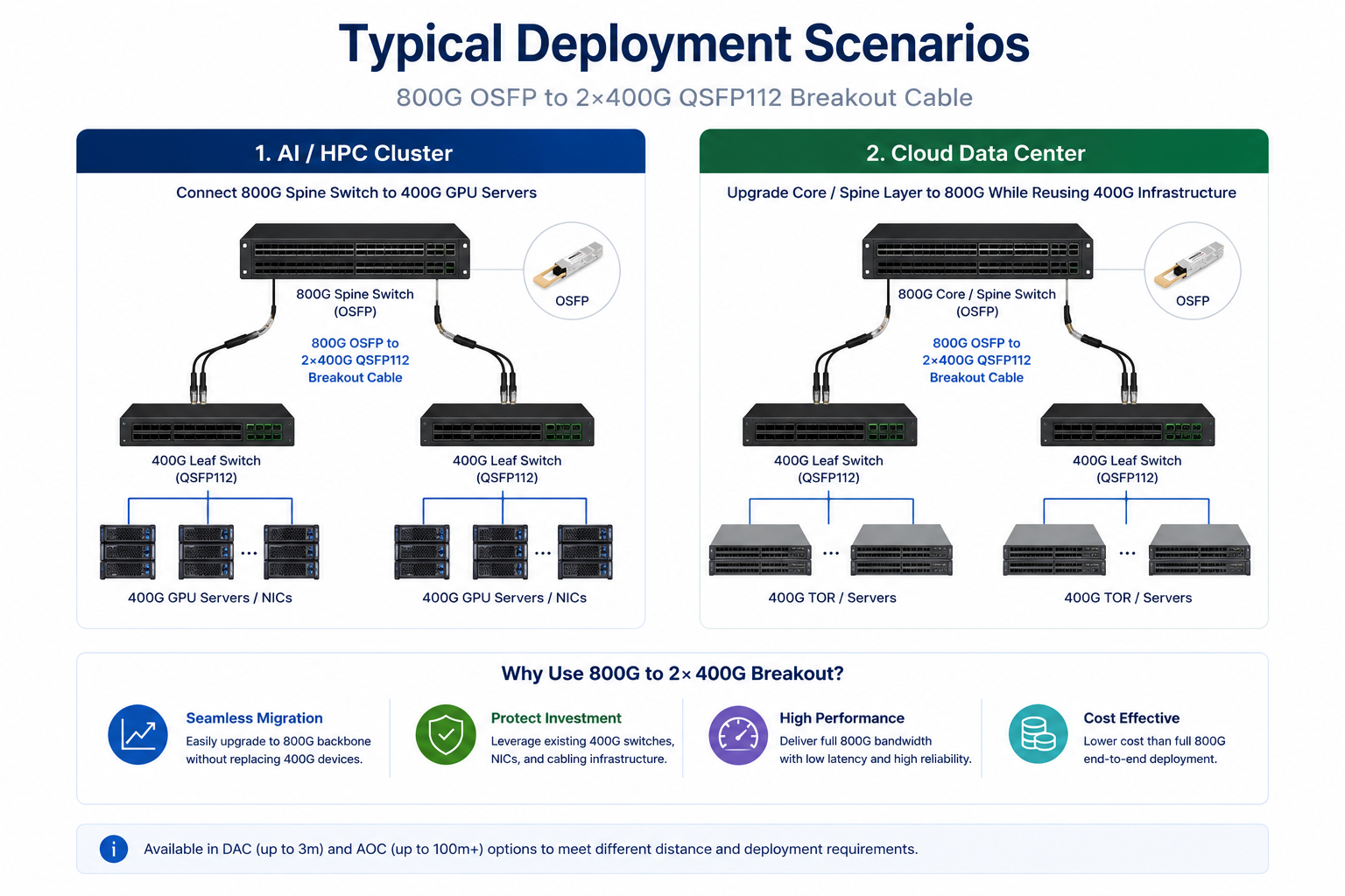
As 800G networking becomes increasingly common in AI clusters, cloud data centers, and HPC environments, breakout connectivity plays a critical role in bridging next-generation infrastructure with existing 400G deployments. Among various breakout options, 800G OSFP to 2×400G QSFP112 has emerged as one of the most widely adopted configurations.
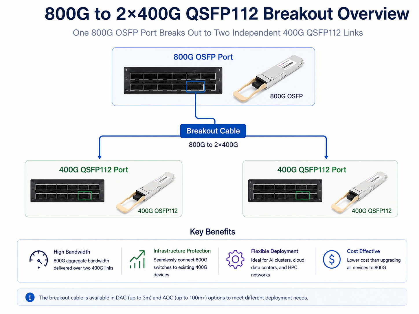
800G OSFP to 2×400G QSFP112
This is currently the most common breakout deployment for organizations migrating from 400G to 800G networks. A single 800G OSFP port is divided into two independent 400G QSFP112 links, allowing new 800G switches to connect directly to existing 400G switches, NICs, and AI servers.
Typical applications include:
- •800G spine switches connecting to 400G leaf switches
- •NVIDIA AI and HPC clusters using ConnectX-7 adapters
- •Gradual migration from 400G to 800G infrastructure
- •High-density cloud data center deployments
Because both interfaces use high-speed PAM4 signaling and 400G QSFP112 remains widely deployed across AI and data center networks, this breakout configuration provides an efficient upgrade path while protecting existing infrastructure investments.
Understanding OSFP breakout cable options helps network architects design flexible migration paths that minimize stranded capacity during speed upgrades.
Other QSFP112 Breakout Configurations
Depending on switch architecture and platform support, additional breakout configurations may also be available:
400G QSFP112 to 2×200G QSFP56
A single 400G QSFP112 port is split into two independent 200G QSFP56 connections. This configuration is commonly used in mixed-speed Ethernet networks where 200G equipment remains in production.
400G QSFP112 to 4×100G QSFP28
Some platforms support breaking a 400G port into four 100G connections through ASIC-level breakout functionality. Availability depends on the switch ASIC, firmware, and breakout implementation.
Key Takeaway
For modern AI, HPC, and cloud networking deployments, 800G OSFP to 2×400G QSFP112 breakout cables represent the most practical and widely deployed breakout architecture, enabling seamless interoperability between emerging 800G platforms and existing 400G ecosystems.
QSFP112 Breakout Cable Types: DAC, AEC, and AOC
Choosing the right cable type for a QSFP112 breakout deployment requires understanding the trade-offs between reach, power, cost, and signal integrity. Here is how the three main categories compare.
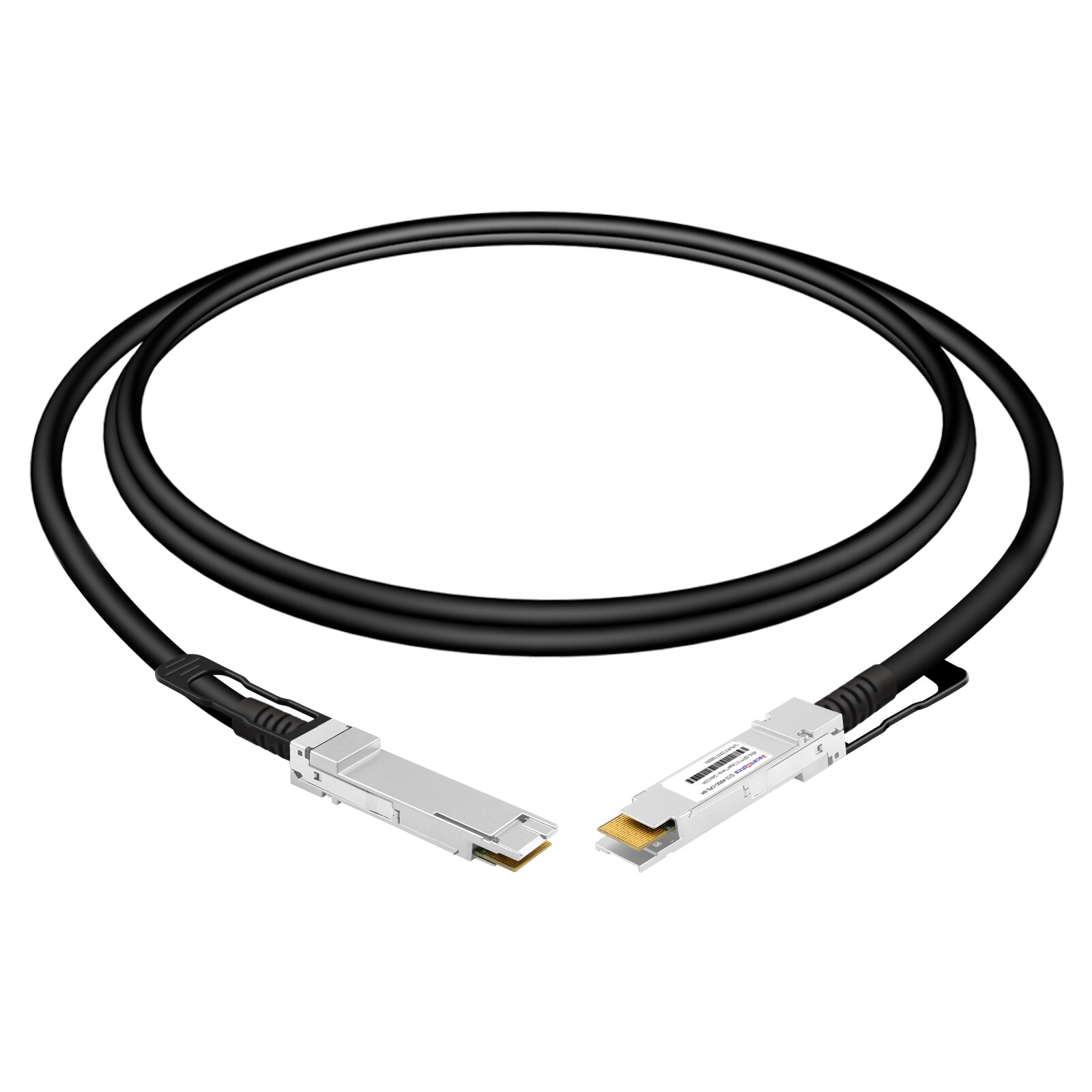
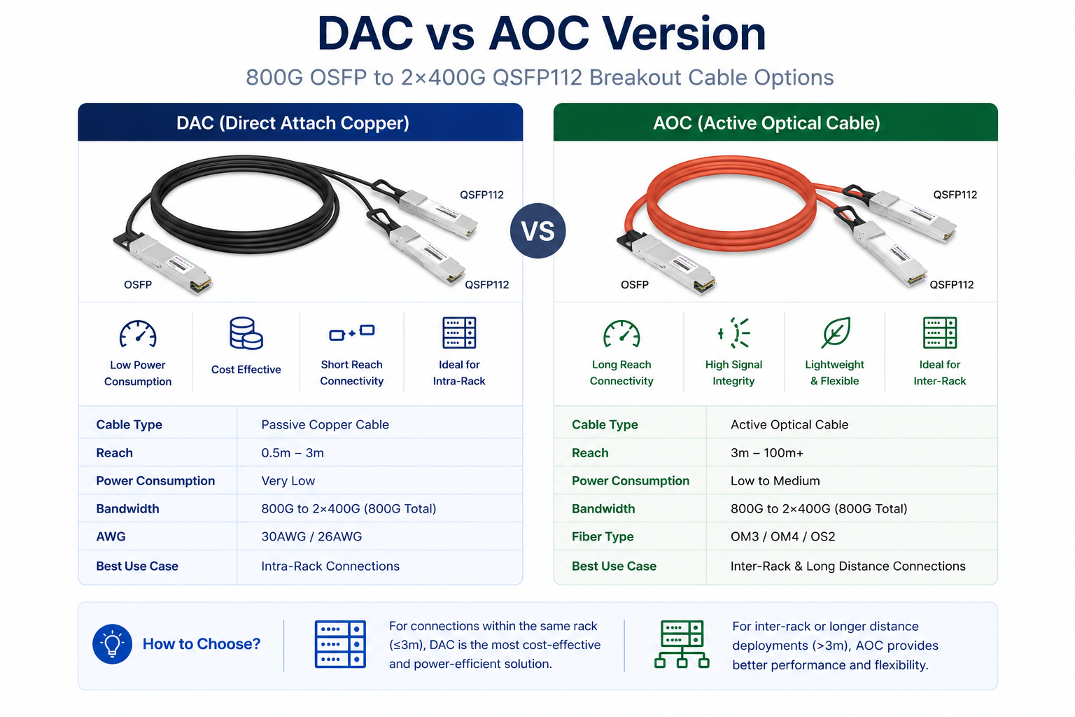
Passive Breakout DAC
Passive Direct Attach Copper (DAC) breakout cables use pure twinax copper wiring with no active electronics in the connector housing. The QSFP112 MSA and IEEE 802.3ck standards define the electrical interface, but the cable itself is a passive transmission medium.
For QSFP112 breakout configurations, passive DAC reach is typically limited to 0.5 to 2 meters. The 112G PAM4 signaling rate experiences significant attenuation in copper, and the additional trace complexity of splitting one port into four legs further reduces maximum reach. Power consumption is negligible at less than 0.1W per end, making passive breakout DAC the most energy-efficient option.
Passive breakout DAC works best for intra-rack connections where the spine switch and leaf switches sit in adjacent rack units. A 1-meter passive breakout DAC can connect a top-of-rack 400G switch to four 100G servers mounted directly below it.
Active Breakout ACC and AEC
Active Copper Cables (ACC) and Active Electrical Cables (AEC) add signal conditioning electronics inside the connector housing. These devices use redrivers or retimers to compensate for copper attenuation, extending reach beyond what passive cables can support.
For QSFP112 breakout cables, active copper options reach 2 to 5 meters. Power consumption increases to 1 to 3W per end, which is still significantly lower than optical alternatives. Active breakout cables are the practical choice when you need to cross a row or connect devices within the same rack group, but cannot keep everything within 2 meters.
The key difference between ACC and AEC is the type of signal conditioning. ACC cables use redrivers that amplify the signal but do not retime it. AEC cables use retimers that recover and regenerate the clock, providing a cleaner signal output. For QSFP112 breakout applications, AEC is generally preferred because retimers handle PAM4 signaling more reliably at 112G per lane.
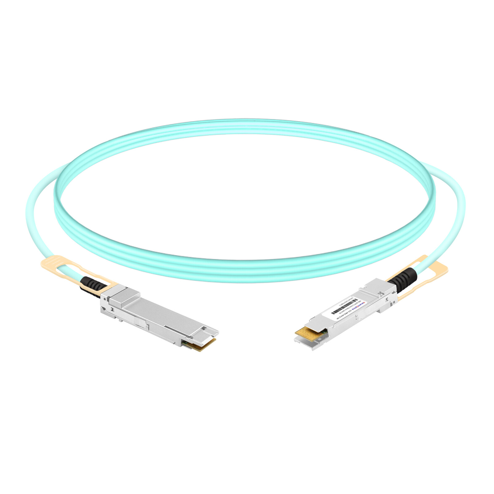
Breakout AOC
Active Optical Cable (AOC) breakout assemblies convert electrical signals to optical signals inside the connector housing and transmit them over fiber. A QSFP112 to 4x100G breakout AOC uses four independent optical channels, each with its own transmitter and receiver.
Breakout AOC reach extends from 1 meter to 30 meters, depending on fiber type and optical power budget. This makes AOC the only practical choice for inter-rack connections spanning more than 5 meters. Weight and bulk are also significantly lower than copper breakout bundles. A 4-leg copper breakout DAC is thick and stiff, while an AOC breakout uses thin fiber ribbons that route easily through cable managers.
The trade-off is power and cost. A QSFP112 breakout AOC consumes up to 10W at the host end and approximately 2.5W per breakout leg. For a 64-port deployment, that adds over 600W of heat compared to a passive DAC. Cost per link is also 5 to 10 times higher than copper.
Cable Gauge and Bundle Considerations
Breakout DAC cables use multiple coaxial pairs bundled together. Common wire gauges range from 26 AWG to 30 AWG. Thicker 26 AWG cable supports longer reach and better signal integrity, but is less flexible. Thinner 30 AWG cable bends more easily but has higher insertion loss.
When deploying breakout bundles in dense racks, cable management becomes critical. A single 4-leg breakout cable contains eight individual connectors, four on each end. In an AI cluster with hundreds of breakout links, unmanaged bundles block airflow and complicate maintenance. Use horizontal cable managers and strain relief brackets to keep breakout legs organized.
| Cable Type |
Max Reach
|
Power (QSFP112 End) |
Power (Per Leg) |
Best Use Case
|
| Passive Breakout DAC |
0.5 to 2 m
|
< 0.1W |
Near zero |
Intra-rack, adjacent devices
|
| Active Breakout AEC |
2 to 5 m
|
1 to 3W |
0.5 to 1W |
Cross-rack, row-level
|
| Breakout AOC |
1 to 30 m
|
Up to 8W |
Up to 2.5W |
Inter-rack, longer reach
|
Signaling and Why Some QSFP112 Breakouts Need Active Electronics
PAM4 vs NRZ Signaling Mismatch
The electrical interface inside a QSFP112 port uses 112G PAM4 signaling. PAM4 encodes two bits per symbol by using four distinct voltage levels, which doubles the data rate compared to traditional NRZ signaling without doubling the baud rate. This is how QSFP112 achieves 400G over only four lanes.
QSFP28 modules, by contrast, use 25G NRZ signaling. NRZ uses two voltage levels to encode one bit per symbol. A passive copper cable cannot convert PAM4 to NRZ. It simply transmits whatever electrical signal it receives. If you connect a QSFP112 PAM4 signal directly to a QSFP28 NRZ receiver through passive copper, the receiver cannot decode the four-level PAM4 waveform.
When Active Conditioning Is Required
Not every QSFP112 breakout configuration needs a retimer. The requirement depends on the signaling format on both ends:
- •QSFP112 (PAM4) to QSFP28 (NRZ): The speed adaptation and lane mapping are typically handled by the switch ASIC or NIC. The breakout cable serves as the physical interconnect and does not normally perform protocol or modulation conversion.
- •QSFP112 (PAM4) to QSFP56 (PAM4): Passive copper may work. Both sides use PAM4, though the lane rates differ. Many switch ASICs can handle the rate adaptation internally.
- •800G OSFP (PAM4) to QSFP112 (PAM4): Passive copper often works for short reach. Both ends use the same signaling format at the same or similar lane rate.
When evaluating breakout cables, always verify whether the cable includes a retimer. Product descriptions that say “passive breakout DAC” for a QSFP112 to 4x100G configuration are technically suspect unless the switch itself handles the signaling conversion internally.
QSFP56 Breakout Simplification
The 400G QSFP112 to 2x200G QSFP56 breakout is simpler from a signaling perspective. QSFP56 uses 50G PAM4 per lane. Both the source and destination use PAM4, so the breakout cable does not need to perform modulation format conversion. The switch ASIC or cable redriver handles lane rate adaptation from 112G to 50G.
Because of this simplification, passive breakout DAC cables for QSFP112 to 2x200G are more widely available and less expensive than their 4x100G counterparts. If your endpoints support 200G, this configuration reduces cabling complexity and cost.
QSFP112 Breakout vs QSFP-DD Breakout: Key Differences
Form Factor Architecture Comparison
QSFP112 and QSFP-DD are both 400G form factors, but their internal lane architectures differ significantly. QSFP112 uses four lanes at 112G PAM4. QSFP-DD supports multiple generations of lane architectures, including 8×50G PAM4 for 400G Ethernet and 8×100G PAM4 for 800G Ethernet. This architectural difference has direct implications for breakout cable design.
Because QSFP-DD has eight lanes, a 400G QSFP-DD to 4x100G breakout maps naturally. Each 100G QSFP28 leg uses two of the eight 50G lanes. No modulation conversion is required because both sides can operate in a compatible mode. This is why QSFP-DD breakout cables are more common and available in passive configurations for 4x100G.
QSFP112, with only four lanes, cannot map directly to four 100G NRZ legs without modulation conversion. The lane-to-leg mapping is one-to-one, but the signaling formats are incompatible. This makes QSFP112 breakout cables more specialized and explains why the 4x100G variant is less common than the QSFP-DD equivalent.
Want a detailed comparison with other breakout technologies? Our QSFP-DD breakout cable guide explains 400G to 100G breakout from the QSFP-DD perspective.
Breakout Cable Availability
If you search for 400G to 4x100G breakout cables today, you will find significantly more QSFP-DD options than QSFP112 options. This is not because QSFP112 is inferior. It is because the QSFP-DD architecture makes passive 4x100G breakout simpler to implement.
However, QSFP112 breakout cables are gaining traction as the form factor becomes dominant in AI and HPC environments. NVIDIA ships ConnectX-7 NICs exclusively in QSFP112. Many next-generation switches standardize on QSFP112 rather than QSFP-DD. For engineers working in these ecosystems, understanding QSFP112 breakout options is essential even if the cable selection is currently narrower.
Compatibility and Vendor Interoperability
Switch Platform Support
Not every switch with QSFP112 ports supports breakout mode. The capability depends on the switch ASIC, firmware, and port configuration options.
NVIDIA Spectrum-4: Full breakout support. 400G QSFP112 ports can break out to 4x100G or 2x200G via software configuration.
NVIDIA Quantum-2: 800G OSFP ports support 4x200G QSFP112 breakout for InfiniBand NDR. NVIDIA Quantum-2: Native 400G QSFP112 ports support NDR InfiniBand fabrics. Breakout capabilities depend on the specific switch model, firmware version, and network configuration.
Cisco Nexus 9300-GX2 series: Supports QSFP112 breakout configurations on select models. Verify the specific switch data sheet because breakout support varies by SKU.
Arista 7060X6 series: Supports 400G QSFP112 breakout to 4x100G and 2x200G on platforms with the appropriate ASIC.
Broadcom Tomahawk 5-based switches: Breakout support is implementation-dependent. Tomahawk 5 silicon supports breakout, but the final feature set depends on the switch vendor’s firmware.
NIC and DPU Compatibility
The endpoint device must also support the breakout configuration. A QSFP112 to 4x100G breakout cable does not magically create four ports on a device that only expects one.
NVIDIA ConnectX-7: Supports 400G, 200G, and 100G modes via QSFP112. Breakout to 4x100G requires the NIC to be configured in the appropriate mode.
NVIDIA BlueField-3 DPU: Uses QSFP112 ports and supports breakout configurations matching ConnectX-7.
Broadcom Thor 2: Supports QSFP112 with breakout options defined by the platform vendor.
Conclusion
QSFP112 breakout cables play a critical role in bridging mixed-speed network environments, allowing 400G and 800G platforms to interconnect with existing 100G and 200G infrastructure. Whether deployed as DAC, AEC, or AOC assemblies, breakout solutions help maximize port utilization, simplify migration paths, and reduce the cost of large-scale network upgrades.
When selecting a QSFP112 breakout cable, engineers should consider not only cable reach and media type, but also switch ASIC capabilities, breakout mode support, firmware requirements, and endpoint compatibility. Proper planning ensures reliable operation and enables a smoother transition toward next-generation AI, cloud, and high-performance computing networks.
Frequently Asked Questions
What is a QSFP112 breakout cable?
A QSFP112 breakout cable is a high-speed interconnect assembly that splits one QSFP112 400G port into multiple lower-speed ports, such as four 100G QSFP28 or two 200G QSFP56 connections. It enables flexible port fan-out in mixed-speed data centers, allowing 400G spine switches to connect directly to 100G or 200G leaf switches and servers.
What breakout configurations does QSFP112 support?
QSFP112 breakout cables support four common configurations: 400G QSFP112 to 4x100G QSFP28, 400G QSFP112 to 2x200G QSFP56, 800G OSFP to 2x400G QSFP112, and 800G OSFP to 4x200G QSFP112.
Can QSFP112 break out to 4x100G QSFP28?
Yes, but this configuration typically requires active electronics in the cable assembly. QSFP112 uses 112G PAM4 signaling while QSFP28 expects 25G NRZ. The breakout cable must perform modulation conversion, which is done by retimers or gearboxes built into active AEC or AOC breakout cables.
What is the maximum length of a QSFP112 breakout DAC?
Passive QSFP112 breakout DAC cables typically reach 0.5 to 2 meters. Active AEC breakout cables extend this to 2 to 5 meters. For longer reaches, breakout AOC cables support distances up to 30 meters.
What is the difference between the QSFP112 breakout DAC and AOC?
Breakout DAC uses copper wiring with no optical conversion. It offers the lowest power and cost but limited reach. Breakout AOC uses integrated optical transceivers and fiber, supporting much longer distances with lower bulk but higher power consumption and cost.
Post Views: 848