Today’s world is focused on data processing and its transmission across vast networks. In this regard, it would also be significant to mention that fiber optic cable technology has become essential for all communication systems. Out of the numerous fiber optic solutions available in the market, the MPO breakout cables help enhance interconnectivity within the networks. The purpose of this article is to introduce the readers to the concept of remaining relevant in the global trend towards the deployment of MPO breakout cables by being cognitively equipped on the structure as well as the role of the cable in enhancing network capabilities. There is no shortage of willingness for architects, developers, contractors, and other information technology personnel to have such knowledge, allowing them to make the best decision to take them towards the best decision.
What is an MPO Breakout Cable?
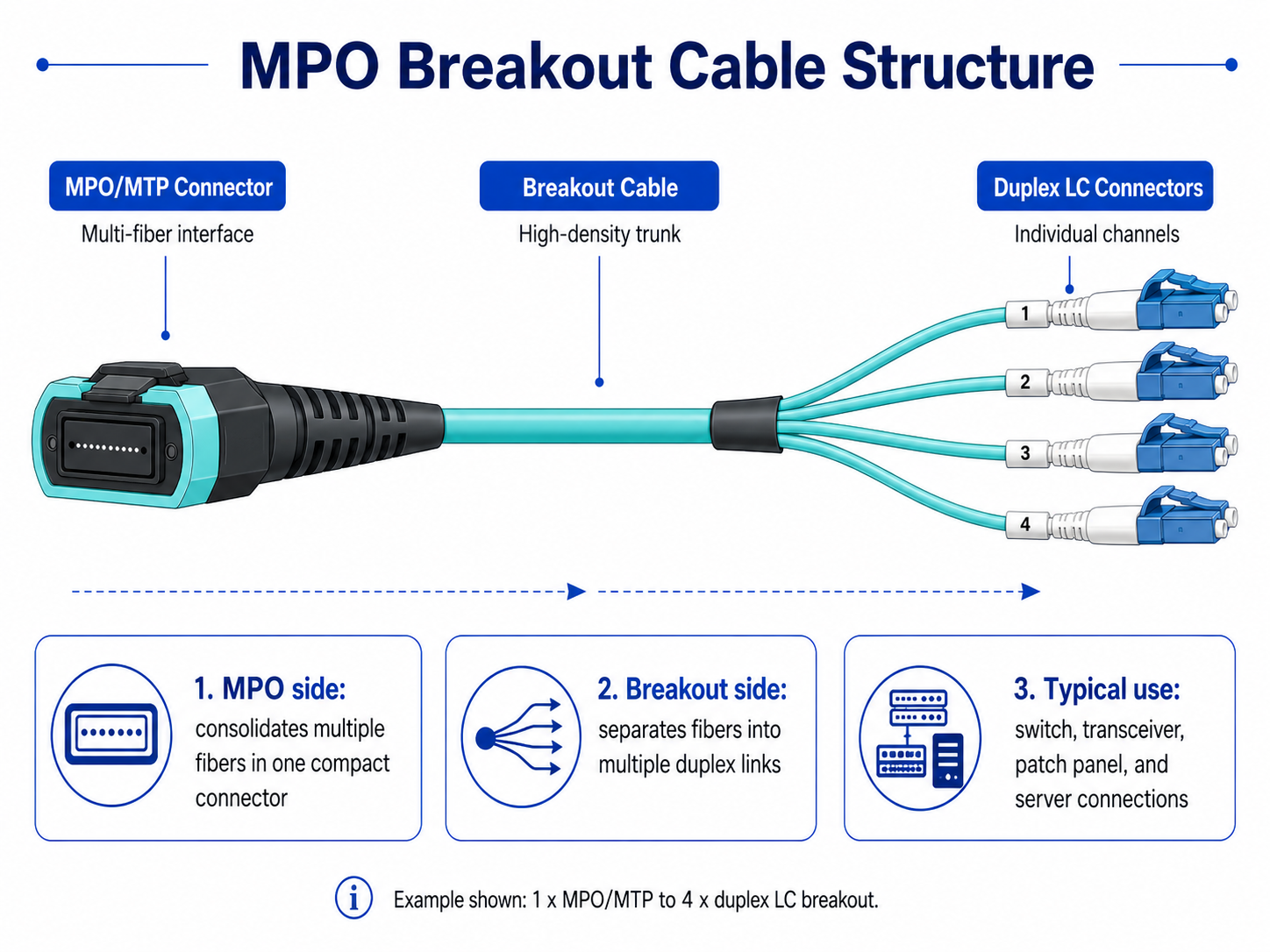
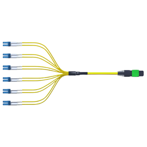
An MPO breakout cable, also called an MPO fanout cable, is a fiber optic cable assembly that converts a high-density MPO or MTP connector into multiple individual duplex connectors such as LC. MPO breakout cables simplify structured cabling, reduce deployment complexity, and support flexible migration paths between different Ethernet generations.
The MPO side aggregates multiple optical fibers into a single compact interface, while the breakout side separates those fibers into individual channels for connection to transceivers, switches, patch panels, or servers.
In modern Ethernet deployments, MPO breakout cables are commonly used to connect:
- •40G transceivers to 10G interfaces
- •100G transceivers to 25G interfaces
- •400G transceivers to multiple lower-speed optical links
- •High-density switch ports to structured cabling systems
Today, MPO breakout assemblies are widely deployed in spine-leaf architectures, AI clusters, enterprise core networks, and hyperscale data centers where high-density optical interconnects are essential. Whether supporting 40G, 100G, 400G, or next-generation 800G networks, MPO breakout cabling has become a critical part of modern fiber infrastructure design. Unlike traditional duplex patch cables, MPO breakout assemblies significantly reduce cable bulk and improve rack-level cable management in dense networking environments.
How MPO Breakout Cables Work
MPO breakout cables use parallel optical transmission, where multiple optical lanes operate simultaneously across separate fibers.
For example:
- •A 40GBASE-SR4 transceiver uses four transmit fibers and four receive fibers
- •A 100GBASE-SR4 transceiver also uses 8 active fibers
- •A 400G SR8 transceiver uses 16 fibers
The MPO connector consolidates these fibers into a single high-density interface, while the breakout side separates the lanes into individual duplex connections. This allows one high-speed uplink to connect directly to multiple lower-speed devices without requiring additional patching complexity.
For example:
In many data center deployments, breakout cabling provides a practical migration strategy by allowing existing lower-speed infrastructure to coexist with newer high-speed switching platforms.
Features:
- •High Fiber Count:MPO cables can accommodate any number of fibers. The most common are 8, 12, or 24 fibers in a single connector, which can greatly enhance the number of data channels in a network.
- •Compact Design:The MTP/MPO network connectors’ compact nature saves space, allowing dense cabling infrastructure configuration without bulky network layouts.
- •Quick Deployment:Firestorm all Firestorm all They liked installation significantly easier, allowing larger structures to be completed more efficiently and helped encourage further connection in future networks.
- •Versatility:In addition to the two standard interchangeable connectors LC or SC, MPO connectors are effective in network expansion as they can work alongside the pre-existing connectors.
- •Enhanced Performance:The use of MPO breakout cables reduces the risk of losing signal strength and achieving maximum use of low multimode or single mode fibers with the troublesome side of always having substantial amounts of data transmission capacities.
Such dense packing of features implies that MPO cables are critical elements of modern, high–network infrastructures.
MPO vs MTP Connectors
Although the terms MPO and MTP are often used interchangeably, they are not technically identical.
- •MPO (Multi-Fiber Push-On) is the IEC-standardized connector format used for high-density fiber optic connectivity.
- •MTP is a branded MPO connector developed by US Conec that includes several mechanical and optical enhancements.
Key Differences Between MPO and MTP
| Feature |
MPO
|
MTP
|
| Definition |
Standard connector type
|
Enhanced MPO connector
|
| Ferrule Quality |
Standard
|
Higher precision options
|
| Insertion Loss |
Standard
|
Lower-loss options available
|
| Mechanical Design |
Basic
|
Improved alignment and durability
|
| Performance |
General applications
|
High-performance data center deployments
|
Most modern hyperscale and AI data center deployments prefer MTP connectors because of their lower insertion loss and improved mechanical reliability.
Common MPO Fiber Counts
MPO connectors are available in several standardized fiber counts, each designed for specific Ethernet architectures, transmission methods, and cabling requirements. As networks continue evolving from 40G and 100G to 400G and 800G, selecting the correct MPO fiber count has become increasingly important for both performance and scalability.
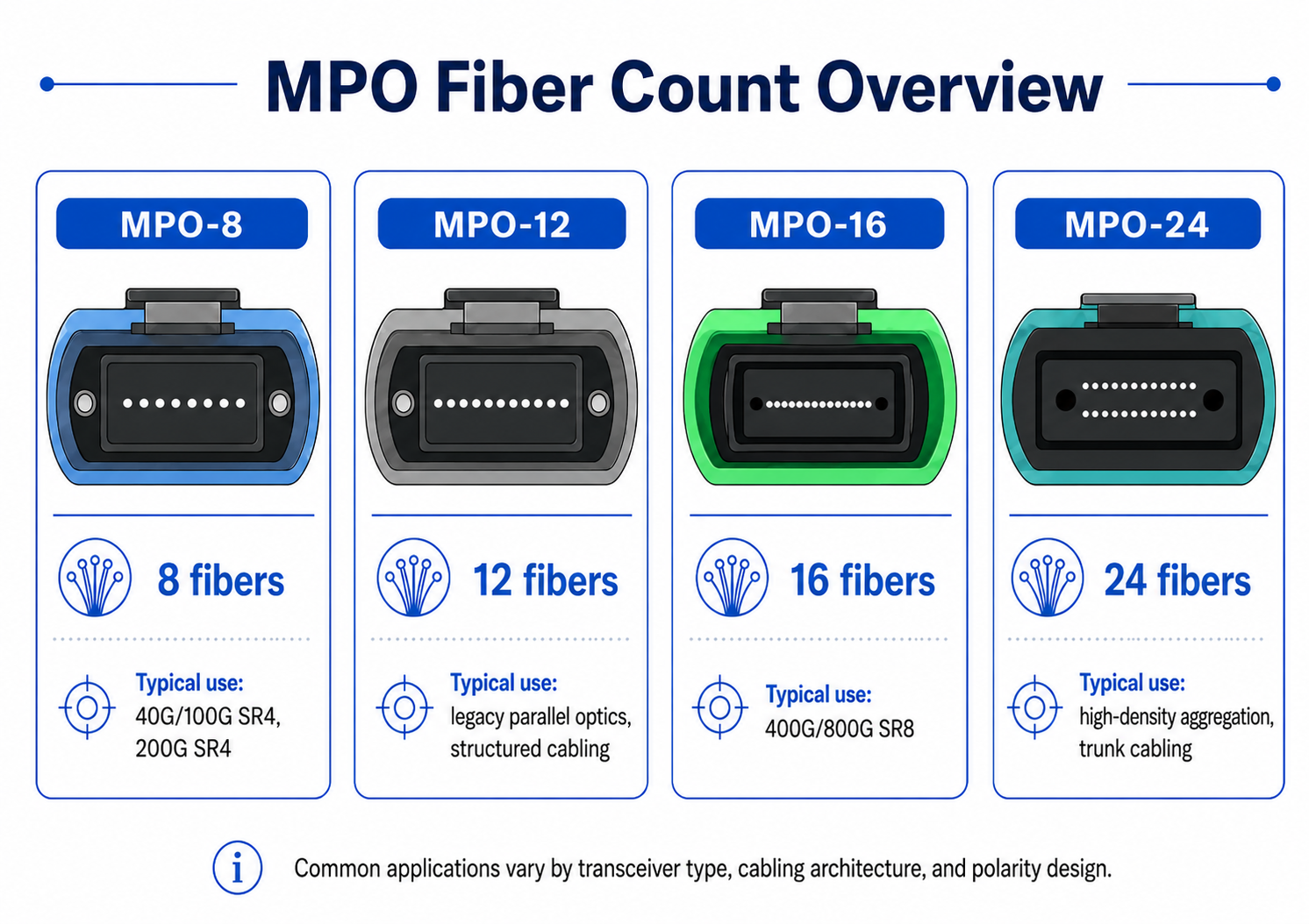
MPO-8
MPO-8 uses 8 optical fibers, typically organized as:
- •4 transmit fibers (TX)
- •4 receive fibers (RX)
This configuration is widely used in parallel optics applications and offers very efficient fiber utilization because all fibers are active.
Typical applications include:
- •40GBASE-SR4
- •100GBASE-SR4
- •HDR InfiniBand
Compared with MPO-12, MPO-8 eliminates unused fibers, making it a more efficient option for modern data center environments focused on optimizing fiber density and cabling efficiency.
MPO-12
MPO-12 has historically been the most widely deployed MPO format in structured cabling systems. Although many 40G and 100G SR4 applications only utilize 8 active fibers, MPO-12 became the industry standard during the early growth of parallel optics networks and remains extremely common in existing infrastructure.
Typical applications include:
- •Structured cabling systems
- •Legacy 40G/100G deployments
- •Patch panel interconnects
- •Spine-leaf migration environments
Its primary advantages include broad ecosystem compatibility, mature deployment practices, and extensive market availability. However, because some fibers may remain unused in certain applications, fiber utilization efficiency is lower than MPO-8.
MPO-16
As 400G and 800G Ethernet deployments continue accelerating, MPO-16 is becoming increasingly important in next-generation high-density optical networks. MPO-16 is commonly used for:
- •400G SR8
- •800G SR8
- •AI and GPU fabrics
- •Hyperscale cloud infrastructure
This architecture supports:
- •8 transmit lanes
- •8 receive lanes
Compared with MPO-12, MPO-16 is better aligned with modern 8-lane PAM4 networking architectures, making it especially suitable for high-performance AI clusters and large-scale data center fabrics.
MPO-24
MPO-24 provides even higher fiber density and is commonly deployed in:
- •Backbone cabling
- •High-density aggregation
- •Large-scale patching environments
- •Hyperscale structured cabling systems
Because MPO-24 supports a larger number of optical lanes within a compact footprint, it is highly effective in environments where maximizing cabling density is critical.
However, the increased fiber count also introduces greater complexity in terms of polarity management, cable routing, and installation planning.
Benefits of MPO Breakout Cables
MPO breakout cables not only improve cabling density, but also enhance deployment efficiency, scalability, and operational flexibility. These advantages have made MPO infrastructure a key component of modern high-speed data center networks.
High-Density Connectivity
Compared with traditional duplex fiber cabling, MPO breakout solutions enable significantly higher connection density within the same physical space. For example, a single MPO trunk can replace multiple LC duplex patch cables, reducing congestion inside racks, cable trays, and patch panels.
This becomes increasingly important in:
- •Spine-leaf architectures
- •AI clusters
- •GPU fabrics
- •Hyperscale cloud environments
As switch port density continues increasing in 400G and 800G deployments, high-density MPO infrastructure has become essential for efficient data center design.
Simplified Cable Management
Traditional duplex cabling can quickly create cable congestion in large-scale environments, making maintenance and airflow management more difficult. MPO breakout cabling significantly reduces cable volume, resulting in cleaner rack layouts and more organized cable pathways.
Improved cable organization also helps optimize airflow and cooling efficiency, which is particularly important in high-density AI and HPC environments.
Faster Deployment
Most MPO breakout assemblies are factory-terminated and pre-tested before shipment. Compared with field termination or on-site splicing, pre-terminated MPO systems offer:
- •Faster installation
- •Lower labor costs
- •More consistent performance
- •Reduced deployment risk
For hyperscale and enterprise data centers, this can significantly shorten deployment timelines.
Flexible Migration Paths
One of the biggest advantages of MPO breakout architecture is its ability to support gradual network upgrades. For example:
- •A 400G switch port can connect to multiple 100G servers
- •High-speed spine switches can support lower-speed leaf infrastructure
This allows organizations to modernize their networks without replacing all equipment simultaneously. As a result, MPO breakout cabling helps reduce migration costs while protecting existing infrastructure investments.
Better Scalability
MPO infrastructure is highly scalable and supports multiple Ethernet generations within the same structured cabling environment. A properly designed MPO system can support 10G to 800G, and future technologies such as:
- •6T Ethernet
- •AI optical fabrics
- •Next-generation parallel optics
Because of this long-term scalability, many modern data centers now build their optical infrastructure around MPO and MTP connectivity standards.
MPO Breakout Cable Selection Considerations
Selecting the right MPO breakout cable involves more than simply matching connector types. Modern high-speed optical networks require careful consideration of fiber architecture, loss budgets, compatibility, and future scalability.
Fiber Type
The first step is selecting the appropriate fiber type based on transmission distance and deployment requirements.
Multimode Fiber
Multimode fiber is commonly used for short-range data center interconnects, including:
- •Rack-to-rack connections
- •Spine-leaf architectures
- •Intra-data-center links
Common multimode fiber types include:
These solutions typically offer lower deployment costs and simpler installation.
Singlemode Fiber
Singlemode fiber is better suited for:
- •Long-distance transmission
- •Data center interconnects (DCI)
- •Campus networks
- •Metro and backbone infrastructure
OS2 is the most common singlemode fiber type used in modern high-speed deployments. Although singlemode solutions generally cost more initially, they provide superior distance capability and long-term scalability.
Connector Compatibility
It is essential to verify full compatibility between the breakout cable and the connected devices. Important considerations include:
- •MPO vs MTP interfaces
- •Male vs female connectors
- •Key-up/key-down orientation
- •LC duplex connector compatibility
Incorrect connector configurations can prevent successful link establishment.
Polarity Management
Polarity is one of the most critical aspects of MPO deployment. Type A, Type B, and Type C polarity methods determine how transmit and receive fibers align between devices. Incorrect polarity can lead to:
- •Link failures
- •Unstable connections
- •Difficult troubleshooting
For this reason, polarity validation should always be performed before deployment.
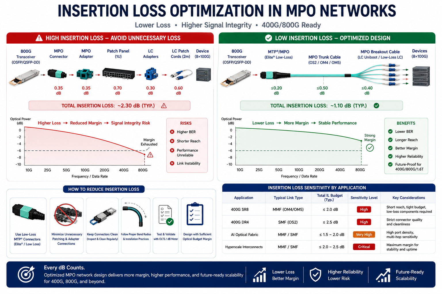
Insertion Loss Budget
As 400G and 800G optical networks continue to scale, insertion loss tolerance is becoming increasingly critical. High-speed transmission standards such as 400G SR8 and 400G DR4 operate with tighter optical budgets, making the overall cabling design more sensitive to connector and link loss. To maintain stable signal integrity and reliable network performance, data center operators are encouraged to use low-loss MTP/MPO connectors, minimize unnecessary patch panels and adapters, and reduce the total number of connection points throughout the link.
These practices are particularly important in AI optical fabrics, hyperscale interconnects, and other high-density environments where even small amounts of additional loss can affect link stability, reach, and overall system efficiency.
Cable Length Planning
Cable lengths should be carefully planned to balance routing flexibility and cable organization. Overly long cables can:
- •Increase cable clutter
- •Restrict airflow
- •Complicate maintenance
Cables that are too short may reduce routing flexibility and create installation challenges. Proper cable planning improves both operational efficiency and rack-level organization.
Future Scalability
Modern data centers must also consider future network upgrades during infrastructure planning. Examples include:
- •100G to 400G migration
- •400G to 800G migration
- •Future AI fabric expansion
Choosing scalable MPO infrastructure today can significantly reduce future recabling costs and simplify long-term network evolution.
Installation and Maintenance Tips for MPO Cables
Proper installation and maintenance are essential for ensuring reliable MPO/MTP® cable performance, especially in modern 40G, 100G, 400G, and 800G high-density networks. Because MPO connectors contain multiple fibers in a single interface, even minor contamination or handling mistakes can significantly affect insertion loss and overall link stability.
Handle MPO Connectors Carefully
MPO connectors are precision optical components and should always be handled with care. Avoid touching the end face directly, as oils and dust from fingers can contaminate the fiber surface and increase signal loss. During installation, keep dust caps in place until the connector is ready to be plugged in. Excessive pulling, twisting, or bending should also be avoided, since fiber stress can damage the internal structure and reduce transmission reliability.
Observe Proper Bend Radius
Maintaining the correct bend radius is critical for MPO trunk and breakout cables. Tight bends may introduce macro-bending loss, particularly in high-speed multimode and single-mode applications. As a general guideline, the bend radius should not be smaller than ten times the cable diameter during operation and even larger during installation. Proper cable routing and management trays can help minimize stress on the fiber.
Keep Connectors Clean
Connector cleanliness has a direct impact on insertion loss and return loss. Before every connection, MPO end faces should be inspected and cleaned using dedicated MPO cleaning tools or lint-free wipes designed for fiber optics. Even microscopic dust particles can degrade signal quality in 400G and 800G links. Following the “inspect before you connect” practice helps prevent avoidable network issues and reduces troubleshooting time.
Verify Polarity and Fiber Mapping
MPO systems rely on correct polarity alignment to ensure transmit and receive channels match properly. Before deployment, confirm that the MPO polarity type (Type A, Type B, or Type C) matches the network design and transceiver requirements. Incorrect polarity is one of the most common causes of link failures in parallel optical systems.
Minimize Insertion Loss
As network speeds continue increasing, insertion loss budgets become more stringent. To maintain optimal signal integrity, reduce unnecessary patching points and use low-loss MPO connectors whenever possible. High-quality cabling components are especially important in applications such as 400G SR8, 400G DR4, AI clusters, and hyperscale data center fabrics where optical margins are tighter.
Perform Regular Inspection and Testing
Routine maintenance can help identify potential problems before they affect network performance. Periodically inspect cable routing, connector condition, and port cleanliness. Optical testing tools such as insertion loss testers and OTDR equipment can be used to verify link health and detect hidden faults. Keeping accurate cable labeling and documentation also simplifies future upgrades and troubleshooting.
Store and Manage Cables Properly
Unused MPO cables should be stored in clean, dry environments with protective caps installed. Proper cable management not only improves airflow and rack organization but also reduces the risk of accidental fiber damage during maintenance activities. In large-scale data centers, structured cable management becomes increasingly important for operational efficiency and scalability.
Future of MPO Breakout Connectivity
As Ethernet speeds continue increasing toward 800G and 1.6T architectures, MPO connectivity will remain essential for parallel optical transmission. Emerging technologies such as:
- •224G SerDes
- •AI-optimized optical fabrics
- •Co-packaged optics
- •Ultra-high-density switch architectures
will further increase demand for scalable MPO-based infrastructure.
Modern data center operators are increasingly designing structured cabling systems around MPO and MTP connectivity to support long-term bandwidth growth and simplified migration planning.
Conclusion
MPO breakout cables have become a foundational technology in modern high-speed networking environments. By enabling efficient fan-out connectivity between high-density optical interfaces and multiple lower-speed links, MPO breakout assemblies simplify structured cabling, improve scalability, and support flexible migration paths across multiple Ethernet generations.
Whether deployed in enterprise networks, hyperscale cloud environments, AI clusters, or high-performance computing infrastructures, MPO breakout technology provides the density, flexibility, and operational efficiency required for modern optical networking.
As 400G and 800G deployments continue accelerating, properly designed MPO infrastructure will remain critical for supporting future data center growth.
Reference Sources
Optical fiber
Fanout cable
Small Form-factor Pluggable
Frequently Asked Questions (FAQs)
Q: What are MPO breakout cables, how do they work, and where are they used?
A: An mpo breakout cable, or a mpo fanout as commonly known, is a multi-fiber optic cable assembly that is configured to terminate multiple individual connectors, such as duplex lc or sc on one end and a multi-fiber mpo/mpot connector on the other end. This cable makes it possible to interconnect high-density MPs with single fibers for patching purposes with different network devices with differing connectors and types.
Q: How many types of MPO breakout cables exist?
A: The standard mpo breakout cable type is eight fiber qsfp to 4x duplex lc, 12 fiber mpo to 6x duplex lc, and 24 fiber mpo to 12x duplex lc. Such wires can be configured in many types of fibers, including om3/om4/om5 for multimode applications and os2 for single mode. Setting up standard and custom cables will require strict compatibility and configuration.
Q: What are Type A and Type B types of MPO breakout, and what is their difference?
A: Type A and Type B are two different locking designs utilized in MPO breakout waveguides. Type B, which is more popular, retains the straight-through mapping of fibers in the assembly that goes from the MPO end to the individual connectors. A type A cable, on the other hand, has a reversed polarity, which is needed for some network configurations. It is important to get the right type for your network topology design.
Q: Why should I use MPO breakout cables in my fiber optic network?
A: MPO breakout cables offer several benefits, such as space-efficient connectivity, better cable management, and convenient transition across varying network capacities (that is, 10G, 40G, and 100G). They further allow the use of high-capacity device interfaces, such as the QSFP transceiver, to be connected to several lower-capacity devices through SFP+ connectors.
Q: Which MPO breakout cable would be appropriate for my network?
A: When choosing an MPO breakout cable, consider the fiber type (multimode or single mode), connector type (MTP to LC and SC or other), fiber count (e.g., 8, 12, or 24 strands), cable length, and polarity (Type A or Type B). Also, make sure the cable is compatible with your networking devices and the required bandwidth.
Q: What is the importance of aqua color in MPO breakout cables?
A: When the jacket of a cable is aqua, it is easily recognized as a multimode fiber optic cable, usually rated OM3 or OM4. This system assists in the rapid location of the cable type in complicated network field installations. Single-mode cables are often yellow, e.g., OS2, while OM5 multi-mode takes on lime green; switchboard patch cable is commonly used for connecting multifunctional devices in the network instead.
Q: How do MPO breakout cables facilitate high-density fiber optic installations?
A: MPO breakout cables facilitate high-density installations by terminating multiple individual fibers with a single MPO connector. This lessens the amount of connector and cabling required and, therefore, takes up less room in patch panels or cable trays. This is especially useful in data centers and other places where high density is an issue.
Q: Are the MPO breakout cables designed with other types of connectors in mind?
A: The MPO breakout cables offer a wide range of connector types. These include the more familiar duplex LC connectors, as well as options with ST, SC, or FC connectors. The MPO end typically has MTP connectors, which are an upgraded version of MPO designed by US Conec.
Q: What basic practices should users adopt when working with an MPO breakout cable?
A: When working with MPO breakout cables, it is necessary to avoid applying excessive force that would result in bending them below their minimum bend radius to prevent signal loss. Avoid working with or using connectors if dirty, or do not forget to wear dust caps when not in use. When a certain installation requires certain fire ratings to be met, use the right cables with jackets with the right ratings, such as LSZH or OFNP. Check and clean the connectors from time to time to guarantee peak efficiency.
Post Views: 7,340


