If you are planning a 400G data center deployment, you have probably faced similar decisions. The shift from 100G to 400G at the access layer is no longer limited to hyperscale backbones. AI clusters, high-density computing, and cloud expansion are pushing 400G connectivity to the Top-of-Rack switch. QSFP112 has emerged as the form factor of choice for this transition. But deploying it successfully requires more than understanding datasheets. You need a practical grasp of thermal budgets, cabling infrastructure, and switch compatibility.
Need help selecting the right module for your network? Explore Ascent Optics’ QSFP112 transceiver portfolio or contact our engineers for a free compatibility review.
What Is QSFP112? Technical Overview for Network Engineers
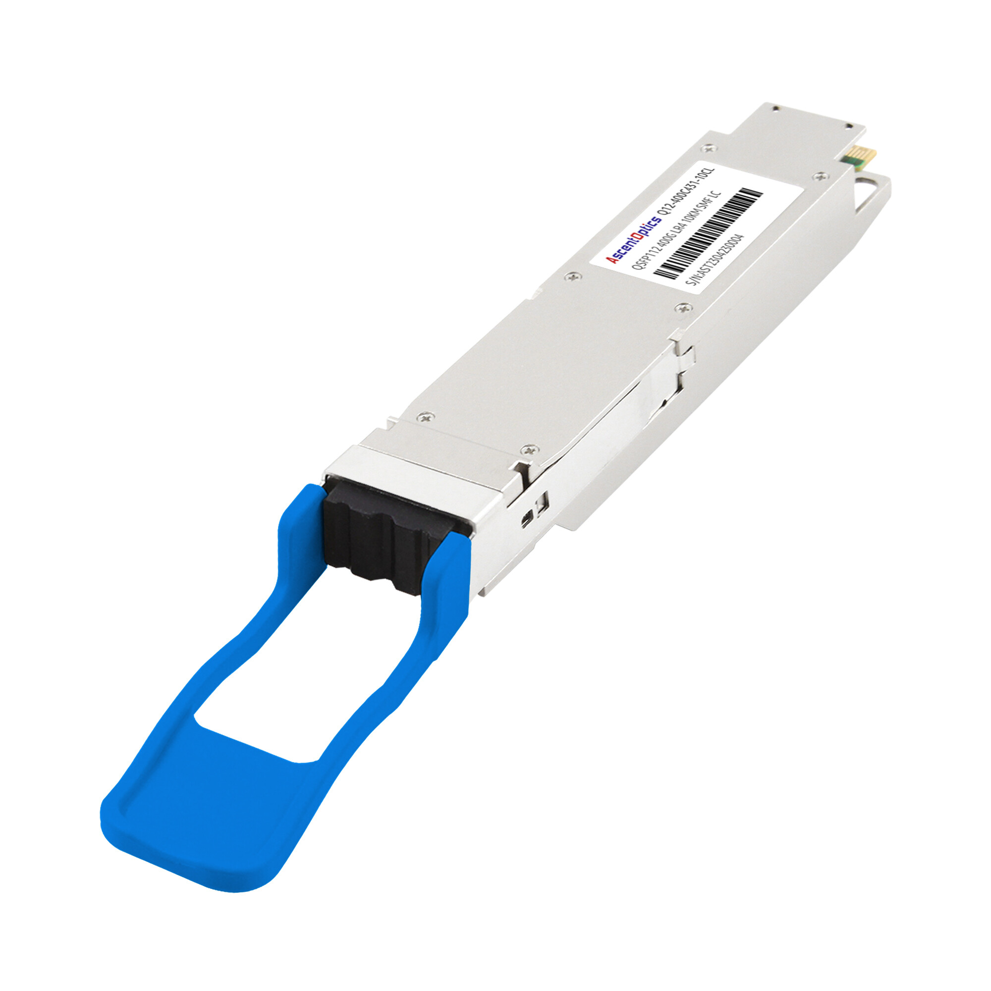
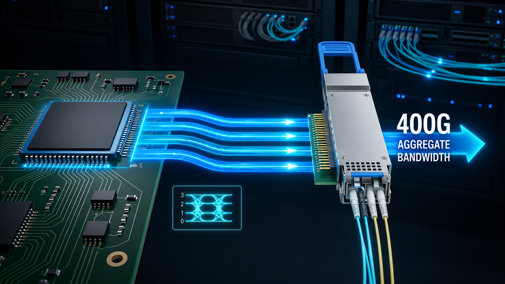
QSFP112 (Quad Small Form-Factor Pluggable 112) is a 400G optical transceiver module that uses four electrical lanes operating at 112 Gbps each. It relies on PAM4 (Pulse Amplitude Modulation 4-level) signaling to achieve this per-lane data rate, which doubles the bits per symbol compared to traditional NRZ modulation. The aggregate bandwidth reaches 400 Gbps while maintaining the same physical footprint as QSFP28 modules.
4x112G PAM4 Architecture
The core innovation behind QSFP112 is its lane architecture. While early 400G QSFP-DD implementations commonly used 8×50G PAM4 electrical lanes, QSFP112 adopts a native 4×112G electrical architecture aligned with the latest generation of 112G SerDes switch ASICs and NICs. This simplifies signal routing on host boards and reduces the overall electrical complexity. The trade-off is more demanding signal integrity requirements, which modern switch ASICs handle through integrated DSP and forward error correction.
Form Factor and Physical Dimensions
QSFP112 maintains the 18.4mm module width established by the QSFP family. It fits into standard QSFP cages and uses the same MSA-defined mechanical envelope. Network equipment manufacturers can support QSFP112 without redesigning front panels or cage assemblies. This mechanical compatibility is a major advantage for data centers upgrading from 100G or 200G infrastructure.
Backward Compatibility with QSFP28/QSFP56 Cages
QSFP112 modules are physically compatible with QSFP28 and QSFP56 cages. However, electrical compatibility depends on the host equipment. A switch must support 112G PAM4 SerDes to operate QSFP112 modules at full speed. Some platforms can negotiate down to support legacy modules, but this varies by vendor and ASIC generation. Always verify host compatibility before deployment.
QSFP112 Module Types and Distance Ratings
Selecting the correct QSFP112 variant is the first decision in any deployment. Each type is optimized for specific distances, fiber types, and network topologies. The table below summarizes the key specifications.
| Module Type |
Fiber Type
|
Distance |
Connector |
Wavelength |
Typical Power
|
| 400G-SR4 |
MMF (OM4/OM5)
|
50-100m |
MPO-12 APC |
850nm |
8-9W
|
| 400G-DR4 |
SMF (OS2)
|
500m |
MPO-12 APC |
1310nm |
9-10W
|
| 400G-DR4+ |
SMF (OS2)
|
2km |
MPO-12 APC |
1310nm |
9-10W
|
| 400G-FR4 |
SMF (OS2)
|
2km |
Duplex LC |
1310nm (CWDM) |
9-10W
|
| 400G-LR4 |
SMF (OS2)
|
10km |
Duplex LC |
1310nm (LAN-WDM) |
10-12W
|
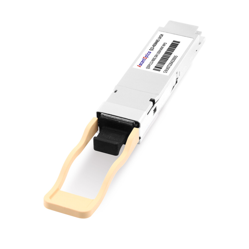
SR4: Multimode for Top-of-Rack
The SR4 variant uses VCSEL lasers at 850nm to transmit over multimode fiber. It supports distances up to 50 meters on OM4 and 100 meters on OM5. SR4 is the standard choice for intra-rack and adjacent-rack connectivity in data centers. Its lower power consumption and lower cost make it ideal for high-density ToR deployments.
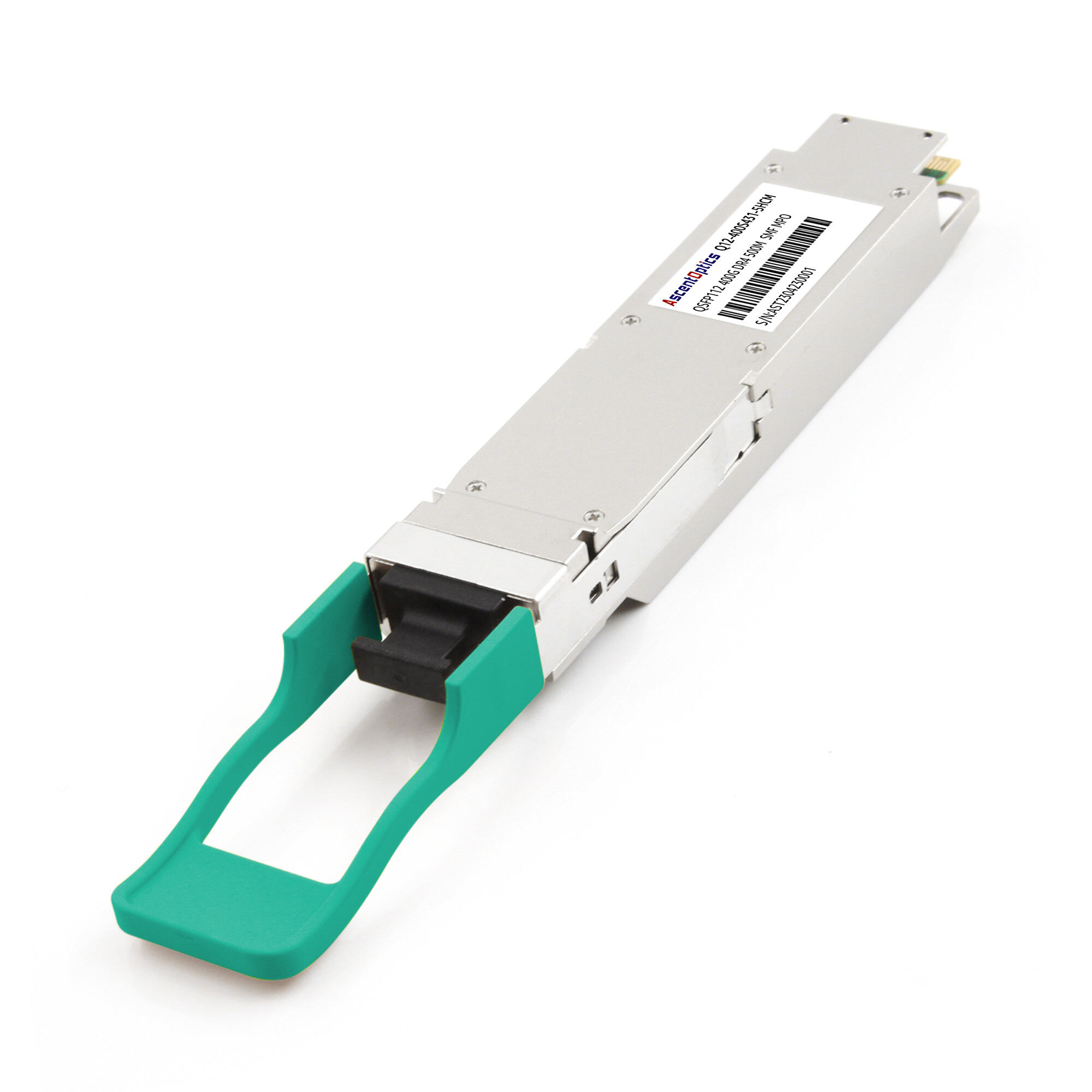
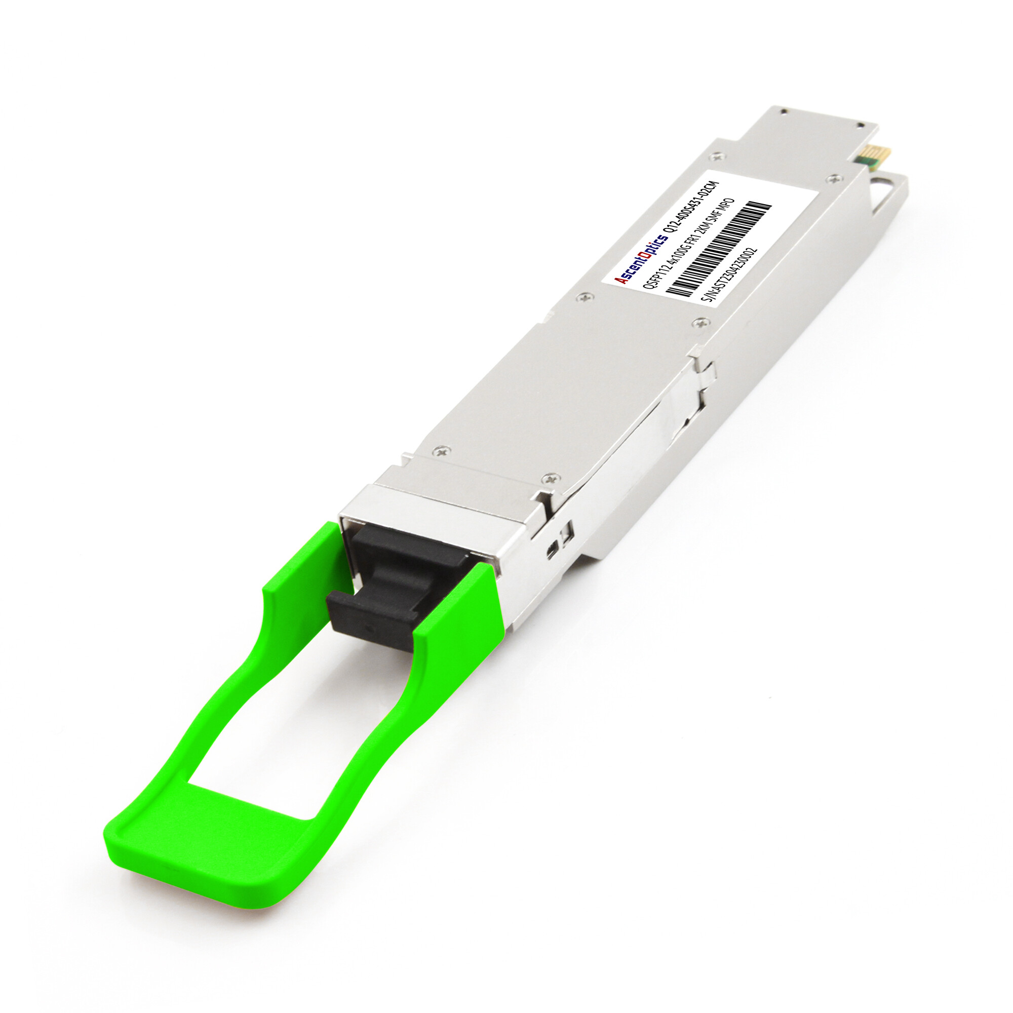
DR4/DR4+: Single-Mode for Leaf-Spine
DR4 modules use 1310nm EML lasers and single-mode fiber to reach 500 meters. DR4+ extends this to 2 kilometers. Both variants use MPO-12 APC connectors and support 4x100G breakout configurations. DR4 is the workhorse for leaf-spine interconnects in modern data centers.
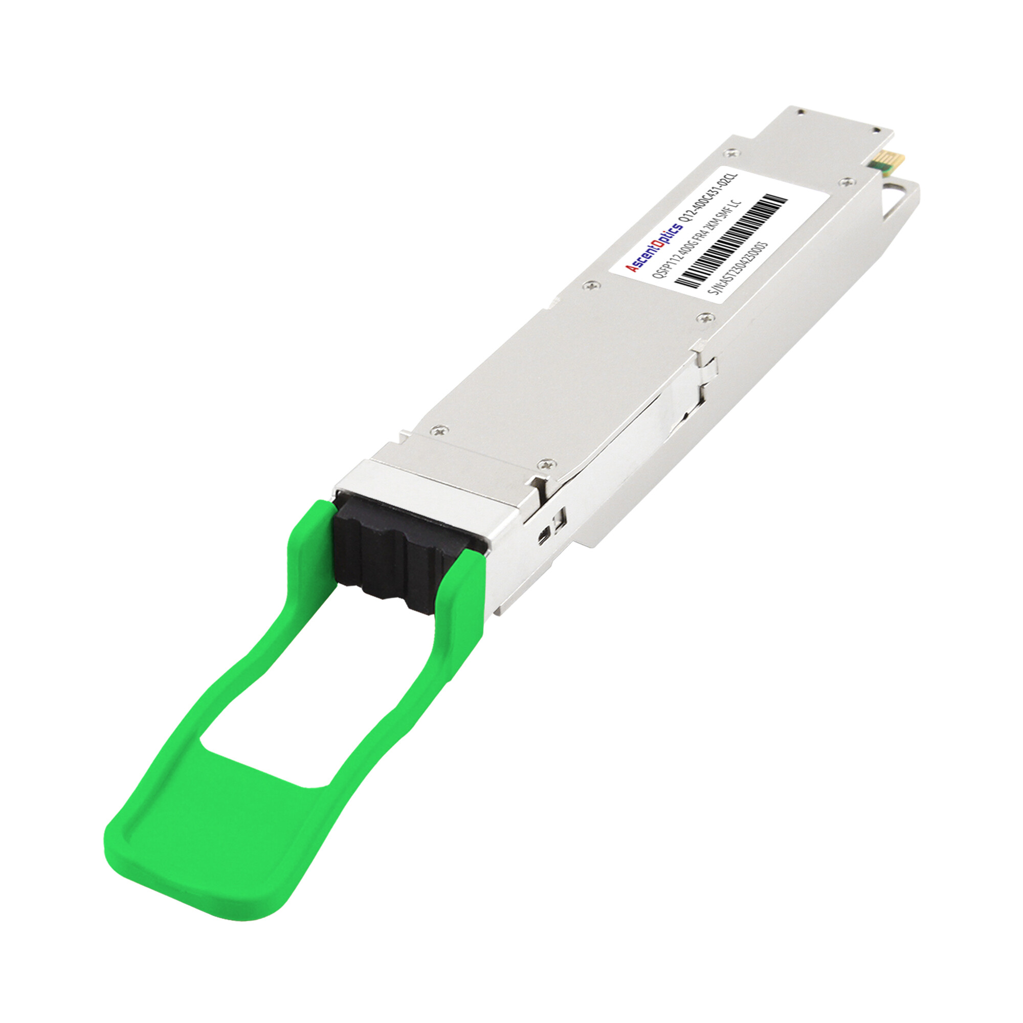
FR4 and LR4: WDM for Campus and DCI
FR4 and LR4 use wavelength-division multiplexing to transmit four lanes over a single duplex fiber pair. FR4 reaches 2 kilometers, while LR4 extends to 10 kilometers. These modules are essential for campus networks, metro connectivity, and data center interconnects where fiber count must be minimized.
Explore our 400G QSFP112 optical transceiver solutions to find options matched to your network architecture and bandwidth requirements.
Why Deploy QSFP112 in Data Centers?
When Elena Vasquez’s team at a European cloud provider planned their next-generation AI training cluster, they evaluated both QSFP-DD and QSFP112 for the 400G leaf-spine fabric. The QSFP-DD modules drew 12W each. The QSFP112 equivalents drew 9W. With 2,048 ports in the first phase, the difference was 6.1 kilowatts. Over a year, that translates to roughly 53,000 kWh in energy savings. The decision was straightforward.
In large-scale AI clusters with thousands of ports, even a small reduction in per-port power consumption can translate into meaningful savings in energy usage and cooling requirements.
Power Efficiency vs. QSFP-DD
QSFP112 modules are often optimized for lower power consumption in platforms designed around 112G electrical lanes. Actual power consumption varies by module type, DSP architecture, and vendor implementation rather than form factor alone. The difference comes from the reduced lane count. Fewer active lanes mean less drive circuitry, lower DSP overhead, and reduced thermal output. At the data center scale, these savings compound quickly.
QSFP112 maintains the compact QSFP form factor. Compared with OSFP-based platforms, QSFP112 enables high front-panel density while retaining the familiar QSFP mechanical footprint. A 1RU switch can support 32 or 64 QSFP112 ports, delivering up to 25.6 Tbps of switching capacity.
Thermal Advantages at Rack Scale
Lower per-module power directly reduces thermal load. At 64 ports per switch, QSFP112 can save 128-256W per switch compared to QSFP-DD. Across a full rack of leaf switches, this reduction can eliminate the need for supplemental cooling. Data centers operating in power-constrained environments benefit significantly.
Simplified 4-Lane Signal Integrity
With only four lanes to route, PCB design is less complex than the eight-lane QSFP-DD alternative. Shorter trace lengths and reduced crosstalk improve signal margins. This simplification can translate to better manufacturing yields and more reliable long-term operation.
Data Center Deployment Scenarios
Top-of-Rack Server Connectivity
QSFP112 SR4 modules are the natural choice for ToR deployments. They connect servers with 400G NICs to Top-of-Rack switches over OM4 or OM5 multimode fiber. Typical distances of 10-30 meters fall well within the SR4 reach. The breakout capability of QSFP112 DR4 also allows a 400G switch port to fan out to four 100G server connections, easing migration from existing QSFP28 infrastructure.
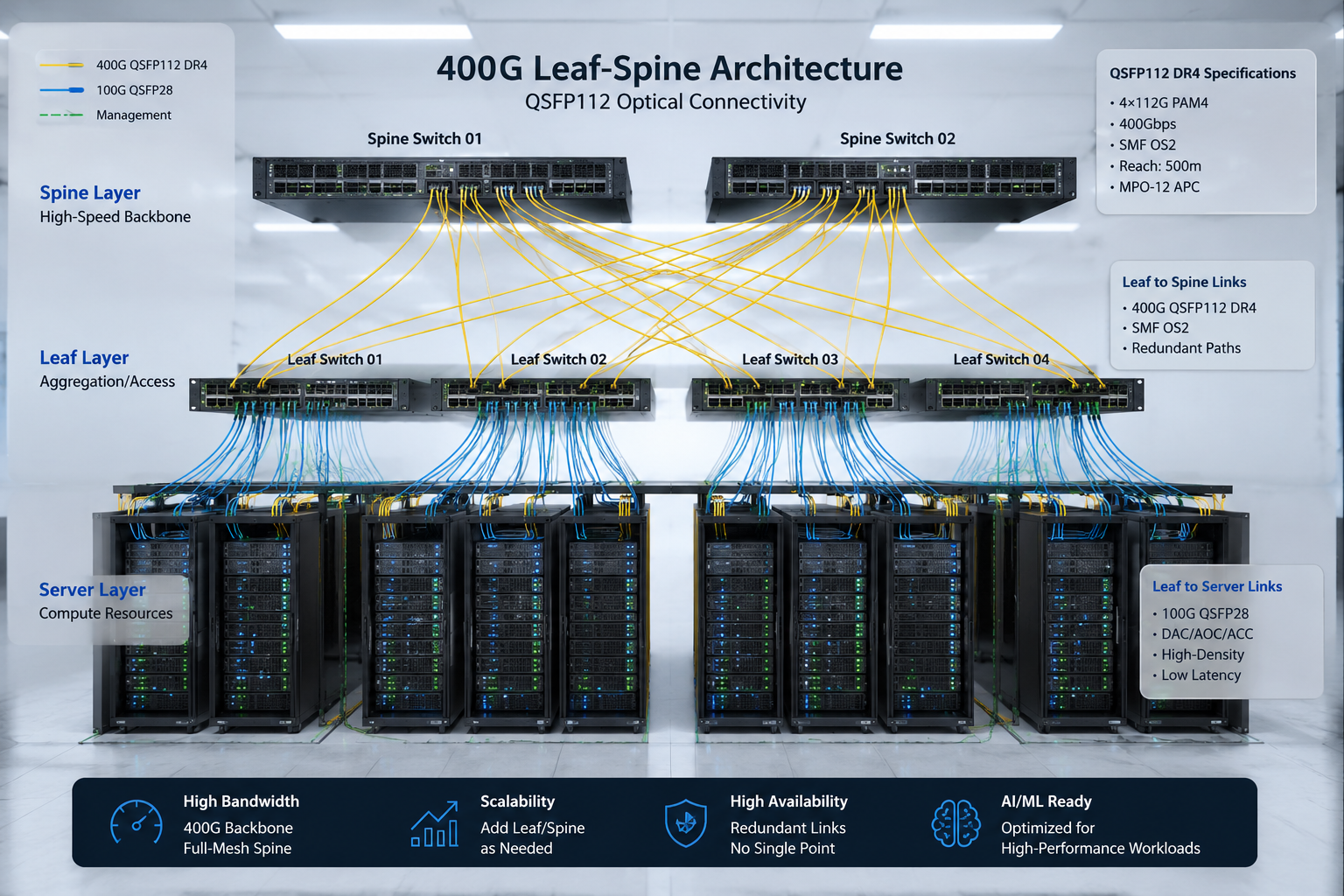
Leaf-Spine Fabric Interconnects
The leaf-spine architecture is the standard for modern data center networks. QSFP112 DR4 modules connect leaf switches to spine switches over single-mode fiber at 500 meters. For larger facilities, DR4+ extends this to 2 kilometers without requiring coherent optics. The 4x100G breakout support enables flexible migration paths, allowing spine switches to connect to both 400G leaf switches and legacy 100G equipment.
AI/ML and HPC Cluster Networking
AI training clusters demand low-latency, high-bandwidth interconnects between GPU servers. QSFP112 is widely used with NVIDIA ConnectX-7 adapters and Quantum-2 InfiniBand platforms. The modules support both Ethernet and InfiniBand protocols, enabling unified backend fabrics for AI workloads. Power efficiency is critical here because GPU servers already consume significant thermal budget.
Modern GPU clusters often use rail-optimized network architectures, where each GPU rail is connected through dedicated 400G links. QSFP112 modules align naturally with these architectures by providing native 4×100G breakout capabilities and compatibility with current-generation InfiniBand and Ethernet AI fabrics.
400G to 4x100G Breakout Configurations
Breakout cables split a single 400G QSFP112 port into four 100G QSFP28 connections. This is essential during migration phases or when connecting heterogeneous equipment. A QSFP112 DR4 module paired with an MPO-12 to 4x duplex LC breakout cable can connect to four separate 100G DR transceivers. Verify that your switch supports breakout mode in software before deployment.
Edge Computing and Regional Nodes
Edge data centers often face strict power and cooling constraints. QSFP112’s lower power draw makes it suitable for these environments. FR4 modules can connect edge nodes to central facilities over 2 kilometers of single-mode fiber, providing high bandwidth without the cost and complexity of coherent optics.
Engineering Considerations for QSFP112 Deployment
Switch and NIC Compatibility
Not all switches with QSFP cages support QSFP112. The host ASIC must include 112G PAM4 SerDes. Key platforms that support QSFP112 include the NVIDIA Spectrum-4 Ethernet switches, NVIDIA Quantum-2 InfiniBand switches, and select Arista 7500R3 series switches. Always confirm with your switch vendor that the specific model and software version support QSFP112 at the required data rate.
Cabling Infrastructure: MPO-12 APC and Duplex LC
SR4 and DR4 modules use MPO-12 APC connectors for parallel optics. Proper polarity management is essential. MPO polarity management should follow the cabling architecture adopted by the data center. Method A, B, and C polarity schemes are all commonly deployed depending on network design requirements. For FR4 and LR4, standard duplex LC connectors apply. Ensure your fiber infrastructure supports the connector types and cleaning procedures required for 400G operation.
Fiber Selection: OM4/OM5 vs. OS2 Single-Mode
For standard 400GBASE-SR4 applications, both OM4 and OM5 typically support reaches up to 50 meters. OM5 may provide additional flexibility for wavelength-division multimode applications. OM5 is recommended for new installations to provide headroom for future upgrades. For DR4, DR4+, FR4, and LR4, an OS2 single-mode fiber is required. Verify that your fiber plant meets the insertion loss budgets specified in IEEE 802.3bs.
Thermal Management and Rack Airflow
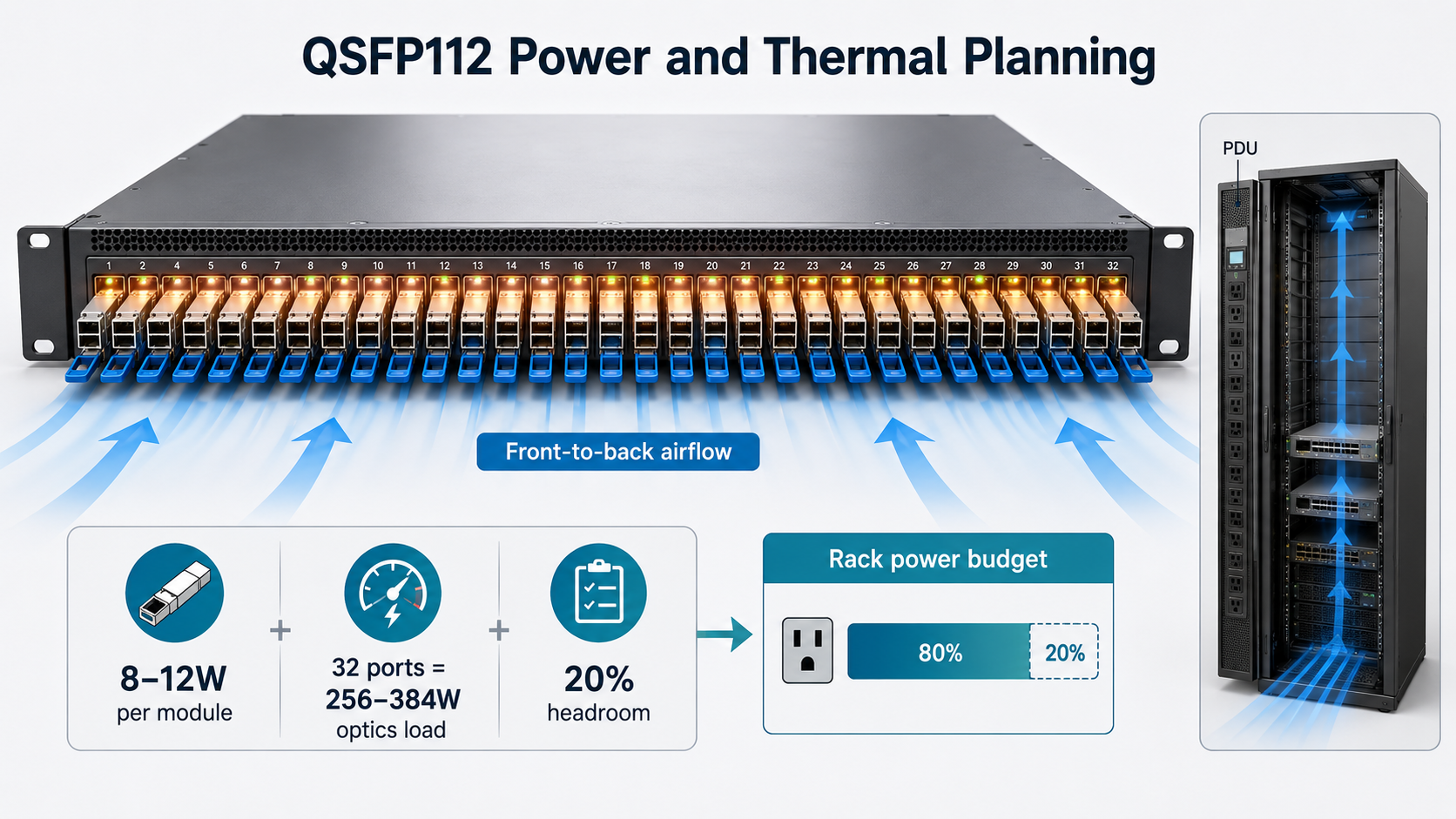
QSFP112 modules dissipate 8-12W each. In a 32-port switch, this adds 256-384W of thermal load. Ensure your rack has adequate front-to-back airflow and that blanking panels prevent hot air recirculation. Modules with flat-top housings rely on riding heat sinks in the switch cage, so maintaining proper cage alignment is critical.
Power Budgeting per Rack Unit
When planning power distribution, calculate total draw including switch base power, module power, and cooling overhead. A 32x400G leaf switch with QSFP112 modules may draw 1,200-1,500W. Plan your rack PDU capacity accordingly, leaving 20% headroom for safety.
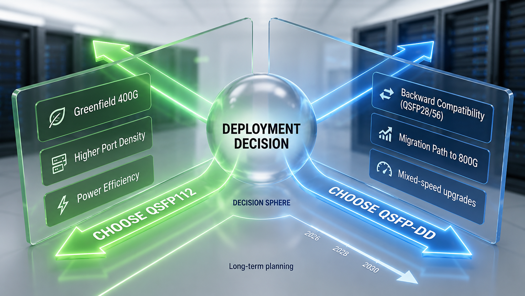
QSFP112 vs. QSFP-DD: When to Choose Which for Your Data Center
The decision between QSFP112 and QSFP-DD depends on your specific deployment context.
Choose QSFP112 When
- •You are building a greenfield 400G deployment without legacy 100G equipment to support.
- •Power efficiency and thermal reduction are top priorities.
- •You are deploying AI/ML clusters with NVIDIA or similar ecosystems.
- •You want maximum port density in a standard QSFP form factor.
- •Your switch ASICs support 112G PAM4 SerDes natively.
Choose QSFP-DD When
- •You need backward compatibility with QSFP28 or QSFP56 modules.
- •You are upgrading brownfield networks with mixed 100G/400G requirements.
- •You want a migration path to 800G through QSFP-DD800.
- •Your switch vendor primarily supports QSFP-DD for 400G.
Decision Framework
| Factor |
QSFP112 |
QSFP-DD |
| Power Consumption |
8-12W |
10-14W |
| Backward Compatibility |
Limited |
Strong (QSFP28/56) |
| Future Scalability |
Capped at 400G |
Path to 800G |
| Port Density |
Higher |
Lower |
| Ideal Use Case |
AI clusters, greenfield 400G |
Mixed-speed upgrades |
For a deeper comparison, see our QSFP112 vs QSFP-DD guide.
Typical QSFP112 Deployment Scenarios
Different QSFP112 transceiver types are optimized for different network architectures, distances, and fiber infrastructures. Selecting the appropriate module can improve network efficiency while minimizing deployment costs.
| Deployment Scenario |
Recommended Module
|
Fiber Type |
Typical Reach
|
Key Benefits |
| Top-of-Rack (ToR) Server Connectivity |
400G SR4
|
OM4/OM5 MMF |
Up to 50m
|
Low-cost, low-latency connectivity within and between adjacent racks |
| Leaf-Spine Fabric Interconnect |
400G DR4
|
OS2 SMF |
Up to 500m
|
Ideal for modern data center fabrics with high port density and scalable bandwidth |
| Large Data Hall or Campus Network |
400G DR4+ / FR4
|
OS2 SMF |
Up to 2km
|
Supports longer links while maintaining efficient 400G transmission |
| Data Center Interconnect (DCI) |
400G LR4
|
OS2 SMF |
Up to 10km
|
Reduces fiber count through WDM technology and enables cost-effective inter-site connectivity |
| AI/ML and HPC Clusters |
400G DR4 / DR4+
|
OS2 SMF |
500m–2km
|
Supports high-bandwidth GPU fabrics and 4×100G breakout architectures |
| Edge Data Centers |
400G FR4
|
OS2 SMF |
Up to 2km
|
Balances reach, power efficiency, and deployment simplicity in space-constrained environments |
Quick Selection Guidelines
For most enterprise and cloud data centers, 400G DR4 has become the preferred choice for leaf-spine architectures because it offers a balance of cost, reach, and scalability. 400G SR4 remains the most economical option for short-reach intra-data-center links, while 400G FR4 and LR4 are better suited for campus and inter-site connections where fiber availability is limited.
For AI and HPC environments built around NVIDIA Spectrum-4 Ethernet or Quantum-2 InfiniBand platforms, 400G DR4 and DR4+ are typically the most widely deployed options due to their compatibility with high-density single-mode fiber infrastructures and breakout configurations.
Future Outlook: QSFP112 to 800G and Beyond
QSFP112 is explicitly a 400G solution. There is no 800G variant because the four-lane architecture cannot scale beyond 4x112G without replacing both transceivers and switch hardware. Organizations choosing QSFP112 should view it as a high-efficiency 400G platform, not a long-term scaling path.
The industry is moving toward 800G through QSFP-DD800 and OSFP form factors, which use eight lanes at 100 Gbps. For data centers that will need 800G within three to five years, QSFP-DD may offer better future-proofing. However, for deployments where 400G meets current and near-term needs, QSFP112 delivers superior efficiency today.
Linear pluggable optics (LPO) and linear drive optics (LDO) are emerging as variants that eliminate DSP inside the module. LPO QSFP112 modules can reduce power consumption to under 8W and cut latency to less than 60 nanoseconds. These variants are particularly promising for AI networking where every watt and every nanosecond matter. Although LPO modules can significantly reduce power consumption and latency, they require stricter host-channel signal integrity and interoperability validation compared with DSP-based optics.
Conclusion
Deploying QSFP112 optical transceivers in data center networks requires careful planning across module selection, power budgeting, cabling, and switch compatibility. The form factor offers clear advantages in power efficiency, port density, and thermal management for greenfield 400G deployments. Network engineers who understand these trade-offs can build more efficient and reliable network infrastructure.
Key takeaways for your next deployment:
- •Match the QSFP112 variant to your distance and fiber type requirements.
- •Calculate power and thermal loads at rack scale, not just per module.
- •Verify switch and NIC compatibility before procurement.
- •Plan cabling infrastructure for MPO-12 APC or duplex LC as required.
- •Evaluate LPO variants for latency-sensitive AI and HPC workloads.
Need help selecting QSFP112 modules? Contact our engineers →
Frequently Asked Questions (FAQ)
Q1:Is QSFP112 compatible with QSFP28 or QSFP56 ports?
A:QSFP112 shares the same mechanical footprint as QSFP28 and QSFP56 modules, but full compatibility depends on the host platform. A switch or NIC must support 112G PAM4 electrical interfaces to operate QSFP112 modules at 400G speeds. While many QSFP112-capable systems can also support QSFP28 and QSFP56 optics, the reverse is generally not true.
Q2:What is the difference between QSFP112 and QSFP-DD?
A:The primary difference lies in the electrical lane architecture. QSFP112 uses four 112G PAM4 lanes to deliver 400G bandwidth, while QSFP-DD traditionally supports eight electrical lanes and offers broader backward compatibility with QSFP28 and QSFP56 ecosystems. QSFP112 is often favored in modern AI and HPC platforms built around native 112G SerDes architectures.
Q3:Which QSFP112 module is best for leaf-spine data center networks?
A:For most leaf-spine deployments, 400G DR4 is the preferred choice. It supports up to 500 meters over OS2 single-mode fiber, provides excellent cost efficiency, and supports 4×100G breakout configurations. For larger facilities requiring longer distances, 400G DR4+ can extend reach to 2 kilometers.
Q4:Is QSFP112 suitable for AI and HPC clusters?
A:Yes. QSFP112 has become widely adopted in AI and HPC environments because it aligns with current-generation 112G SerDes switch ASICs and network adapters. It is commonly deployed in high-performance Ethernet and InfiniBand fabrics that connect GPU servers, storage systems, and accelerator clusters.
Q5:Can QSFP112 support 400G to 4×100G breakout?
A:Yes. Many QSFP112 DR4 and DR4+ modules support 4×100G breakout operation. This allows a single 400G port to connect to four independent 100G links, simplifying migration from existing 100G infrastructure and increasing deployment flexibility.
Q6:Is QSFP112 a future-proof choice for 800G upgrades?
A:QSFP112 is primarily designed for 400G networking. Organizations planning to migrate directly to 800G Ethernet in the near future may prefer platforms based on QSFP-DD800 or OSFP. However, for deployments where 400G bandwidth will remain sufficient for several years, QSFP112 offers an efficient and mature solution with excellent power and thermal characteristics.
Q7:Are LPO QSFP112 modules better than traditional DSP-based optics?
A:LPO (Linear Pluggable Optics) modules can reduce power consumption and latency by eliminating the onboard DSP. However, they require stricter host signal integrity and interoperability validation. Traditional DSP-based QSFP112 modules remain the most widely deployed option due to their greater compatibility and operational flexibility.
Post Views: 865