Maria Santos had considered herself well-prepared. In March 2025, her team ordered 500 QSFP28 SR4 transceivers for a new data center build in Frankfurt. The modules arrived on time, passed visual inspection, and seated perfectly in the switch ports. It was only then that they discovered the cabling contractor had installed OS2 single-mode fiber throughout the facility. SR4 modules require multimode fiber. The entire shipment became useless, forcing an emergency rush order of LR4 optics that cost an additional $47,000.
This is why understanding how to choose the right QSFP28 module matters. The correct choice depends on matching fiber type, reach distance, switch compatibility, power budget, breakout requirements, and overall architecture.
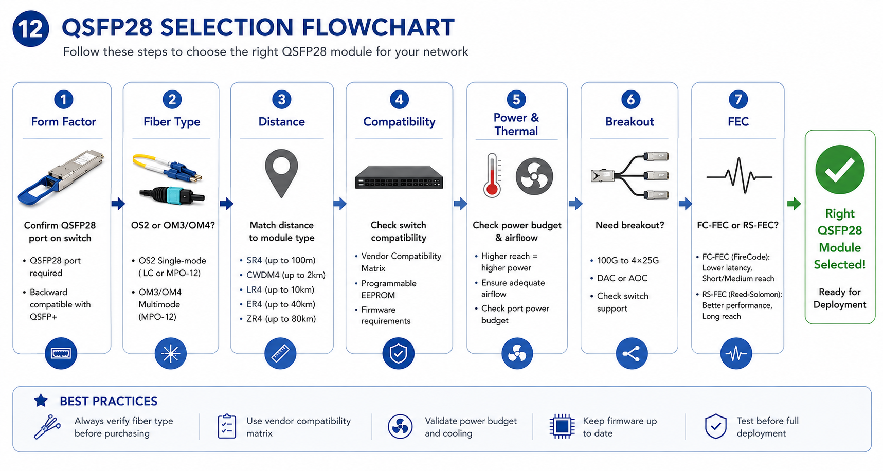
This guide provides a systematic selection process to help you choose the right QSFP28 module every time. You will learn how to verify form factor compatibility, match fiber and distance requirements, validate switch compatibility, consider thermal constraints, and avoid costly deployment mistakes.
Need help selecting the right module? Explore Ascent Optics’ QSFP28 transceiver portfolio or contact our engineers for a free compatibility review.
Start With the Basics: Is QSFP28 the Right Form Factor?
Before comparing modules, confirm that QSFP28 is the correct form factor for your application. This is one of the most common — and easily avoidable — mistakes.
QSFP28 Form Factor and Port Compatibility
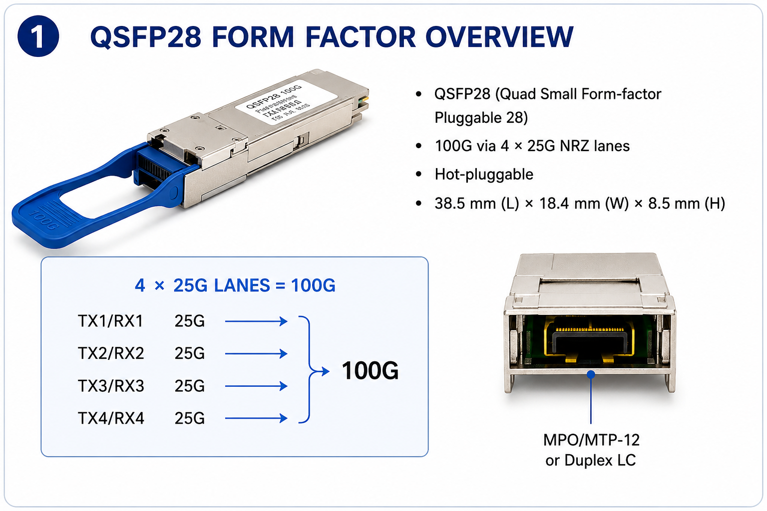
QSFP28 (Quad Small Form-factor Pluggable 28) is a hot-pluggable optical transceiver that delivers 100G Ethernet using four 25G NRZ lanes. It has the same physical size as QSFP+ (40G) but requires switch ASICs that support 25G signaling. Most modern 100G switches come with native QSFP28 ports.
Use QSFP28 modules only if your switch or router has QSFP28 ports. While QSFP28 modules will physically fit into QSFP+ ports in many cases, they are not interchangeable due to signaling differences. Most QSFP28 ports, however, are backward-compatible with QSFP+ modules.
When QSFP+ or QSFP-DD Might Be Better
The support of QSFP+ in the native mode is acceptable given it to run 40 Gb definitely; QSFP-DD is also in stock for 400GB. This is the way out if you are deploying a next-generation switch. Here comes just one best part about QSFP-DD ports. Indeed, most QSFP-DD ports are genuinely designed not only for QSFP-DD but also for QSFP28 modules, meaning the switch modifications would only be needed if you planned to directly perform 400 Gb.
For a deeper comparison of form factor compatibility, see our QSFP28 vs QSFP+ guide.
Step 1 — Determine Your Fiber Type
Fiber type is the most critical first decision. Getting this wrong renders all other choices irrelevant.
Single-Mode Fiber (OS2) Options
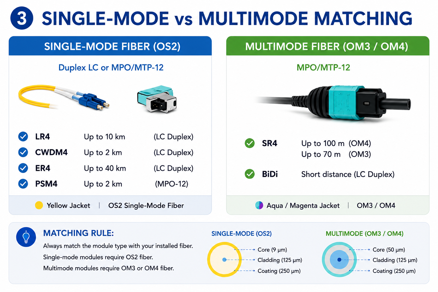
If your infrastructure uses duplex LC or MTP/MPO-12 single-mode fiber, select a single-mode QSFP28 module. Common options include:
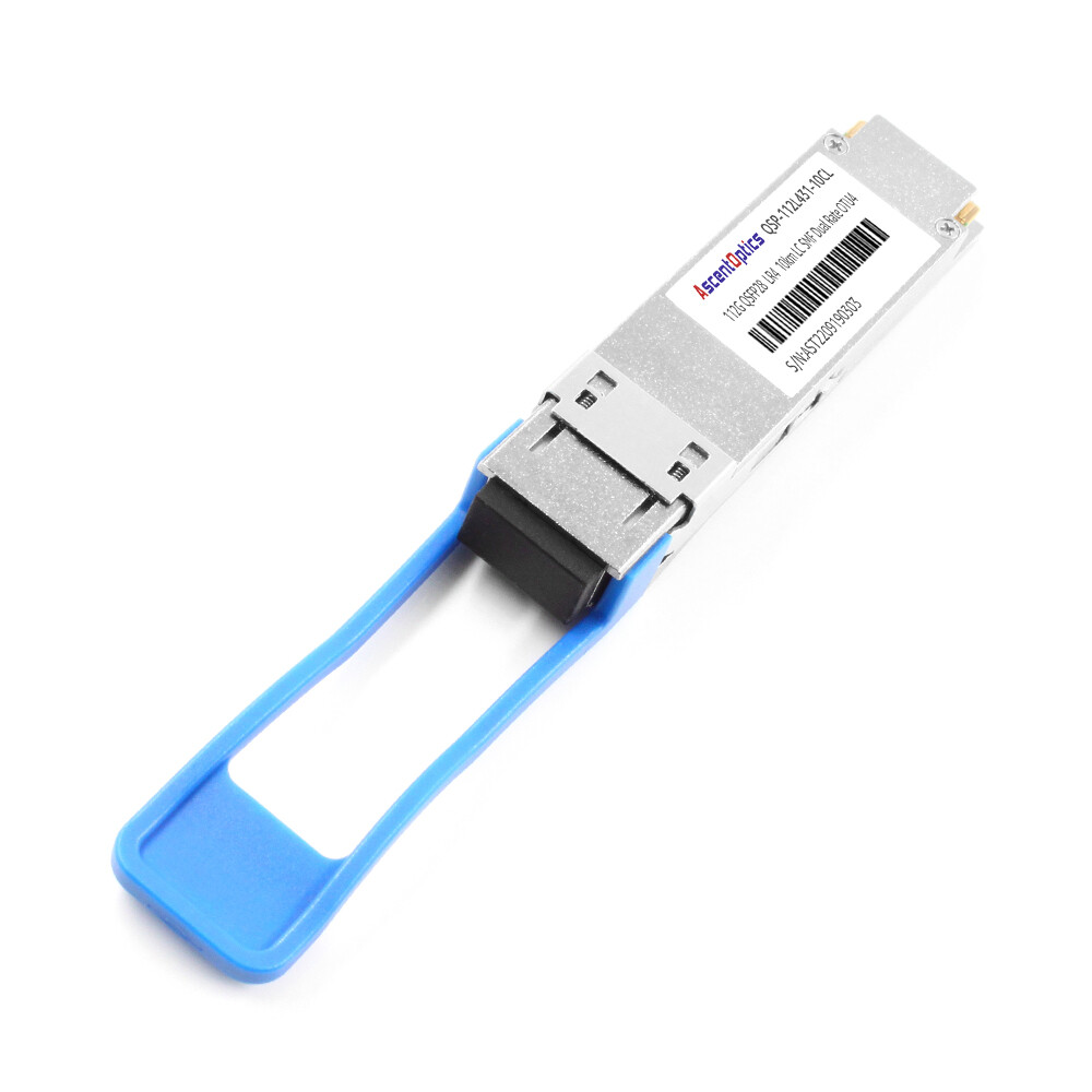
- •LR4: Up to 10 kilometers over duplex LC OS2
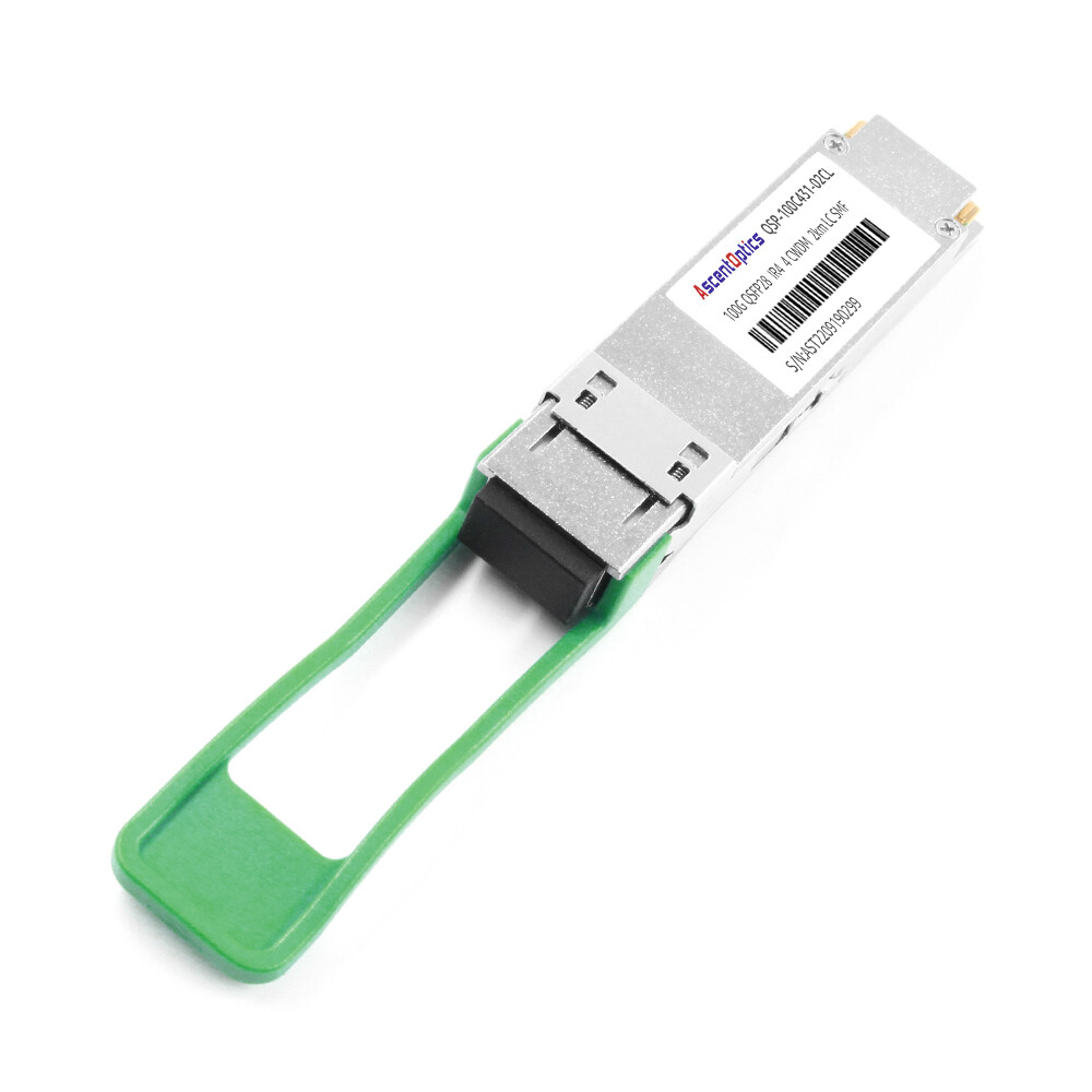
- •CWDM4: Up to 2 kilometers over duplex LC OS2
- •ER4: Up to 40 kilometers over duplex LC OS2
- •PSM4: Up to 2 kilometers over MTP/MPO-12 OS2
Single-mode fiber supports every long-reach module type. It is also the safest choice for future-proofing because it will carry 400G and 800G signals without replacement.
Multimode Fiber (OM3/OM4) Options
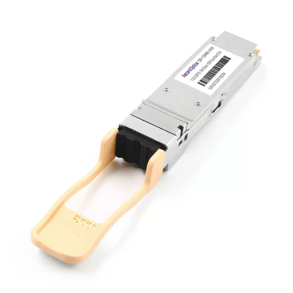
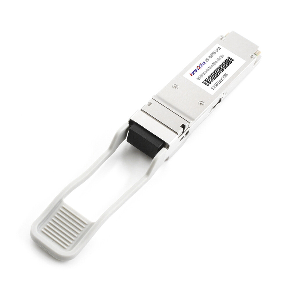
For multimode fiber, the primary option is SR4, which uses MTP/MPO-12 connectors and supports up to 100m on OM4 or 70m on OM3. Some short-reach BiDi versions using duplex LC multimode fiber are also available for even shorter distances.
Maria Santos learned this lesson the hard way. Her team ordered SR4 modules assuming “fiber is fiber.” The contractor had installed OS2 single-mode fiber instead. Multimode SR4 optics cannot operate over single-mode fiber. They had to choose between replacing 80 km of fiber or replacing 500 transceivers. They chose the latter, turning a $35K order into an $82K emergency.
The Fiber Mismatch Trap
The most expensive selection error is the purchase of modules before the fiber type installed is confirmed. Do not trust on the documentation to do this. You need to use an Optical Time Domain Reflectometer (OTDR) or use at least a fiber identifier to confirm if your plant is single-mode or multimode. Also, check the jacket color: OM3 is typically aqua, OM4 is often aqua or magenta, OS2 is yellow.
Step 2 — Match Distance to Module Type
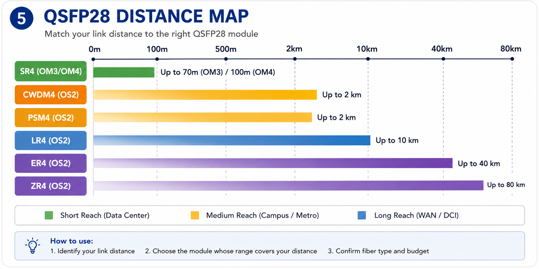
Once fiber type is confirmed, match the link distance to the appropriate module
Short Reach: SR4 and SR10
QSFP28 SR4 stands as the short reach option for data center links over OM4 multimode fiber up to 100 meters long with standard four 25G lanes that bind MTP/MPO-12 connectors. Pushing SR4 into even shorter links over OM3, within 70m from either end, however, will work, but OM3, going beyond 70 meters, will never work.
Medium Reach: CWDM4 and PSM4
For interconnecting links on campus or between 100 meters and 2 kilometers over single-mode fiber, CWDM4 and PSM4 are economical solutions. CWDM4 carries four wavelengths over a single fiber pair duplex using LC connectors, and PSM4 uses parallel optics over MTP/MPO-12 single-mode fiber. CWDM4 is commonly preferred for duplex LC environments while PSM4 could be a bulky but cost-effective solution for parallel fiber deployments.
Long Reach: LR4 and ER4
A compact form factor supports 2x100G link over multiplex fiber for 2x100G switch/router 400GBASE-LR8, extending the link budget for hyperscroll and DCO, and supporting external amplifiers for metro-high access and data center interconnects.
Extended Reach: ZR4 and Coherent Options
Beyond 40 km, QSFP28 ZR4, and the coherent 100G modules can go up to 80 km +. They are specially meant to be used for telecom and long-haul applications and consume even more power in comparison to other setups, typically requiring more careful dispersion management.
Distance Selection Quick Reference Table
| Module |
Fiber Type
|
Connector |
Max Distance |
Best For
|
| SR4 |
OM4 multimode
|
MTP/MPO-12 |
100 m |
Data center spine-leaf
|
| SR4 |
OM3 multimode
|
MTP/MPO-12 |
70 m |
Legacy data center links
|
| CWDM4 |
OS2 single-mode
|
Duplex LC |
2 km |
Campus / metro
|
| PSM4 |
OS2 single-mode
|
MTP/MPO-12 |
2 km |
Parallel fiber deployments
|
| LR4 |
OS2 single-mode
|
Duplex LC |
10 km |
DCI / WAN aggregation
|
| ER4 |
OS2 single-mode
|
Duplex LC |
40 km |
Regional networks
|
| ZR4 |
OS2 single-mode
|
Duplex LC |
80 km |
Telecom long-haul
|
For a deeper dive into each module type, read our QSFP28 module types guide.
Step 3 — Verify Switch and Platform Compatibility
Module selection does not end with fiber and distance. The module must also be accepted by your switch.
Why MSA Compliance Is Not Enough
If a module is found inside a switch, it does not imply an MSA-compliant guarantee. Although the module and the switch can communicate according to the same electrical interface and signaling, it does not have any bearing upon whether the switch will accept the module. Various switch vendors conduct a test on EEPROM configuration and onboard module tests. Indeed, if the switch finds that the module does not advertise a valid vendor ID, it may choose either not to bring up the link at all or to disable digital diagnostics.
David Chen learned this in Singapore. For a Cisco Nexus 9300 deployment, he bought QC-specified third-party modules for QSFP28 CWDM4. These modules physically seated properly, but only one out of the four links would come up. After eight hours of cable troubleshooting, fiber cleaning, and port swapping one after another, David discovered that the other issue was the fact that the firmware that he was running required vendor-coded optic modules. We found that the third-party modules worked fine in the Arista switch in the lab, but not in the Cisco chassis. Downgrading the firmware solved two links, but the other two had to be replaced with OEM-coded transceivers.
How to Check Vendor Compatibility Matrices
Keep referring to your supplier’s optic compatibility matrix before placing a substantial order. For instance, look for Cisco’s Optics-To-Device Compatibility Matrix, Arista’s Transceiver Guide, or Juniper’s Hardware Compatibility Tool (HCT). NVIDIA (Mellanox) publishes LinkX interoperability guides.
If you’re going down the third-party optic road, it all comes down not just to the module or item part number, but also the minimum switch memory version that has to be there.
Third-Party Optics vs OEM Modules
OEM modules from Arista, Juniper, or Cisco come at a higher price but present the lowest compatibility risk. Third-party modules from respected manufacturers are available in the market under 50%-70% cheaper and offer nearly identical levels of performance, but they will require extra effort when verifying switch whitelist support. Some third-party suppliers offer pre-coded relative modules for specific switch platforms that decrease the risk painlessly.
For detailed switch platform guidance, see our QSFP28 compatible switches guide
Step 4 — Factor in Power and Thermal Budgets
Not all QSFP28 modules consume the same amount of power. In high-density switches, power and thermal limits can affect your module choice.
Typical QSFP28 Power Consumption by Module Type
| Module Type |
Typical Power Draw |
| SR4 |
3.5 W to 4.5 W |
| CWDM4 |
3.5 W to 4.5 W |
| LR4 |
4.0 W to 5.0 W |
| ER4 |
4.5 W to 5.5 W |
| ZR4 / Coherent |
5.5 W to 15 W+ |
High-Density Switch Thermal Considerations
If anything, it may be a 64-port fan QSFP28 switch loaded to the point where it consumed over 350 watts with optics only if 5.5W loads each. The chassis itself could draw as much as 600 to 800 watts. If the rack cooling is designed just around low-density 40G deployments, a full 100G load may fully stretch the thermal margins.
When Power Draw Affects Your Choice
If you are sweating every watt and inch of your expansion capability, it may not be a further reach to wonder whether a lesser-powered class of optics can get you there. For instance, CWDM4 has a power consumption profile under that of ER4. CWDM4 would yield a manageable thermal margin for sub-2-kilometer links.
Step 5 — Decide on Breakout Architecture
Many deployments use 100G QSFP28 ports in breakout mode to connect to 4×25G SFP28 server ports.
Native 100G vs 4×25G Breakout
The switch at the leaf layer would connect to servers that transmit with 25G NICs; indeed, splitting out the four lanes of 25G into four separate SFP28 server ports might be an advantage. Typically, 25G QSFP28 can be used only in breakout mode.
Your module selection is different in each case:
- •Native 100G:Use a standard QSFP28 SR4, LR4, or CWDM4 module
- •4×25G breakout:Use a QSFP28-to-4×SFP28 breakout cable (DAC or AOC) instead of a traditional optical transceiver
QSFP28-to-SFP28 Breakout Cable Selection
Breakout cables come in two main types:
- •DAC (Direct Attach Copper):Passive copper cables up to 3-5 meters. Low cost, low power, but limited distance.
- •AOC (Active Optical Cable):Fiber-based cables up to 30-100 meters. Higher cost and power but much longer reach.
Remember: QSFP+ breakout cables split 40G into four 10G SFP+ links. QSFP28 breakout cables split 100G into four 25G SFP28 links. They are not interchangeable.
Michelle ordered enough QSFP28 SR4 modules for leaf switches to fan out to 25G server ports. That is not quite what is needed here. What she needed were QSFP28-to-4×SFP28 breakout AOCs. SR4 modules are never good for breakout architecture: consequently we had to rush-order 400 breakout cables delaying the server cutover by ten days and blowing the optical budget.
Breakout Port Verification on Your Switch
No one owns the QSFP28 port, which may function as a breakout port. No one may determine how or where this pioneering technology may function; rather, one must refer to the directory for all stipulated locations.
Step 6 — Validate FEC and Signaling Requirements
Forward Error Correction (FEC) is a layer 1 mechanism that corrects bit errors on high-speed links. FEC mismatches between endpoints are a common cause of link flapping and packet loss.
FC-FEC vs RS-FEC: What Your Module Needs
Most QSFP28 modules use one of two FEC modes:
- •FC-FEC (Firecode FEC):A lighter correction scheme used for shorter-reach modules like SR4 and some DACs
- •RS-FEC (Reed-Solomon FEC):A stronger correction scheme typically required for LR4, ER4, and many breakout configurations
Avoiding FEC Mismatches
Match the FEC setting on both ends of the link. If one side expects RS-FEC and the other is set to FC-FEC or no FEC, the link may come up briefly and then flap repeatedly. Check your switch configuration and NIC settings before deployment. Some platforms auto-negotiate FEC, but cross-vendor links often require manual alignment.
Need help verifying FEC settings for your switch? Contact our optical networking experts for configuration guidance.
QSFP28 Selection Decision Matrix
Here is a practical decision matrix to match your application to the right module:
| Application |
Recommended Module |
Fiber |
Distance |
Typical Use Case |
| Data center spine-leaf |
SR4 |
OM4 |
≤100 m |
East-west traffic |
| Legacy OM3 data center |
SR4 |
OM3 |
≤70 m |
Upgraded 40G plant |
| Campus / metro link |
CWDM4 |
OS2 |
≤2 km |
Building interconnect |
| Parallel fiber deployment |
PSM4 |
OS2 |
≤2 km |
MPO-12 infrastructure |
| DCI / WAN aggregation |
LR4 |
OS2 |
≤10 km |
Telecom backhaul |
| Regional network |
ER4 |
OS2 |
≤40 km |
City-wide connectivity |
| Long-haul telecom |
ZR4 |
OS2 |
≤80 km |
Transport network |
| 25G server breakout |
QSFP28-to-4×SFP28 DAC/AOC |
Varies |
≤100 m |
Leaf-to-server links |
Common QSFP28 Selection Mistakes
Even experienced network engineers make these mistakes. Here is how to avoid them.
Choosing SR4 for OS2 Fiber
SR4 is a multimode module. It will not work on OS2 single-mode fiber. If you have single-mode fiber, choose CWDM4, LR4, or another single-mode module.
Ignoring Vendor Whitelists
MSA compliance does not equal switch compatibility. Always verify your switch vendor’s compatibility matrix or use pre-coded third-party optics.
Forgetting Breakout Cable Compatibility
If your servers use 25G SFP28 ports, you need QSFP28-to-4×SFP28 breakout cables, not standard QSFP28 transceivers. And you need switch ports that support breakout mode.
Underestimating Power and Cooling
A fully loaded high-density switch with power-hungry modules can exceed your rack thermal budget. Recalculate cooling requirements before committing to an all-100G deployment.
Conclusion
Knowing how to choose QSFP28 modules is not about memorizing part numbers. It is about following a systematic framework: confirm the form factor, verify the fiber type, match the distance, check switch compatibility, account for power and thermal limits, and validate breakout and FEC requirements.
Key takeaways:
- •Fiber type comes first.A mismatch here makes every other specification irrelevant.
- •MSA compliance does not guarantee switch compatibility.Always verify vendor whitelists.
- •Breakout architecture changes your product choice.QSFP28-to-4×SFP28 breakout cables are not the same as standard transceivers.
- •Power and thermal matter in high-density deployments.A fully loaded switch can draw hundreds of extra watts.
- •Match FEC settingson both ends of every link to avoid flapping.
Ready to select the right QSFP28 module? Explore Ascent Optics’ QSFP28 transceiver solutions and request a quote for your project. For broader 100G context, read our QSFP28 transceiver guide. And if you are planning for 400G, see our guide on how to choose QSFP-DD modules.
Frequently Asked Questions
Q1. Can I use any QSFP28 that follows an MSA standard in my switch?
Possibly not. EEPROM codes from the vendors can be enforced by several switches. The compliance of an MSA means only that a company will have to have specific physical and electrical compatibility; however, a switch may still refuse to take up if it does not report a vendor ID that the switch knows to expect.
Q2. How do I know if I need breakout cables or standard modules?
Use standard QSFP28 transceivers for 100G-to-100G connections. Use QSFP28-to-4×SFP28 breakout cables when connecting to 25G SFP28 server ports.
Q3. Which is better — single-mode or multimode fiber for QSFP28?
Single-mode (OS2) is better for future-proofing as it supports higher future speeds (400G/800G). Multimode is cost-effective for short-reach data center links (≤100m).
Q4. How are CWDM4 and LR4 different?
CWDM4 travels 2 kilometers at the very best and is usually 30% to 50% cheaper than LR4, which can be transported over 10 kilometers. Based on distance, it may likely to be cheaper in case one puts color under 2 kilometers for the CWDM4.
Q5. Don’t the QSFP28 modules work in the QSFP-DD ports?
Yes, they do. Most common QSFP-DD ports accommodate QSFP28 modules by default, allowing you to go up to 400G-ready switches today or have 100G optics during the transition.
Q6. In terms of power consumption, what will a QSFP28 module consume?
QSFP28 module power consumption can vary from about 3.5W to 5.5W depending on the kind of module being used. Coherent and ZR4 modules have been known to consume a fair bit more. In a high-density switch configuration, power consumption is an issue with regard to thermal restrictions.
Post Views: 886