An optical module is a connecting module that serves as an optical-electrical conversion device. At the transmitter end, it converts electrical signals into optical signals, which are then transmitter through optical fibers. At the receiver end, the optical signals are reconverted into electrical signals.
An optical module is composed of optoelectronic components, functional circuits, and optical interfaces. The optoelectronic components consist of both transmitting and receiving elements.
Transmitting Section: After processing input electrical signals at a specific data rate using an internal driver chip, it drives a semiconductor laser diode (LD) or light-emitting diode (LED) to emit a modulated optical signal at the corresponding data rate. It includes an internal automatic power control circuit (APC) to maintain the stability of the output optical signal power.
Receiving Section: Optical signals at a specific data rate are input into the module and are converted into electrical signals by the optical detection diode. After passing through a front-end amplifier, the corresponding data rate electrical signals are output.
Here are some of the key performance metrics used to measure the performance of optical modules (The following content is expected from Huawei documentation):
Optical Transmitter Transmitter:
Average transmit power
The average transmitted optical power refers to the optical power output of the light source at the transmitting end of the optical module under normal operating conditions, and can be understood as the intensity of light.
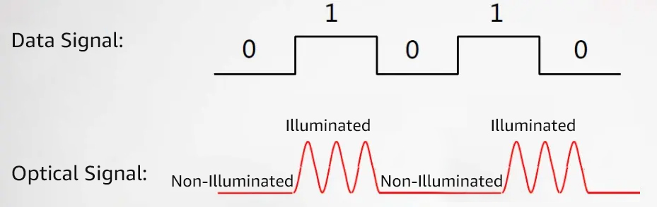
The transmitted optical power is related to the proportion of “1s” in the transmitted data signal; the more “1s” there are, the higher the optical power.
When the transmitter sends a pseudo-random sequence signal, with “1s” and “0s” roughly evenly distributed, the power measured in this case is the average transmitted optical power, measured in dBm.
Extinction ratio
The extinction ratio is defined as the minimum value of the ratio of the average optical power emitted by the laser under full “1” code modulation to the average optical power emitted under full “0” code modulation, under all modulation conditions, measured in dB.
When converting electrical signals into optical signals, this process is carried out by the laser diode in the transmitting portion of the optical module, which modulates the optical signal according to the input signal’s data rate.
The average optical power under full “1” code modulation represents the average power of the laser’s emission, while the average optical power under full “0” code modulation represents the average power of the laser when it is not emitting light. The extinction ratio characterizes the ability to distinguish between o and 1 signals, and, therefore, can be considered as a measure of the laser’s operational efficiency. The typical minimum range for extinction ratio is between 8.2dB to 10 dB.
The central wavelength of optical signal
In the emission spectrum, the wavelength corresponding to the midpoint of the line segment connecting the 50% maximum amplitude value. Different types of lasers or even two lasers of the same type may exhibit variations in their central wavelengths due to factors such as manufacturing processes, production variations, and even different operating conditions for the same laser.
Generally, manufacturers of optical components and optical modules provide users with a parameter, which is the central wavelength (e.g., 850nm). This parameter typically comes with a specified range. Currently, the commonly used central wavelengths for optical modules primarily fall into three main categories: 850nm wavelength, 1310 wavelength, and 1550nm wavelength.
Optical Module Receive:
Overload optical power
The overload optical power, also known as saturation optical power, refers to the maximum input average optical power that the receiving end component can receive under certain bit error rate conditions, measured in dBm.
It’s important to note that optical detectors can experience photoelectric current saturation a certain amount of time to recover, resulting in decreased reception sensitivity. This can lead to signal misinterpretation and the occurrence of bit errors.
Simply put, exceeding the overload optical power can potentially damage the equipment. In practical use, it’s important to avoid exposing the equipment to intense light to prevent exceeding the overload power.
Receiver sensitivity
Receiver sensitivity refers to the minimum average input optical power that the receiving end component of an optical module can receive under a certain bit error rate condition. If transmitted optical power refers to the optical intensity at the sending end, then receiver sensitivity refers to the optical intensity that the optical module can detect. The unit is dBm.
In general, under normal circumstances, the higher the data rate, the lower the reception sensitivity. This means that a higher minimum received optical power is required, and it also places greater demands on the components of the optical module receiver.
Receive Optical Power
The received optical power refers to the average optical power range that the receiving end component of an optical module can receive under certain bit error rate conditions, and is measured in dBm. The upper limit of received optical power is the overload optical power, and the lower limit is the maximum receiver sensitivity.
In summary, when the received optical power is lower than the receiver sensitivity, it may not be able to receive the signal properly because the optical power is too weak. Conversely, when the received optical power exceeds the overload optical power, it may also result in the inability to receive the signal correctly due to the presence of bit errors.
The key performance metrics that affect the performance of optical modules include average transmit optical power, extinction ratio, optical signal central wavelength, overload optical power, receiver sensitivity,and received optical power. By checking whether these values are within their normal range, you can assess the performance of the optical module.
What factors affect the transmission distance of optical modules?
In fact, the transmission distance of optical modules is mainly limited by both loss and dispersion.
The reason for loss is that, during the transmission of light in optical fibers, there is a loss of optical energy due to the absorption, scattering, and leakage of the medium, and this energy dissipates at a certain rate as the transmission distance increases.
Loss constraints can be estimated using the formula: Loss-limited distance = (Transmit optical power – Receiver sensitivity)/ Fiber attenuation. The greater the loss, the shorter the transmission distance of the optical module. And conversely, the lower the loss, the longer the transmission distance.
The primary cause of dispersion is the unequal velocities at which electromagnetic waves of different wavelengths propagate in the same medium. This leads to different wavelength components of the optical signal arriving at the receiver at different times due to cumulative transmission distances, resulting in pulse broadening and the inability to distinguish signal values.
How to realize higher transmit data rate?
-
Adding the number of wavelength
The process of combining optical signals of different wavelengths into a single optical fiber for transmission, and subsequently, using a demultiplexer to separate these signal back into their original multiple optical waveforms, is commonly referred to as Wavelength Division Multiplexing (WDM) technology.
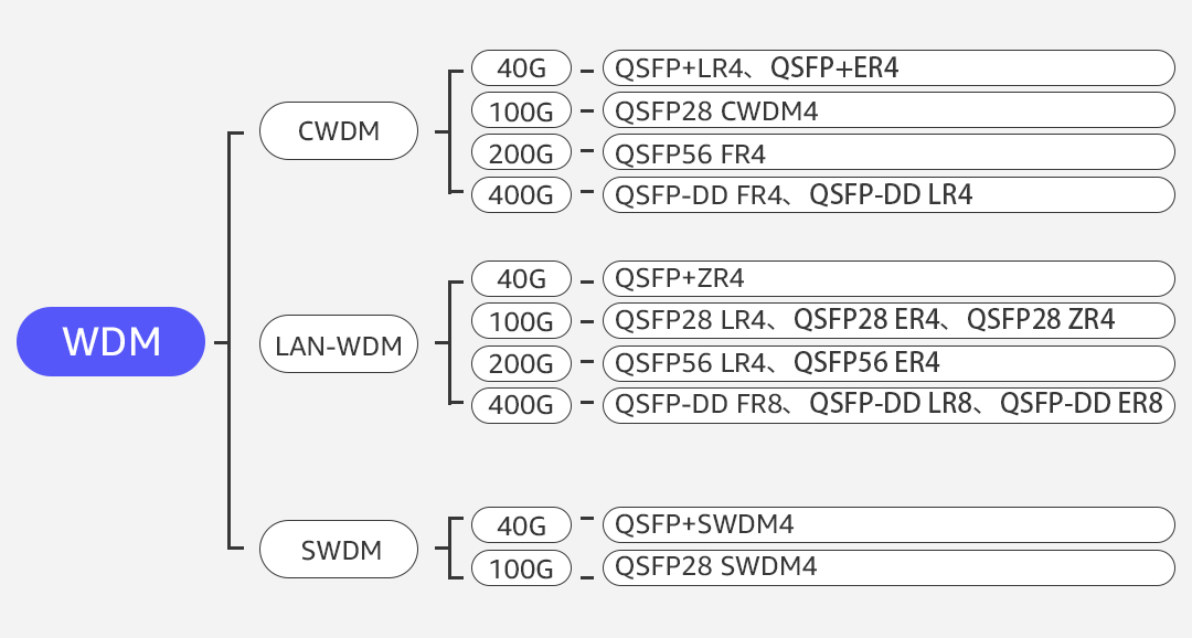
Depending on the wavelength spacing, optical modules may utilize technologies such as CWDM, LWDM, and SWDM.
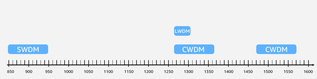
CWDM, which stands for Coarse Wavelength Division Multiplexing, is a technology with a wavelength rang between 1270nm and 1610nm, with a wavelength spacing of 20nm. It allows for the multiplexing of approximately 8 to 16 wavelength on the same optical fiber. Representative optical modules include QSFP+ LR4 and QSFP28 CWDM4.
LWDM, or Long Wavelength Division Multiplexing, is a technology that operates in the wavelength range of 1269nm to 1332nm, falling within the O-band. It has a wavelength spacing of 4nm, with working wavelengths typically set at 1295nm, 1300nm, 1304nm, and 1309nm. Representative optical modules for LWDM include QSFP28 LR4, QSFP28 ER4, and QSFP28 ZR4, among others.
SWDM, or Short Wavelengt4h Division Multiplexing, is a technology that that operates within the wavelength rang of 850nm to 950nm, with a wavelength spacing of 30nm. It utilizes four wavelength bands with windows at 850nm, 880nm, 910nm, and 940nm. Representative optical modules for SWDM include multi-mode 40G SWDM4 and 100G SWDM4.
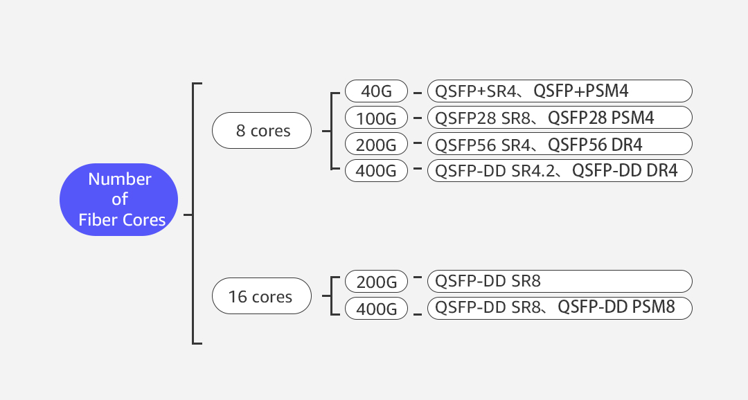
Increase the number of signal transmission channels
By increasing the number of signal transmission channels and utilizing multiple identical wavelengths for signal transmission, it is referred to as parallel optics technology. It operates at working wavelengths of 850nm and 1310nm, providing an economical and efficient solution for 4x 25G, 4x 50G, and 8x 50G applications. Representative optical modules for parallel optics include QSFP+ SR4, QSFP28 SR4, and QSFP-DD SR4, among others.
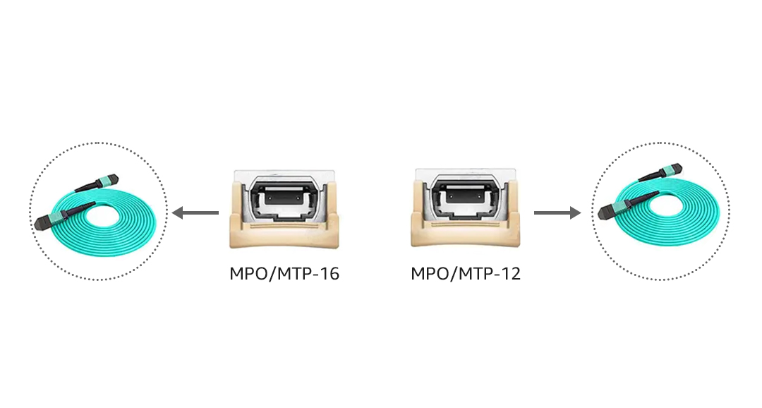
The optical module optical ports come in 12-core and 16-core versions, with corresponding optical fiber connectors MPO-12 and MPO-16.
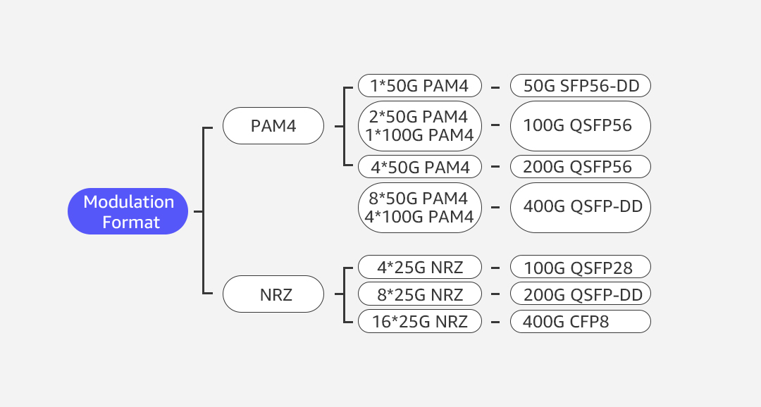
Increasing single-channel data rate – Modulation Format
PAM4 (Pulse Amplitude Modulation 4-Level) and NRZ (Non-Return-to-Zero) are currently crucial and fundamental technologies in the filed of optical communication. As a next-generation high-speed signal interconnect transmission technology, PAM4 achieves higher data transmission rates per signal channel within a unit of time by employing more signal levels. With the same number of channels and existing optical devices, the network interface rate can be doubled by upgrading the internal chipsets of optical modules. Representative optical modules include 50G SFP56-DD SR (1x 50G PAM4), 200G QSFP56 FR4 (4x 50G PAM4), and 400G QSFP-DD SR8 (8x 50G PAM4).
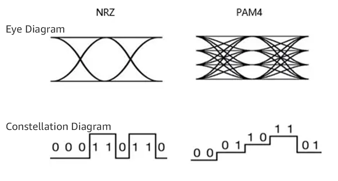
PAM4 signals use two additional voltage levels for signal transmission compared to traditional NRZ signals, resulting in a bit rate that is twice as fast as NRZ signals within the same symbol period.
Post Views: 4,629


