Low-cost light source makes multi-mode fiber to be the most cost-effective solution for short-range transmission. However, due to the high material dispersion at short wavelengths (850 nm), the increase in fiber bandwidth cannot further enhance the transmission capacity and transmission distance. The evolution to longer wavelengths and the use of WDM can increase the transmission capacity of a single fiber by a factor of four, while the introduction of quasi-single-mode transmission can greatly improve the transmission distance of the fiber. By combining the advantages of single-mode and multimode fibers in the same fiber, a new universal fiber has been developed that supports both single-mode and multimode transmission.
Fiber Optic Design
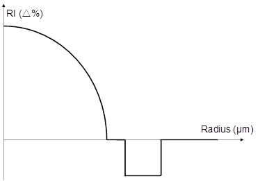
Quasi-single mode transmission is able to inject most of the energy into the base mode of the multi-mode fiber and can maintain the quasi-single mode transmission state over longer distances, enabling the multi-mode fiber to achieve the transmission performance of single-mode fiber. The core layer of single-mode universal fiber adopts parabolic refractive index distribution, and benefits from long-flying PCVD(plasma chemical vapor deposition) technology, which can achieve excellent bandwidth performance in the 850nm to 950nm band and meet the bandwidth requirements of OM5. Additionally, it offers the advantages of low cost and low power consumption for short-distance transmission. Furthermore, it adopts bending-resistant structure design and has excellent bending insensitivity performance.
In addition, the most distinctive feature of this fiber is the reduction in the core layer diameter, along with an optimized core packaging structure design to match the mode field diameter of the fundamental mode with that of standard single-mode fiber in single-mode transmission systems. This enables quasi-basic mode transmission, ensuring minimal interference from multipath crosstalk on the signal during coupling, which can achieve higher speed and longer distance transmission.
Figure 1 Schematic diagram of the profile of single-mode multi-mode universal fiber
Fiber performance
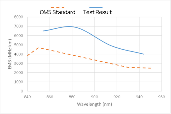
Figure 2 Bandwidth of single and multi-mode universal fiber
The bandwidth of single-mode universal fiber in the wavelength range of 850 to 950nm meets the standard requirements of OM5, supports wavelength division multiplexing technology, and can perform high-speed transmission of 100G b/s and above. The mode field diameter of the base mode at 1310nm is about 10.3 um, which is similar to that of single-mode fiber, and it can support single-mode transmission from 1270nm to 1330nm at 100G and above.
Transmission experiments
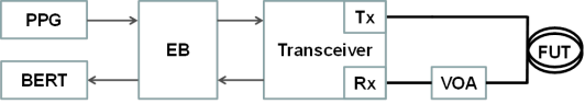
The transmission performance of single-mode and multi-mode general-purpose fibers was tested using commercially available multi-mode and single-mode optical modules. A pulse pattern generator (PPG) generates 215-1 pseudo-random binary sequences (PRBS) at a rate of 25.78 Gb/s and modulates the optical module with an evaluation board (EB). Variable optical attenuation (VOA) is used to modulate the transceiver The received optical power of the transceiver is regulated using variable optical attenuation (VOA), and the output electrical signal is detected by a bit error meter (BERT).
Figure 3 Schematic diagram of the transmission experiment
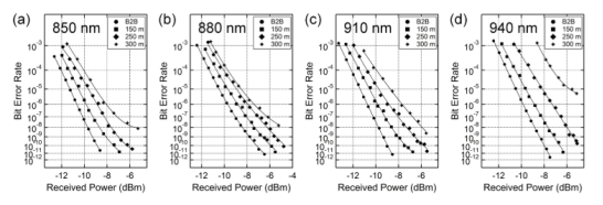
Finisar’s 100G SWDM4 multi-mode optical module was used to test the multi-mode transmission performance of the fiber, and the BER(Bit Error Rate) curves are shown in Figure 4. For the four wavelengths of short wavelength division multiplexing, the BER of 300m link transmission is lower than the FEC(forward error correction) limit (5 & times; 10-5) recommended by the IEEE 802.3 standard, indicating that a single multi-mode universal fiber can transmit 300m in the band of 850nm to 950nm.
Figure 4 BER curves for multi-mode transmission (a) 850 nm, (b) 880 nm, (c) 910 nm and (d) 940 nm
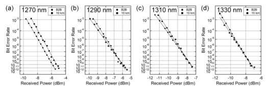
A commercial 100G CWDM4 single-mode optical module was used to test the single-mode transmission performance of the fiber, and the BER curve is shown in Figure 5. Within the operating wavelength range of 1270 to 1330nm, the single-mode universal fiber can achieve 10 km of error-free (10-12) single-mode transmission.
Figure 5 BER curves for single-mode transmission (a) 1270 nm, (b) 1290 nm, (c) 1310 nm and (d) 1330 nm
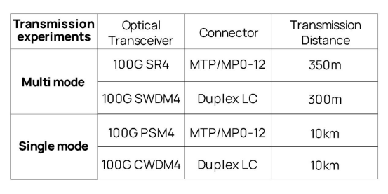
The test results of single-wavelength SR4 and PSM4 are not described here. Combining the advantages of single-mode fiber and multi-mode fiber, the error-free transmission distance of this fiber is shown in the table below.
Figure 6 BER-free transmission distance of single and multi-mode universal fiber
Application Prospects
Multi-mode transmission system has low cost but a shorter transmission distance, while the single-mode transmission system has a longer transmission distance but higher cost, both have their own advantages and disadvantages. In the current situation, it is reasonable to use multi-mode fiber and inexpensive VCSEL light source for short-distance network construction, but if the network requires further speed upgrades to the 1310nm wavelength, it would be necessary to transform into single-mode transmission system and relay single-mode fiber optic cables or lay single-mode and multi-mode fiber hybrid cables. This would greatly increase the investment cost, and the integration of single-mode fiber would be also increase the costs of management and maintenance.
Single and multi-mode universal fiber is compatible with both multi-mode fiber and single-mode fiber, which is excellent in single-mode transmission as well as multi-mode transmission, making them suitable for various application scenarios in Data Centers. This practical transmission solution can meet the upgrade requirements of data center transmissions and reduce the cost of network operation and future bandwidth upgrades.