Passive WDM technology and its application in 4G/5G forward transmission
June 9, 2023
1、Brief description of passive wavelength division forward transmission scheme
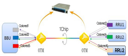
Passive WDM uses WDM technology to combine the circuits from BBU/DU to different RRU/AAU using different wavelengths into a single fiber for transmission. For example, a macro station has 3 RRUs in a certain band of S111 stations and 6 transceiver ports from BBU to RRU, a 6-way OTM (optical terminal multiplexer) on each side of BBU and RRU can combine the transceiver signals between BBU and RRU into a single fiber, as shown in Figure 1.
Figure 1 Passive WDM forwarding scheme
Since OTM is a passive device, each service port’s optical module needs to use different wavelengths which are referred to as color optical modules. The passive WDM system consists of two parts: OTM and color optical modules. When using the system, the optical modules of standard wavelengths (commonly used 1550nm or 1310nm) of BBU/DU or RRU/AAU (commonly known as gray light module or white light module) need to be replaced with color optical modules of the same rate.
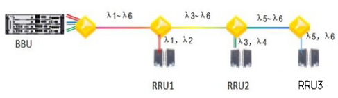
The networking structure supported by passive WDM is divided into double-star type (see Figure 1) and bus type (see Figure 2). The double-star type network structure is mainly used for wireless front transmission, while the bus type is mainly used for coverage in scenarios such as highways, high-speed railways, and tunnels.
Figure 2 Bus-type networking structure of passive WDM
The services supported by the system are mainly related to optical modules, taking 10Gbps color optical modules as an example, the supported services include Base station Pre-transmission services (Option 1 to 7), Ethernet services (GE/10GE) and SDH services (STM-4/16/64).
2、System model and wavelength assignment
When the system is used to carry the wireless forward transmission service, it mainly adopts 6-in-1 (i.e. 1 fiber transmits 6 wavelengths), 12-in-1 and 18-in-1 models; when used for other business purposes, an 8-in-1 model will also be used.
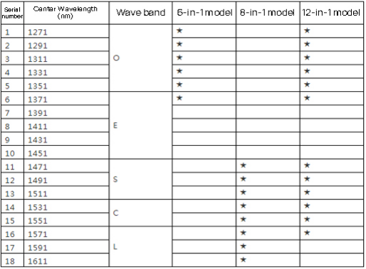
Since CWDM supports a maximum of 18 wavelengths, the system supports a maximum of 18-in-1 model, and models exceeding 18-in-1 need to use DWDM. The wavelengths used in common models are shown in Table 1.
Table 1 Wavelength assignment of common models for passive wavelength division
Although all the wavelengths in the table can be used (non-G.652D fiber should avoid 1371, 1391nm and 1411nm wavelengths), for ease of management, it is recommended that the choice of wavelengths should be uniform.
3, the system’s optical power budget index requirements
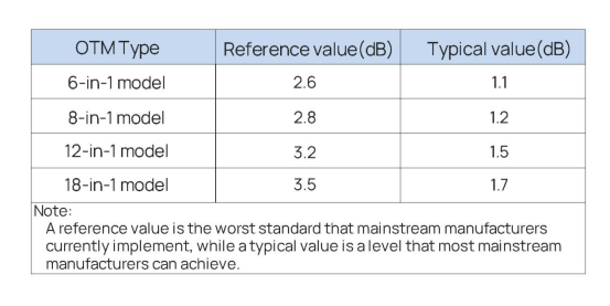
Since the fiber optic network between BBU/DU and RRU/AAU is generally a complex structured ODN (Optical Distribution Network), the optical power budget of BBU/DU and RRU/AAU is taken into consideration in addition to the optical cable length. The insertion loss of the optical cable, the OTM and the number of live connectors in the optical link are also considered.
Table 2 OTM insertion loss reference table
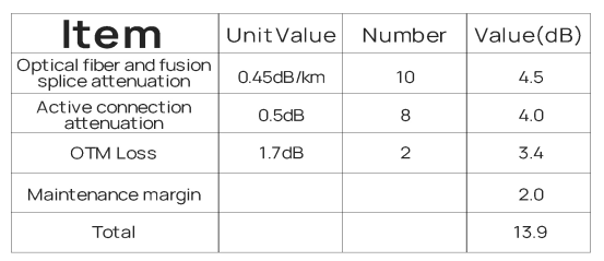
Usually, the optical fiber link length between BBU/DU and RRU/AAU in urban area is generally not more than 10.0km, and the number of live connectors in the link is about 8. Therefore, the optical power budget of the system needs to meet the requirements specified in Table 3.
Table 3 Optical power budget of the system
If there is significant deviation in the fiber link length, the number of active connectors, or the OTM insertion loss from Table 3, it should be recalculated.