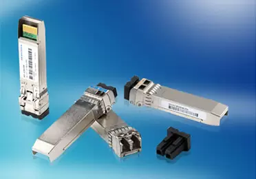
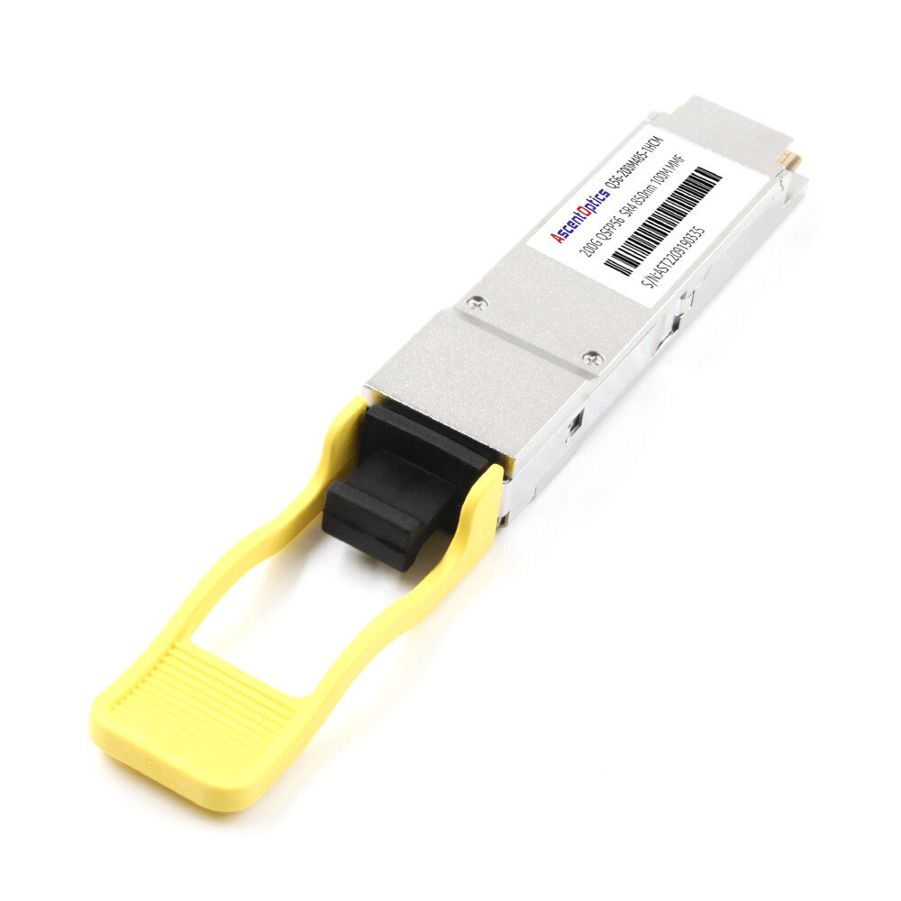
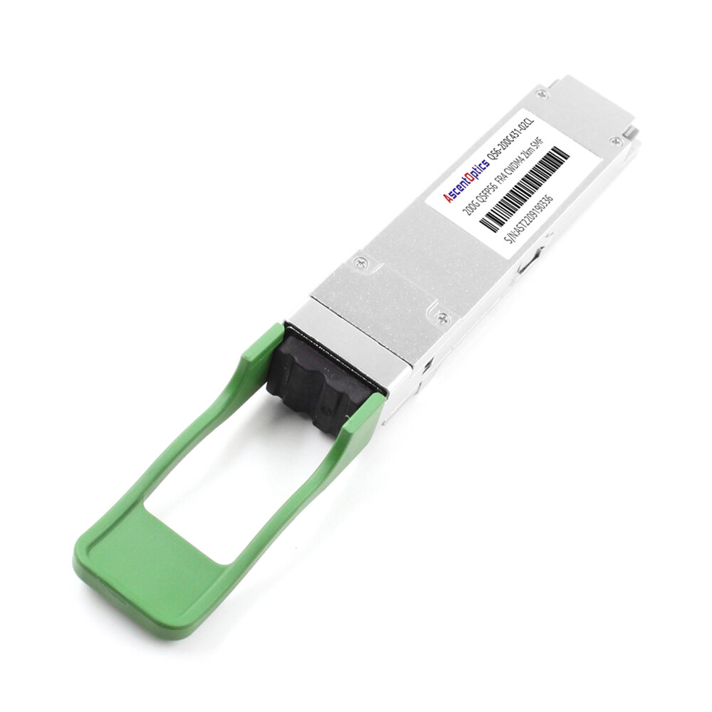
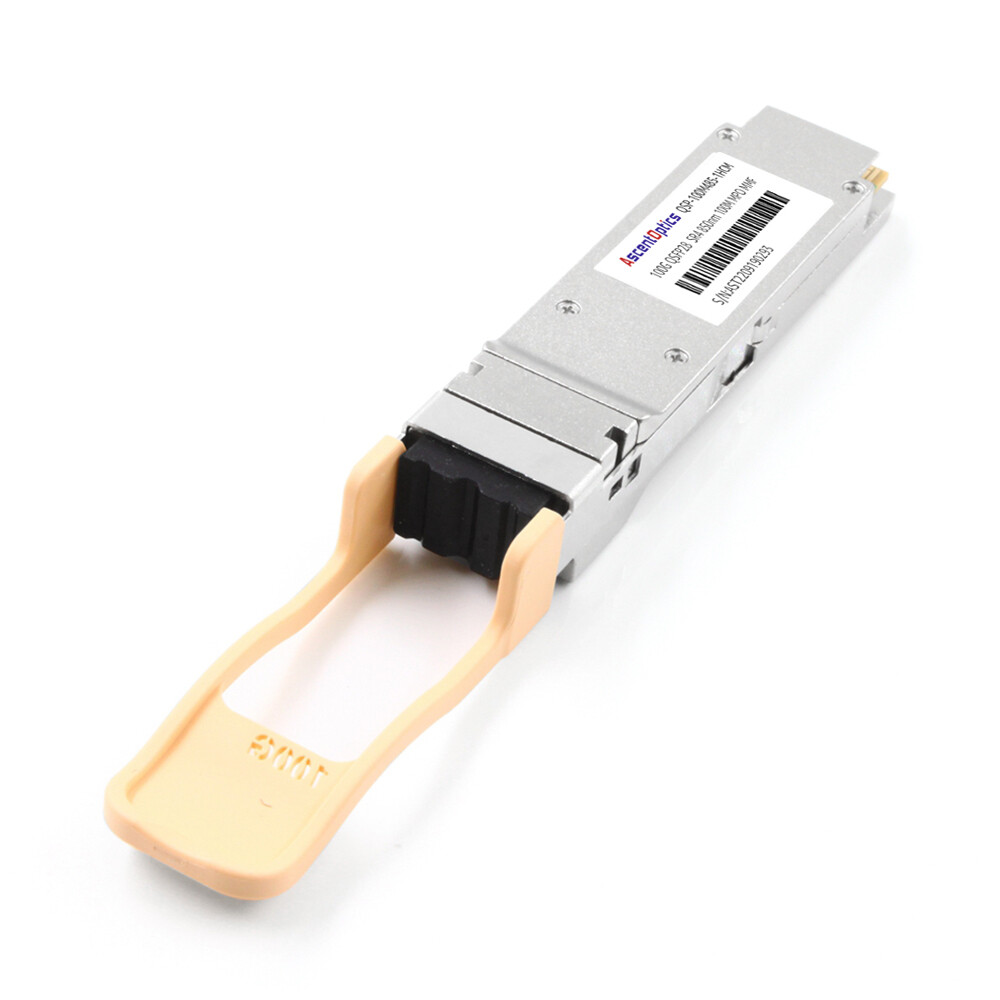
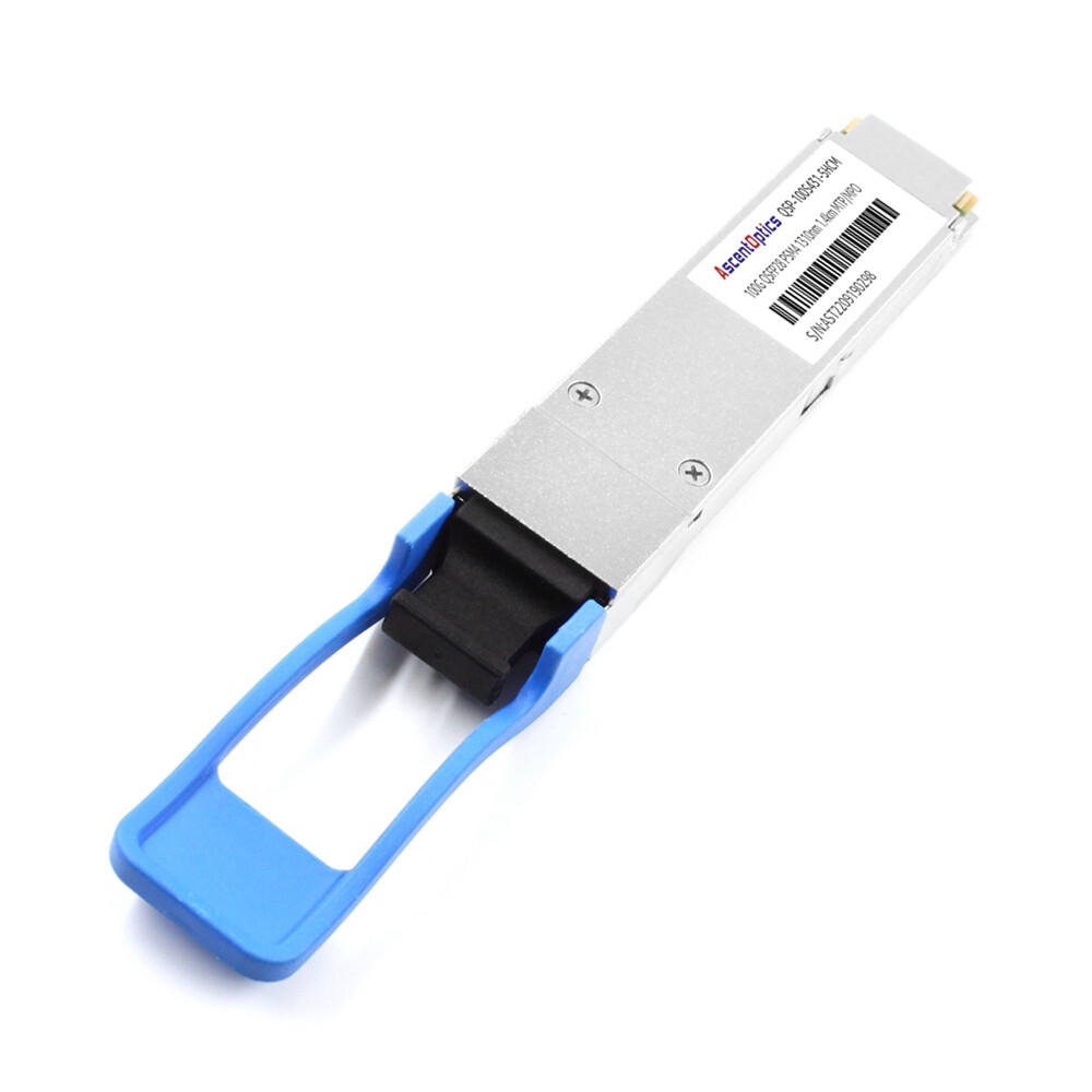
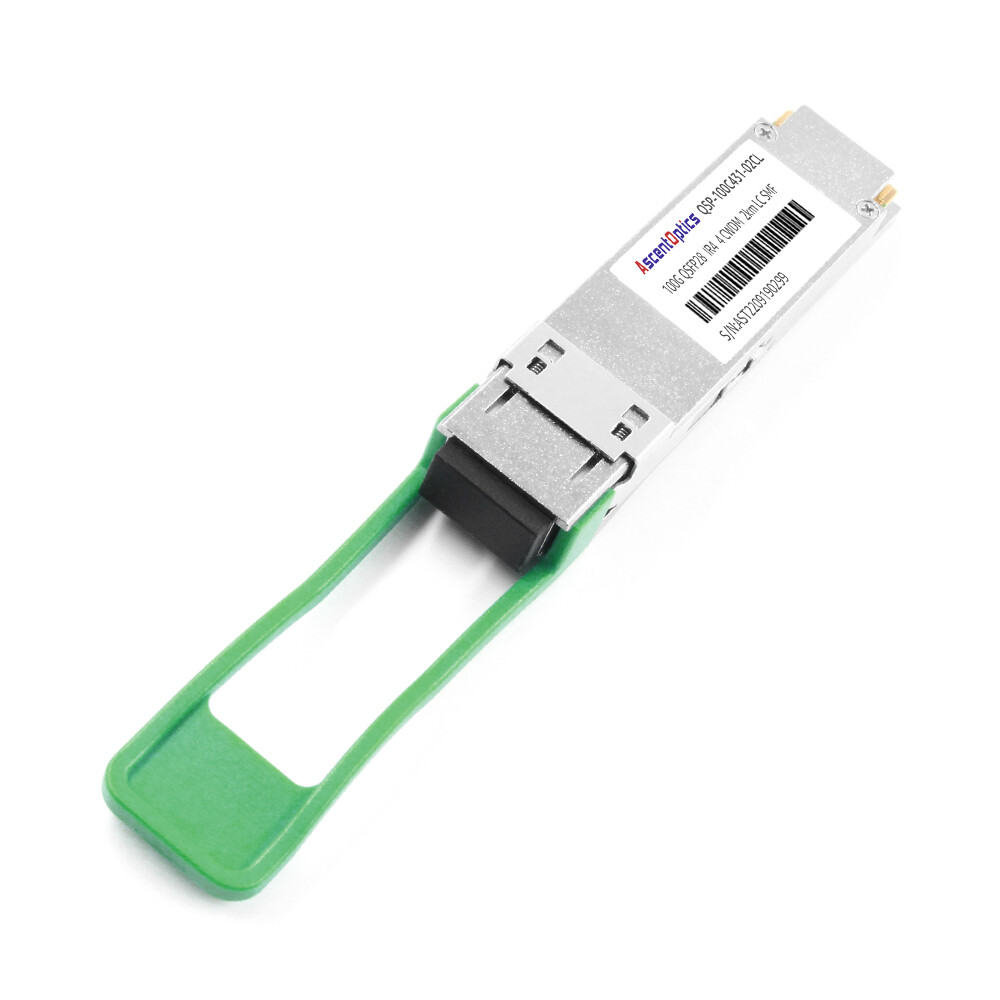
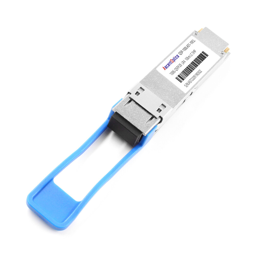
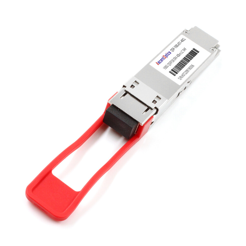
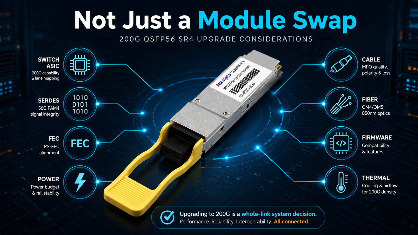
As the demand for data center bandwidth surges, the selection of optical modules has become a critical factor in network upgrades. QSFP28 and QSFP56 modules cater to 100G and 200G Ethernet applications, respectively. Many network teams assume that upgrading from QSFP28 to QSFP56 is as simple as replacing a 100G transceiver with a 200G transceiver. In reality, the module is only one part of the link. The host SerDes, port mode, FEC configuration, cable assembly, fiber type, thermal budget, and firmware support all determine whether a 200G QSFP56 link can come up successfully.
This guide explains how to evaluate a QSFP28 vs QSFP56 upgrade from an engineering and deployment perspective. Instead of only comparing specifications, it focuses on what must be checked before purchasing, installing, and operating 200G QSFP56 transceivers in an existing or new network.
Why a QSFP28 to QSFP56 Upgrade Is Not Just a Module Swap
A common mistake is assuming that a QSFP56 module can replace a QSFP28 module because the two look almost identical. Mechanically, that may be true in many cases. Electrically, it is not.
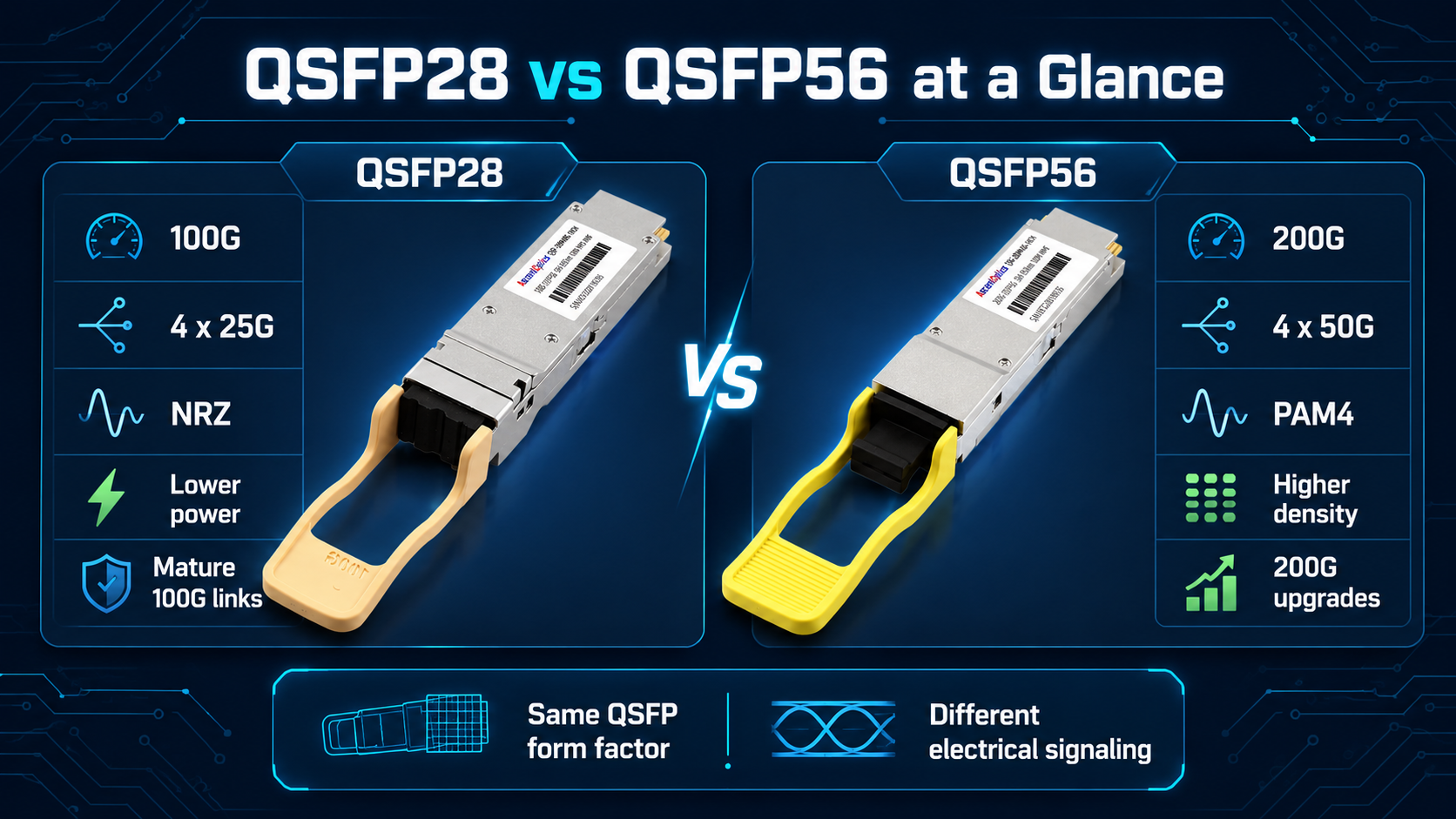
QSFP28 was designed for 100G Ethernet using four 25G lanes. QSFP56 doubles the aggregate bandwidth to 200G by using four 50G-class PAM4 lanes. This requires the host port to support PAM4 signaling, appropriate FEC, higher-speed SerDes, and the correct port mode.
If any part of the link does not support 200G operation, the QSFP56 module may be detected incorrectly, show an unsupported-module warning, or fail to establish link.
For this reason, engineers should treat QSFP56 as a platform-level upgrade rather than a standalone optical module upgrade.
| Item |
QSFP28 |
QSFP56 |
| Main Ethernet speed |
100G |
200G |
| Electrical lane structure |
4 × 25G NRZ |
4 × 50G-class PAM4 |
| Modulation |
NRZ, 1 bit per symbol |
PAM4, 2 bits per symbol |
| Typical optical types |
SR4, LR4, ER4, CWDM4, PSM4 |
SR4, FR4 |
| Common connectors |
MPO/MTP or duplex LC |
MPO/MTP or duplex LC |
| Typical use |
100G leaf-spine, 25G breakout, DCI |
200G spine, AI/HPC fabrics, high-density aggregation |
| Main deployment concern |
Compatibility and reach selection |
PAM4, FEC, power, host support, thermal design |
The important point is that QSFP28 and QSFP56 share a similar physical form factor, but they do not share the same electrical requirements. A QSFP56 module cannot operate in a QSFP28-only port unless the host port itself supports 50G PAM4 signaling, which QSFP28-only ports do not.
For existing 100G networks, a mature QSFP28 transceiver remains a cost-effective choice.
What Changes When Moving from QSFP28 to QSFP56
Before upgrading from QSFP28 to QSFP56, check how each part of the link changes.
| Upgrade Area |
What Changes |
Engineering Recommendation |
| Host port |
100G NRZ changes to 200G PAM4 |
Confirm the port supports 200G QSFP56 mode |
| SerDes |
25G NRZ changes to 50G PAM4 |
Check the switch ASIC and port specification |
| FEC |
PAM4 requires stronger error correction |
Verify RS-FEC or required FEC mode on both ends |
| DAC/AOC |
QSFP28 cables are usually not rated for native 200G |
Use QSFP56-rated DAC or AOC for 200G links |
| Fiber |
Existing fiber may or may not be reusable |
Check connector, fiber type, distance, and link budget |
| Power |
QSFP56 usually consumes more power |
Confirm per-port power limit and airflow design |
| Firmware |
200G modules are more dependent on host recognition |
Check vendor transceiver matrix and software version |
| Breakout |
4×25G and 4×50G breakout are different |
Confirm supported breakout modes before deployment |
This matrix is often more useful than a simple speed comparison because it shows why a 200G link may fail even when the module is physically installed correctly.
Port Compatibility Checklist Before Buying QSFP56
The first step in a QSFP28 to QSFP56 upgrade is checking the host platform. A module cannot create 200G capability if the switch or NIC port does not support it.
Use the following checklist before purchasing QSFP56 optics or cables:
- 1. Does the switch or NIC port support 200G QSFP56 operation?
- 2. Does the host ASIC support 50G PAM4 SerDes?
- 3. Does the port support 200GAUI-4 or another required 200G electrical interface?
- 4. Can the port be configured for 200G mode?
- 5. Does the platform support the required FEC mode?
- 6. Is the transceiver model listed in the vendor compatibility matrix?
- 7. Does the firmware version support the module type?
- 8. Does the port support the power class of the selected QSFP56 module?
- 9. Does the port support the intended breakout mode, such as 4×50G?
- 10. Are both ends of the link using compatible speed, FEC, and optical types?
If the answer to any of these questions is unclear, verify the switch datasheet, transceiver support matrix, and firmware release notes before deployment.
Can QSFP28 Work in a QSFP56 Port?
In many cases, yes, but only if the host port supports fallback to 100G operation.
A QSFP56-capable port may support QSFP28 modules by configuring the electrical lanes to 25G NRZ and operating the port at 100G. This is useful during phased upgrades because a network team can deploy 200G-capable switches first while continuing to use existing 100G QSFP28 optics.
However, this depends on the switch ASIC, firmware, operating system, and vendor configuration. Some platforms support this mode smoothly, while others require manual port configuration or may limit the supported transceiver models.
Do not assume that every QSFP56 port automatically accepts every QSFP28 module. Always verify the port mode and compatibility matrix.
Can QSFP56 Work in a QSFP28 Port?
No. A QSFP28-only port is designed for 25G NRZ lanes and does not have the 50G PAM4 SerDes required for native QSFP56 operation.
A QSFP56 module may physically fit into a QSFP28 cage, but the link will not initialize because the host cannot interpret the PAM4 electrical signal. In some cases, the switch may report an unsupported transceiver. In other cases, the module may be detected but remain link down.
This is one of the most important compatibility rules:
A QSFP28 module may work in a QSFP56-capable port at 100G if the host supports fallback. A QSFP56 module will not work in a QSFP28-only port.
DAC and AOC Compatibility
QSFP28 DACs and AOCs are designed for 100G operation, typically using four 25G NRZ lanes. QSFP56 DACs and AOCs are designed for 200G operation, typically using four 50G-class PAM4 lanes.
For native 200G links, use QSFP56-rated DACs or AOCs. A QSFP28 DAC or AOC should not be assumed to work at 200G, even if it physically fits.
Some switches may allow a QSFP56-capable port to operate at 100G using a QSFP28 DAC or AOC. In that case, the link is not running as a native 200G QSFP56 link. It is operating in a fallback or down-speed mode, and support depends on the host platform.
For short-reach 200G links, a 200G QSFP56 DAC cable is usually the most cost-effective option. When longer reach or better cable management is required, a 200G QSFP56 AOC can be a better choice.
FEC and PAM4 Link Issues
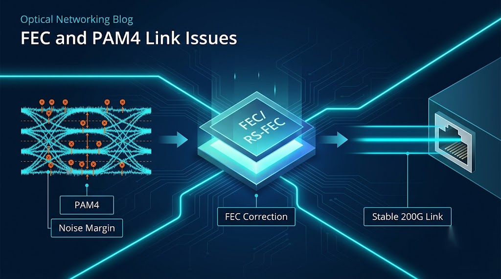
PAM4 is the key technology that allows QSFP56 to double the bandwidth of QSFP28 without increasing the lane count. Instead of using two voltage levels like NRZ, PAM4 uses four voltage levels to encode two bits per symbol.
The benefit is higher data throughput. The trade-off is reduced signal margin. PAM4 links are more sensitive to noise, loss, jitter, crosstalk, dirty connectors, and marginal cabling.
That is why FEC is critical in QSFP56 deployments.
For 200G links, the host platform and link partner must support the correct FEC mode. If FEC is disabled, mismatched, or unsupported, the link may fail even when the optics and fiber are correct.
Common FEC-related problems include:
- •One end has RS-FEC enabled while the other end does not
- •The switch uses a different FEC mode from the link partner
- •Auto-negotiation does not select the expected FEC setting
- •The module requires host FEC but the platform configuration is incorrect
- •The port is forced to an incompatible speed or breakout mode
For stable 200G operation, configure FEC according to the switch vendor’s guide and verify that both ends of the link use matching settings.
Why a QSFP56 Module May Not Link Up
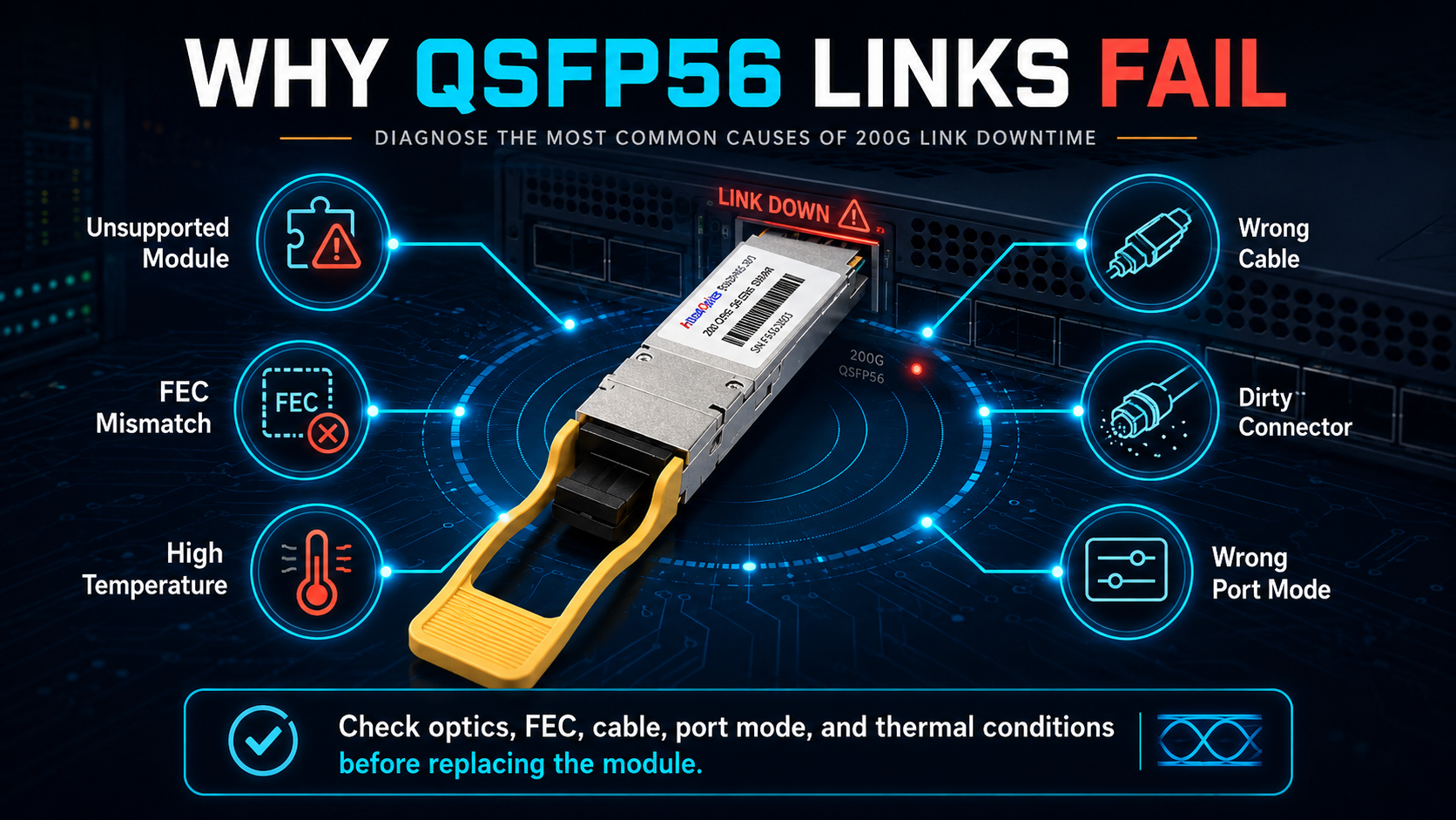
When a QSFP56 module fails to establish link, the cause is not always the optical module itself. In many cases, the issue is related to host compatibility, port configuration, or link settings.
| Symptom |
Possible Cause |
Recommended Check |
| Module is not detected |
Unsupported coding or incompatible firmware |
Check transceiver matrix and firmware version |
| Module is detected but link is down |
Port not set to 200G mode |
Verify port speed configuration |
| Link flaps or shows errors |
FEC mismatch or poor signal integrity |
Check FEC mode, fiber cleanliness, and cable quality |
| High error counters |
Dirty connectors or excessive insertion loss |
Inspect and clean connectors, test optical power |
| 200G DAC does not work |
Cable not rated or not supported by host |
Use approved QSFP56 DAC |
| Module temperature is high |
Power or airflow issue |
Check thermal class, airflow direction, and fan speed |
| Breakout does not work |
Unsupported breakout mode |
Confirm 4×50G or other breakout support |
| QSFP56 fails in QSFP28 port |
Host lacks 50G PAM4 SerDes |
Use a QSFP56-capable port |
A structured troubleshooting process can prevent unnecessary module returns. Always check host capability and configuration before assuming the transceiver is defective.
Breakout Planning
QSFP28 is commonly used for 4×25G breakout to SFP28 ports when the switch and cable support breakout mode. This is useful for connecting 100G switch ports to multiple 25G server-facing links.
QSFP56 breakout is different. A native 200G QSFP56 port typically uses four 50G PAM4 lanes, so the common breakout direction is 4×50G, depending on platform support and cable type.
Do not assume that a QSFP56 port can automatically support every breakout option. The supported breakout modes depend on the switch ASIC, operating system, port group design, and cable assembly.
Before designing breakout links, confirm:
- •Whether the port supports breakout
- •Whether the breakout mode is 4×50G, 2×100G, or another mode
- •Whether the cable assembly is supported
- •Whether FEC settings are required per breakout lane
- •Whether the destination ports support the same speed and FEC mode
Breakout is a host-side feature, not only a transceiver feature.
Power and Thermal Planning
QSFP56 modules usually consume more power than QSFP28 modules because they operate at higher lane speeds and often require more advanced DSP and signal processing.
Typical QSFP28 modules may draw around 3.5 W to 5.5 W, depending on optical type and reach. Typical QSFP56 modules may draw around 4.5 W to 7.5 W or more, depending on design, distance, and vendor specification.
In a 32-port switch, optics-only heat can become significant:
- •32 QSFP28 modules at 3.5 W to 5.5 W = about 112 W to 176 W
- •32 QSFP56 modules at 4.5 W to 7.5 W = about 144 W to 240 W
This does not include switch ASIC, fan, power supply, or other system power. In high-density 1RU switches, the thermal impact of optics can affect airflow, fan speed, acoustic levels, and rack-level power planning.
Before deploying QSFP56 at scale, check:
- •Per-port optical power limit
- •Maximum module power class supported by the switch
- •Front-to-back or back-to-front airflow direction
- •Rack power capacity
- •Cooling capacity
- •Cable management impact on airflow
- •Ambient temperature around the switch faceplate
Underestimating optics heat is one of the most common mistakes in 100G to 200G migration projects.
Deployment Scenarios
The right choice depends on network traffic, existing hardware, budget, and upgrade timeline.
| Scenario |
Recommended Path |
Reason |
| Existing 100G network still has enough capacity |
Stay on QSFP28 |
Lower cost, mature compatibility, simpler operation |
| Spine layer is congested but leaf layer remains 100G |
Upgrade spine to QSFP56 |
Increases backbone capacity without replacing every leaf switch |
| AI/ML or HPC cluster needs higher east-west bandwidth |
Move to QSFP56 or higher |
200G links reduce oversubscription and improve fabric capacity |
| Servers still use 25G ports |
Use QSFP28 with 4×25G breakout |
Economical and widely supported |
| Server-facing links need 50G |
Use QSFP56 with 4×50G breakout |
Requires host and cable support |
| New greenfield data center expects 400G soon |
Consider QSFP-DD or OSFP |
Avoids a short intermediate 200G lifecycle |
| Existing fiber plant is mostly LC SMF |
Consider 200G FR4/LR4 |
May reuse duplex single-mode fiber |
| Existing fiber plant is MPO MMF |
Consider 200G SR4 |
Check OM3/OM4 distance and loss budget |
QSFP56 is often a strong middle-tier upgrade for organizations that have outgrown 100G but are not ready for full 400G deployment. However, for greenfield builds with fast traffic growth, a 400G-capable platform may provide a better long-term path.
If you are evaluating whether 200G is the right next step, read our complete 200G Guide for Data Center Networks.
100G to 200G to 400G Migration Roadmap
A successful migration is usually phased. Instead of replacing the entire network at once, many teams upgrade the highest-pressure layers first.
Phase 1: Stabilize the 100G QSFP28 Fabric
Before moving to 200G, make sure the current 100G network is stable.
Recommended actions:
- •Audit existing QSFP28 optics and cables
- •Identify oversubscribed spine or aggregation links
- •Check error counters and optical power levels
- •Replace aging or unstable modules
- •Standardize transceiver coding and spare parts
- •Document current fiber types, connectors, and link distances
This phase helps avoid carrying existing link problems into the 200G upgrade.
Phase 2: Upgrade Spine or Aggregation to 200G QSFP56
The spine or aggregation layer is often the first place to deploy QSFP56 because it carries large volumes of east-west traffic.
Recommended actions:
- •Deploy QSFP56-capable switches in the spine layer
- •Use 200G SR4, DR4, FR4, or LR4 based on distance and fiber type
- •Verify FEC mode before production cutover
- •Confirm the transceiver compatibility matrix
- •Check port power limits and airflow direction
- •Test links with real traffic before full rollout
This approach increases network capacity without forcing an immediate replacement of all leaf switches.
Phase 3: Prepare for 400G QSFP-DD or OSFP
QSFP56 can serve as a practical step between 100G and 400G, but it should be planned with the next generation in mind.
Recommended actions:
- •Choose new platforms with clear 400G upgrade paths where possible
- •Plan fiber infrastructure for future 400G optics
- •Avoid locking the network into unsupported breakout modes
- •Leave rack power and cooling headroom
- •Standardize cabling routes for higher-density patching
- •Evaluate whether future links will use DR4, FR4, LR4, or breakout optics
A good 200G deployment should make a future 400G migration easier, not harder.
Conclusion
The difference between QSFP28 and QSFP56 is more than 100G versus 200G. QSFP28 is a mature, reliable, and cost-effective solution for 100G networks. QSFP56 doubles the bandwidth in the same QSFP form factor, but it requires PAM4-capable host ports, correct FEC configuration, compatible cables, sufficient power, and proper thermal planning.
If your existing 100G network still has enough capacity, QSFP28 remains a practical choice. If your spine layer, AI cluster, or aggregation network needs higher throughput, QSFP56 can provide a balanced upgrade path to 200G. For new deployments with near-term 400G requirements, QSFP-DD or OSFP platforms may be worth considering from the beginning.
The best approach is to evaluate QSFP28 vs QSFP56 as a complete link and platform decision. Check the host port, SerDes, FEC, optics, cable, fiber, power, and migration roadmap before buying modules. That is the safest way to avoid compatibility problems and build a scalable path from 100G to 200G and beyond.
Need help verifying QSFP56 compatibility with your switch platform? Contact us for QSFP56 compatibility support.
Frequently Asked Questions
What is the difference between QSFP56 and QSFP28?
QSFP28 delivers 100 Gbps using four 25 Gbps NRZ lanes. QSFP56 delivers 200 Gbps using four ~50 Gbps PAM4 lanes. Both share the same form factor, but QSFP56 requires PAM4-capable host ports and stronger FEC.
Is QSFP56 backward compatible with QSFP28?
Partially. A QSFP28 module can often operate in a QSFP56-capable port at 100G, but a QSFP56 module cannot operate in a QSFP28-only port.
What is QSFP56 used for?
QSFP56 is used for 200G Ethernet links in data center spine layers, AI/ML cluster fabrics, HPC interconnects, 5G midhaul aggregation, and high-density enterprise networks.
How fast is QSFP56?
QSFP56 supports an aggregate data rate of 200 Gbps.
Is QSFP56 the same as QSFP-DD?
No. QSFP56 is a 200G standard QSFP module. QSFP-DD (Double Density) is a deeper module with an extra row of electrical contacts, designed for 400G and 800G.
What cables work with QSFP28 and QSFP56?
Each generation requires matched DAC or AOC cables. QSFP28 cables use NRZ signaling; QSFP56 cables use PAM4 signaling. Breakout cables are also generation-specific.
Post Views: 1,341