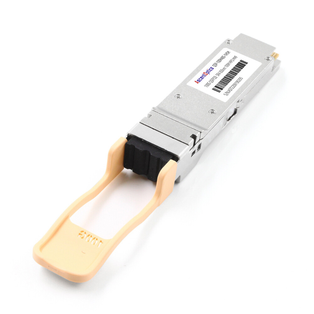
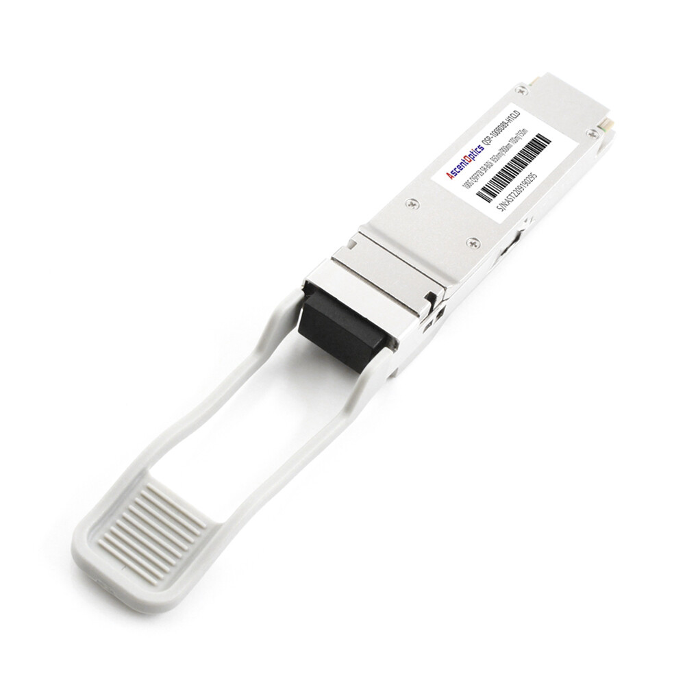
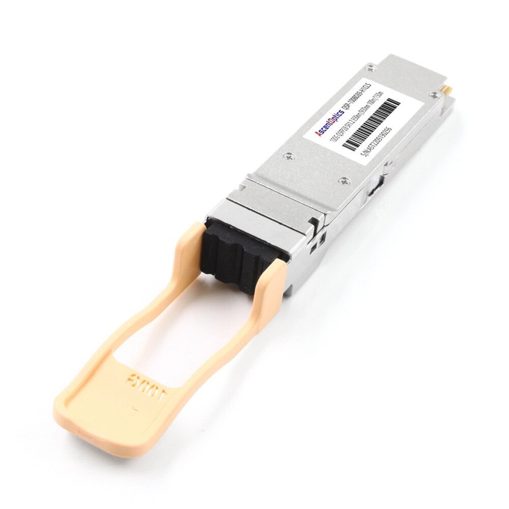
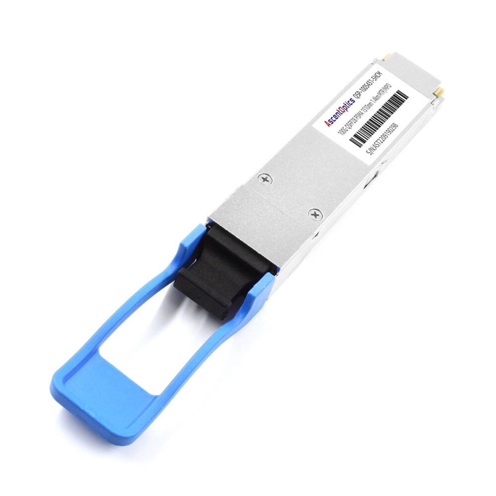
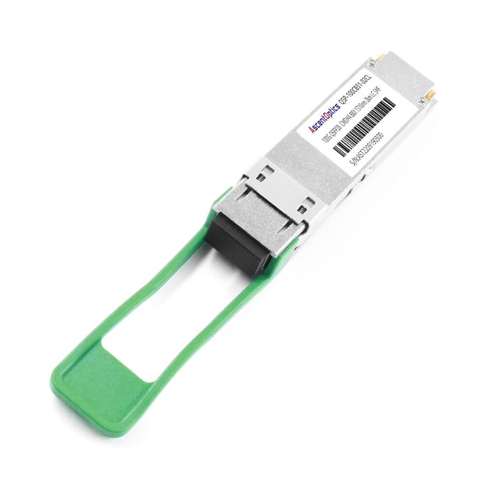
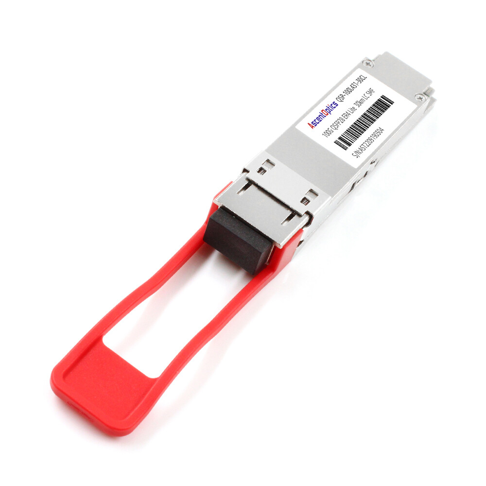
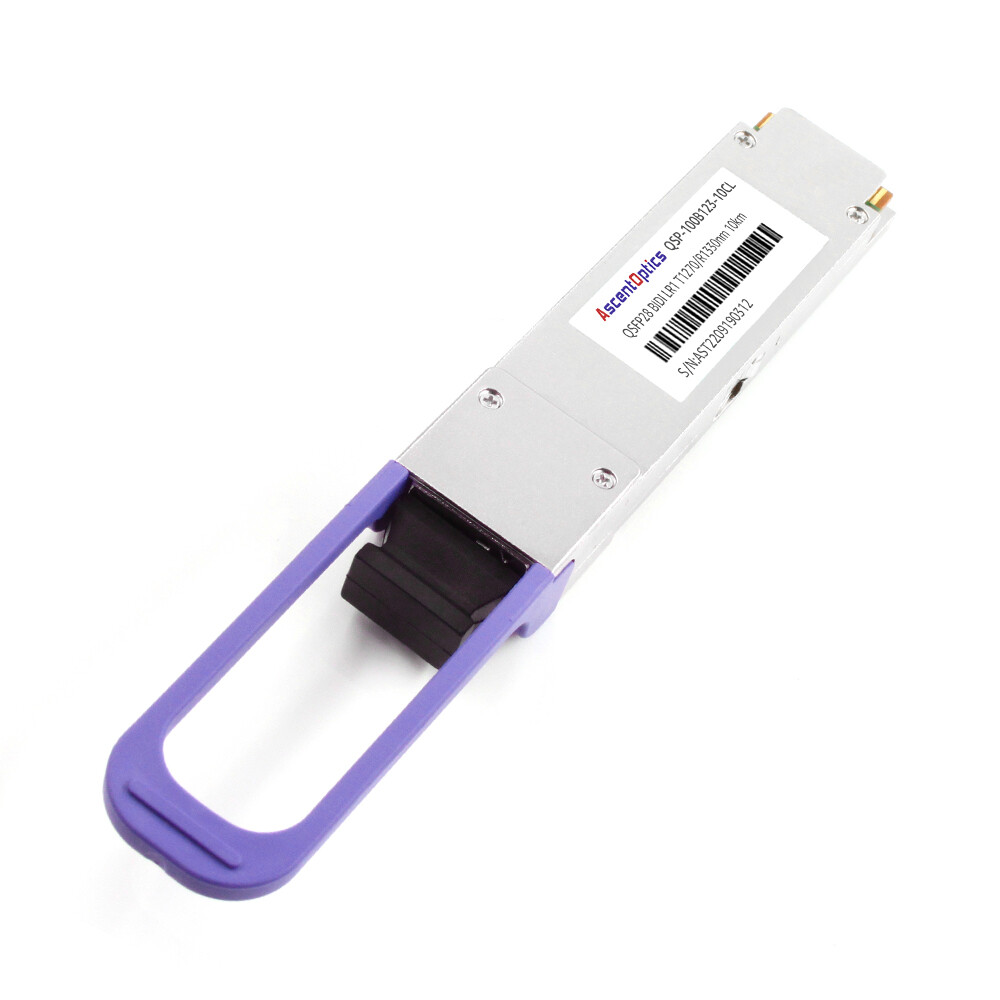
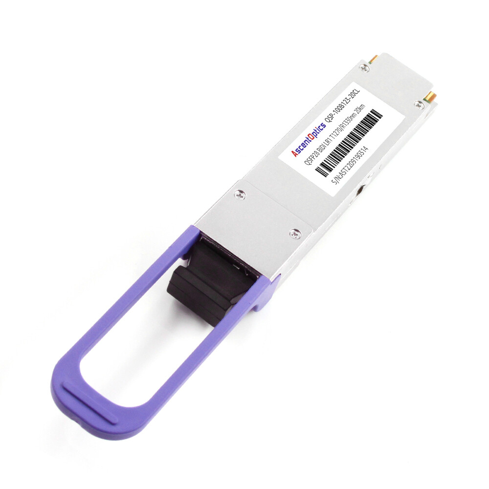
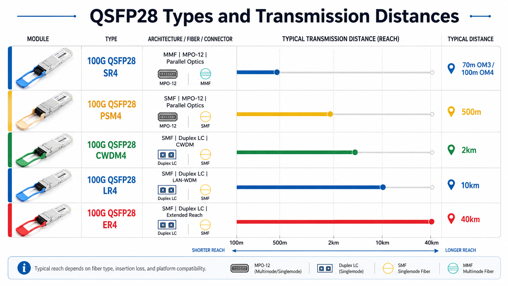
100G QSFP28 optical transceiver modules provide compact, hot-pluggable connectivity for 100 Gigabit Ethernet in data centers, enterprise networks, telecom infrastructure, and high-performance computing environments. The QSFP28 form factor normally presents four 25 Gb/s electrical lanes to the host. Depending on the optical standard, the module may transmit four parallel optical lanes, combine four wavelengths onto duplex fiber, or convert the host signal into a single 100G PAM4 optical wavelength.
Selecting the right module requires more than matching “100G” on both ends. Engineers must verify the optical standard, connector, fiber type, reach, FEC requirement, port mode, power class, temperature rating, and exact switch or router compatibility. This guide explains those factors and corrects several common misconceptions about 100G QSFP28 optics.
What Is a 100G QSFP28 Optical Transceiver?
QSFP28 stands for Quad Small Form-factor Pluggable 28. The “quad” refers to four high-speed electrical lanes, and “28” reflects the approximately 25 to 28 Gb/s signaling capability of each lane. Four lanes combine to carry a 100 Gigabit Ethernet signal while retaining the compact footprint of the earlier QSFP+ form factor.
A QSFP28 module is not a single universal optical design. The same mechanical form factor can support very different physical media specifications, including short-reach multimode optics, parallel single-mode optics, wavelength-multiplexed optics, single-lambda PAM4 optics, bidirectional optics, and specialized coherent DWDM modules.
Core characteristics
- •Host interface: typically four 25 Gb/s NRZ electrical lanes for conventional 100G QSFP28 ports.
- •Data rate: 100 Gigabit Ethernet; some platforms also support breakout into four 25GbE channels when the module or cable and port are designed for breakout.
- •Fiber media: multimode fiber (MMF) or single-mode fiber (SMF), depending on the optical standard.
- •Connector: MPO/MTP for parallel optics or duplex LC for wavelength-multiplexed, single-lambda, and many bidirectional optics.
- •Power consumption: model-dependent rather than a fixed QSFP28 value; common standard optics are often in the 2.5W to 5.5W range, while coherent QSFP28 optics can be higher.
- •Management: most modules support digital optical monitoring (DOM/DDM) for temperature, voltage, laser bias current, transmit power, and receive power.
Technical clarification
A QSFP28 module is usually a four-lane device on the host side. In single-lambda 100G DR, FR, LR, or ER-Lite modules, internal electronics convert the four host lanes into one 100G PAM4 optical wavelength. Therefore, “single-lambda” describes the optical interface, not necessarily a single electrical lane at the switch ASIC.
Major 100G QSFP28 Types and Transmission Distances
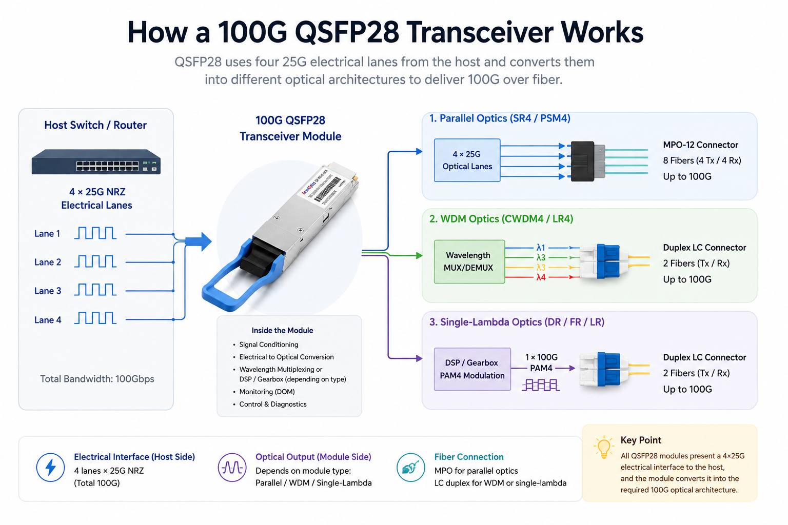
The correct transceiver is determined primarily by distance, fiber infrastructure, connector type, and interoperability requirements. Typical reach values are listed below; actual deployment limits depend on the applicable standard, link loss budget, patch panels, connector loss, fiber quality, and vendor implementation.
100GBASE-SR4: Uses four parallel 850 nm optical lanes over multimode fiber. It normally uses an MPO-12 connector and supports up to 70 m over OM3 or 100 m over OM4. SR4 is widely used for short data center links and can support 4 × 25GbE breakout with the correct cabling and platform configuration.
100G PSM4: Uses four parallel optical lanes over single-mode fiber and normally uses an MPO-12 connector. Typical reach is up to 500 m. PSM4 is an MSA-based specification rather than an IEEE 100GBASE designation.
100GBASE-DR: Uses one 100G PAM4 wavelength over duplex single-mode fiber with duplex LC connectors. The IEEE-defined reach is 500 m. DR is useful for leaf-spine links and for migration between 100G and 400G DR4-based architectures.
100G CWDM4: Combines four 25G NRZ wavelengths in the 1271 to 1331 nm range onto duplex single-mode fiber. It uses duplex LC connectors and typically supports 2 km. CWDM4 is an MSA specification commonly used for data center interconnects.
100G-FR: Uses one 100G PAM4 wavelength over duplex single-mode fiber with duplex LC connectors. Typical reach is 2 km under the 100G Lambda MSA specification.
100GBASE-LR4: Uses four LAN-WDM wavelengths around 1310 nm over duplex single-mode fiber with duplex LC connectors. It supports up to 10 km and remains a widely deployed standards-based option for campus, aggregation, and data center interconnect links.
100G-LR single-lambda: Uses one 100G PAM4 wavelength over duplex single-mode fiber, typically with duplex LC connectors, for reaches up to 10 km under relevant MSA specifications. FEC and interoperability requirements must be checked carefully.
100G ER4 / ER4-Lite: Uses duplex single-mode fiber and duplex LC connectors for extended reach. Depending on the module and host FEC support, practical reach may be 30 km or 40 km. Engineers should confirm the exact optical budget and whether host-based FEC is mandatory.
100G ZR4 or coherent QSFP28: Specialized long-reach modules may support approximately 80 km without amplification, while coherent QSFP28 DCO variants can support longer amplified DWDM links. These modules have higher power, thermal, management, and platform requirements than standard client optics.
Explore our QSFP28 Module Types Selection Guide for 100G Networks→
Connector, Fiber, Wavelength, and Modulation
The original article treated duplex LC, 1310/1550 nm wavelengths, and sub-3.5W power as general QSFP28 characteristics. In practice, these values are specific to individual optical variants.
MPO/MTP parallel optics
SR4 and PSM4 use separate transmit and receive fibers for each optical lane. A common implementation uses an MPO-12 interface with eight active fibers. Polarity, fiber type, connector cleanliness, and the mapping between lanes must be correct. An MPO link cannot be replaced with a duplex LC patch cord without an appropriate conversion architecture.
Duplex LC optics
CWDM4, FR, LR4, single-lambda LR, ER4, and many BiDi designs use duplex LC connectors over two-fiber single-mode links. The module either multiplexes multiple wavelengths internally or transmits one high-speed PAM4 wavelength.
Wavelength and modulation
- •SR4: four 850 nm NRZ lanes over MMF.
- •PSM4: four parallel lanes near 1310 nm over SMF.
- •CWDM4: four CWDM wavelengths, commonly 1271, 1291, 1311, and 1331 nm.
- •LR4/ER4: four LAN-WDM wavelengths around 1295 to 1309 nm.
- •DR/FR/LR single-lambda: one 100G PAM4 wavelength near 1310 nm.
- •Coherent ZR: tunable C-band wavelength with coherent modulation and DSP.
QSFP28 Compared with QSFP+, SFP+, and CFP
Form-factor comparisons should separate physical size from supported data rate and host capability.
SFP+: A compact single-lane form factor commonly used for 10GbE. Some proprietary long-reach SFP+ modules extend far beyond standard short-reach applications, so SFP+ should not be described simply as a “low-end” or short-distance technology.
QSFP+: Uses the same general front-panel footprint as QSFP28 but is primarily associated with 40GbE using four 10 Gb/s lanes. A 100G QSFP28 module does not operate in a 40G-only QSFP+ port merely because the mechanical size is similar.
QSFP28: Provides 100GbE in a compact, high-density format using four 25 Gb/s host lanes. Many modern QSFP28 ports can also support QSFP+ modules or breakout modes, but this depends on the exact switch hardware and software.
CFP/CFP2: Earlier 100G form factors with a larger footprint and generally higher power envelope. They remain relevant in some transport and coherent optical applications but offer lower faceplate density than QSFP28.
Cisco, Arista, and Juniper Compatibility
MSA compliance defines mechanical dimensions, electrical interfaces, management memory maps, thermal expectations, and related form-factor requirements. It improves interoperability, but it does not guarantee that every QSFP28 module will be accepted by every switch or router.
For Cisco-compatible QSFP28 transceivers, the module must be correctly programmed and validated for the exact Cisco platform and operating system release. The same principle applies to Arista, Juniper, and other vendors. Platform compatibility matrices remain the most reliable source for approved combinations.
Compatibility checklist
- •Exact switch, router, NIC, or line-card model and software version.
- •Port capability: 100G mode, supported breakout mode, and supported transceiver power class.
- •Required FEC mode, including RS-FEC, FC-FEC, or no FEC, as specified by the interface.
- •Optical standard and lane architecture at both ends of the link.
- •Connector type, fiber type, polarity, and link-loss budget.
- •Module EEPROM coding, vendor identification, and alarm thresholds.
- •Commercial or industrial operating-temperature requirement.
- •Vendor support policy for third-party optics.
Important compatibility point
Two modules can share the same connector and nominal reach yet still fail to link if their optical standards, FEC behavior, lane mapping, or host port configuration differ. Always match the complete interface specification, not only the speed and connector.
100G DAC and AOC Options
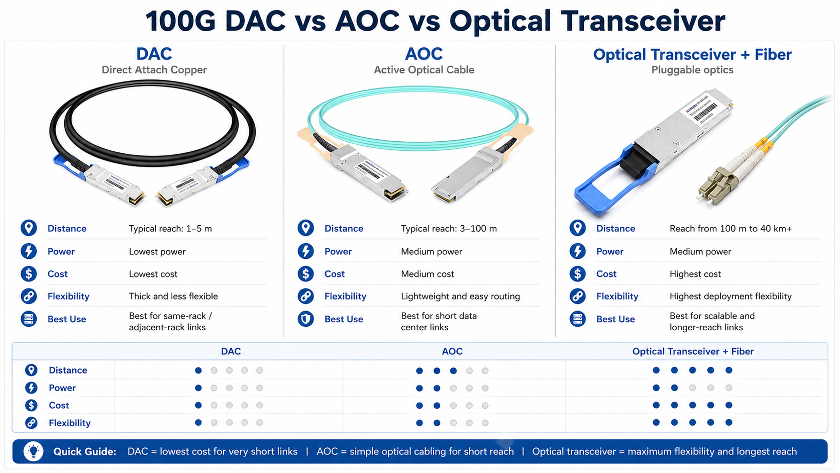
For short connections, integrated cable assemblies may be more practical than separate optical modules and patch cords.
Direct attach copper (DAC)
- •Best suited to short in-rack or adjacent-rack connections, commonly around 1 to 5 m depending on cable type and platform.
- •Passive DAC uses almost no module power and offers low cost and low latency.
- •Active copper cable can extend reach but consumes power and must be specifically supported by the host.
- •Copper assemblies are thicker and less flexible than AOCs, which can complicate dense cable management.
Active optical cable (AOC)
- •Uses permanently attached optical engines and fiber, typically for several meters to approximately 100 m; longer versions are vendor-specific.
- •Lighter and easier to route than copper at longer distances.
- •Immune to electromagnetic interference and well suited to high-density data center cabling.
- •Costs more and consumes more power than passive DAC, and a failed endpoint normally requires replacement of the complete cable assembly.
Installation and Troubleshooting Considerations
Many 100G deployment failures are caused by configuration or cabling rather than a defective optical module. A structured commissioning process reduces troubleshooting time.
- 1. Confirm that both ports are configured for the same speed, lane mode, and FEC setting.
- 2. Verify that the transceiver standard is identical or explicitly interoperable at both ends.
- 3. Inspect and clean LC or MPO connectors before insertion. MPO contamination can affect individual lanes and cause high bit-error rates even when the link comes up.
- 4. For SR4 and PSM4, validate MPO polarity and lane mapping. For breakout links, verify that each transmit lane reaches the correct receive lane.
- 5. Check DOM readings for temperature, voltage, transmit power, receive power, and laser bias current. Compare values with warning and alarm thresholds.
- 6. Calculate the optical link budget, including fiber attenuation, connector loss, splice loss, patch-panel loss, and engineering margin.
- 7. Review switch logs for unsupported-transceiver messages, FEC mismatch, high BER, local fault, remote fault, or lane alignment errors.
- 8. Test with a known-good module and known-good fiber to isolate the fault domain.
Single-Lambda 100G and the Migration Beyond 100G
Traditional 100G SR4, PSM4, CWDM4, and LR4 implementations use four optical lanes or wavelengths. Single-lambda 100G optics such as DR, FR, and LR use PAM4 to carry 100 Gb/s on one optical wavelength. The QSFP28 module generally contains the gearbox, DSP, and FEC functions needed to convert the host’s four 25G electrical lanes into the single-lambda optical signal.
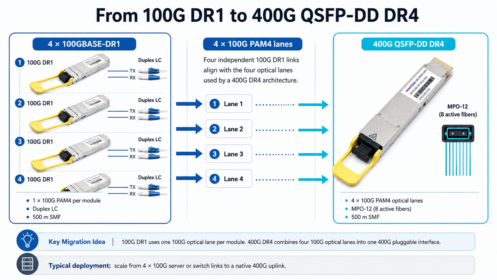
Single-lambda 100G improves the migration path to 400G because a 400GBASE-DR4 interface can be viewed as four parallel 100GBASE-DR optical lanes. This enables 400G-to-4 × 100G optical breakout architectures when the host port, transceiver, and fiber cabling support the required lane mapping.
Higher-speed networks increasingly use QSFP-DD and OSFP form factors for 400G and 800G. IEEE is also developing 1.6 Tb/s Ethernet specifications under the P802.3dj project. Network planners should separate finalized standards from draft or vendor-specific implementations when describing future 1.6T products.
How to Select the Right 100G QSFP28 Module
- 1. Define the application: server access, leaf-spine, campus, data center interconnect, metro, telecom, or coherent transport.
- 2. Measure the actual path length and estimate total optical loss rather than selecting only by nominal distance.
- 3. Identify the installed fiber: OM3/OM4/OM5 multimode or OS2 single-mode, plus connector type and polarity.
- 4. Choose the optical architecture: parallel MPO, duplex LC WDM, single-lambda PAM4, BiDi, or coherent DWDM.
- 5. Verify platform support, port mode, FEC, software release, and power budget.
- 6. Confirm operating temperature, DOM support, and any requirement for industrial-grade optics.
- 7. Evaluate total lifecycle cost, including patch panels, fiber count, cleaning, spares, and migration to 400G or 800G.
- 8. Request platform-specific test evidence from the compatible-optics supplier and validate a sample in the target hardware before volume deployment.
Conclusion
100G QSFP28 remains one of the most versatile optical form factors for high-density Ethernet networks. However, successful deployment depends on selecting the correct optical standard rather than relying on generic QSFP28 specifications. Connector type, fiber, wavelength, modulation, reach, FEC, power, temperature, and platform coding must all be verified as a complete system.
For Cisco-compatible QSFP28 transceivers, a reliable supplier should provide exact platform coding, compatibility verification, optical performance data, and pre-shipment testing. These controls reduce link failures and make third-party 100G optics a practical option for data center, enterprise, and service-provider networks.
Frequently Asked Questions (FAQs)
A: What is a 100G QSFP28 Optical Transceiver Module?
In high-speed networking equipment, a 100G QSFP28 optical transceiver module is created to provide a data transmission speed of 100G over fiber optic cables. These modules come in various types to fit different network requirements, such as Cisco-compatible QSFP-100G-SR4-S and others. They have a networking device connecting port supported with the QSFP28 interface.
Q: How does the QSFP28 100G module support 100m transmission distances?
The QSFP28 100G module is designed for short-range communications, especially models like Cisco QSFP-100G-SR4-S supporting up to 100m when used with duplex LC multimode fiber which makes it perfect choice for intra-building or data center connections.
Q: Are Cisco compatible QSFP28 transceivers compliant with industry standards?
Yes they are compliant with multiple industry standards such as SFP-DD MSA which ensures interoperability and reliability in wide range of network environments. This compliance allows them to be easily integrated into existing networks without need for additional configurations.
Q: Which forms of media can 100G QSFP28 optical modules be connected with?
A: The single-mode fiber (SMF optical transceiver module) is used for longer distances while multimode fiber is used for shorter distances as well as a variety of other media. Some models, such as the bidi (Bi-Directional) or the QSFP28 single lambda, allow different ways of connecting, which means they can work with many network architectures.
Q: Can Cisco QSFP28 modules support transmissions beyond 100m?
A: Yes, there are Cisco QSFP28 modules that are designed to transmit over longer distances. For example, the Cisco QSFP-100G-PSM4-S and Cisco QSFP-100G-DR-S can reach up to 2km and 500m, respectively, on single-mode fiber. These are great for inter-building connections within campus networks or across larger data centers.
Q: What does a 28G data rate mean in QSFP28 modules?
A: The “28” in 28G data rate in QSFP28 modules refers to the per-channel transmission rate where each channel supports nearly 28 Gigabits per second (Gbps). Since these modules make use of four channels this gives them a total speed of slightly above ,100G which enhances capacity and efficiency for data centers and network backbones.
Q: Are there high-density QSFP28 100G optical modules available?
A: Yes, there are high density QSFP28 100G optical modules such as the Cisco QSFP-100G-CWDM4-S which are designed for dense network environments. These employ Wavelength Division Multiplexing (WDM) technologies that enable higher data rates over a single fiber optic cable thereby reducing complexity and cost associated with cables.
Q: What is the difference between SFP28 and QSFP28 in terms of application?
A: SFP28 has lower data rates (25G) which makes it suitable for less bandwidth-intensive applications while QSFP28 is designed for higher speed networks (100G) that require more capacity and density. In addition to this, QSFP28 modules can support breakout configurations which allow them to connect with four 25G SFP28 modules so as to distribute traffic hence providing flexibility in network design.
Post Views: 5,397