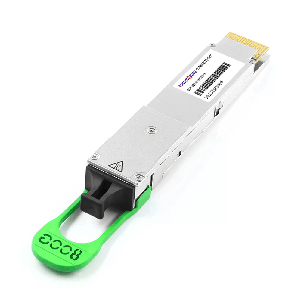
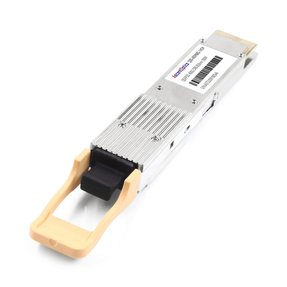
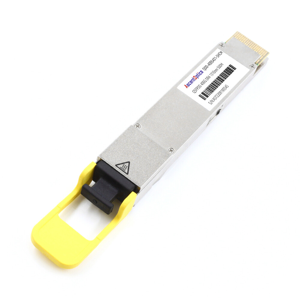
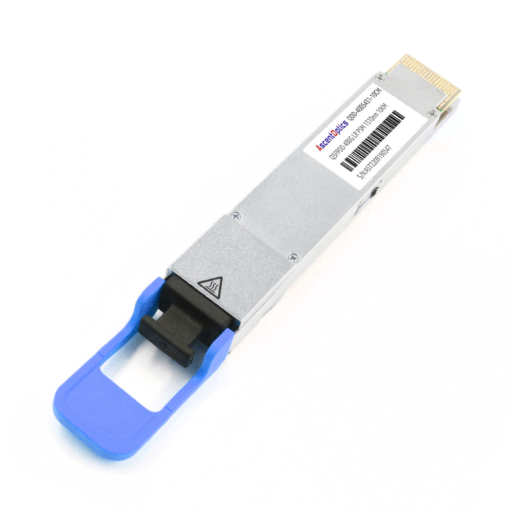
In 400G/800G optical modules, PAM4 utilizes four distinct voltage levels to carry twice the amount of information, making the eye diagram a primary tool for evaluating signal integrity. By analyzing parameters such as eye height, eye width, level separation, and noise/jitter, one can assess link margin and the risk of bit errors, providing an intuitive basis for the debugging and acceptance testing of high-speed optical interconnects.
What Is PAM4 and Why Does It Have Three Eyes?
PAM4 stands for four-level pulse amplitude modulation. Where NRZ (non-return-to-zero) uses two voltage levels to carry one bit per symbol, PAM4 uses four levels to carry two bits per symbol. The four levels are typically mapped to the pairs 00, 01, 11, and 10 using Gray coding, so a single level error usually flips only one bit instead of two.
This is the trade-off that makes 400G and 800G possible. A 400G link built on NRZ would need a baud rate that most channels and lasers simply cannot deliver. PAM4 doubles the data rate at the same baud rate, which is why modern 400G QSFP-DD transceivers and 800G modules are built on it.
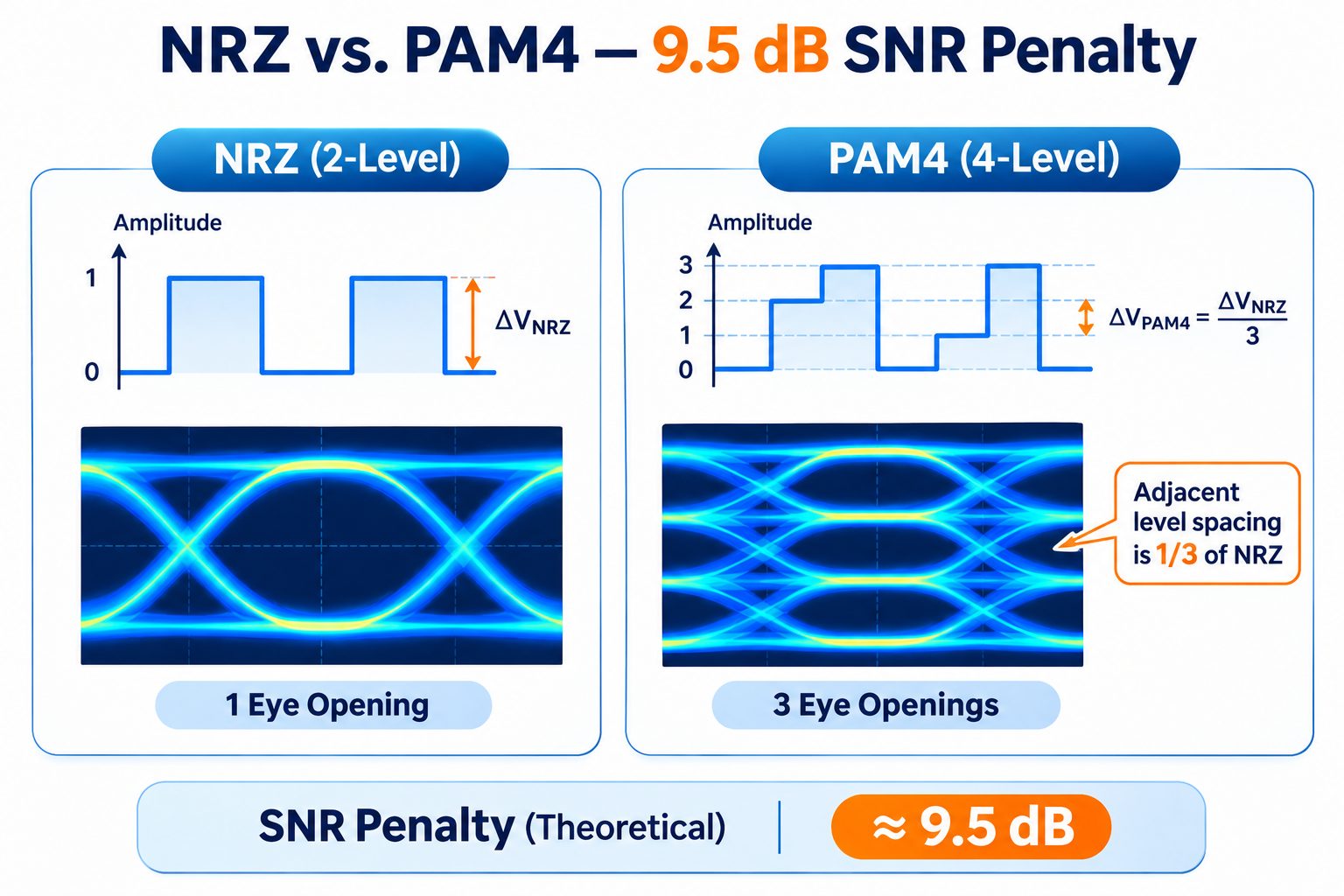
The cost of that trade shows up directly in the eye diagram. An NRZ signal has two levels and one eye opening. A PAM4 signal has four levels and three eye openings, which engineers call the lower, middle, and upper eye. The receiver places three decision thresholds, or slicers, midway between the four levels. These sit at normalized values of -2, 0, and +2 relative to the four signal levels of -3, -1, +1, and +3.
Three eyes sound like more information, and in one sense they are. But each eye is only about one-third the vertical amplitude of an NRZ eye, which is the core reason PAM4 signals are harder to keep clean. Understanding that trade-off is the first step to reading the diagram correctly.
How to Read a PAM4 Eye Diagram
Reading a PAM4 eye diagram means measuring three things at once: how tall each eye is, how wide each eye is, and how evenly the three eyes line up. Most link failures in 400G and 800G systems trace back to one of these three measurements drifting out of spec.
Eye Height and Eye Width
Eye height is the vertical opening between the two signal levels that form an eye. It represents the noise margin. A taller eye means the receiver can tolerate more amplitude noise before it misreads a level.
Eye width is the horizontal opening, measured in time. It represents the timing margin. A wider eye means the receiver can tolerate more jitter and inter-symbol interference before a bit slides into the wrong time slot.
In a healthy PAM4 signal, all three eyes should show similar height and width. When the middle eye looks fine but the outer eyes are compressed, that asymmetry is a clue, not a coincidence. It usually points to transmitter nonlinearity rather than random noise.
Eye Linearity (RLM)
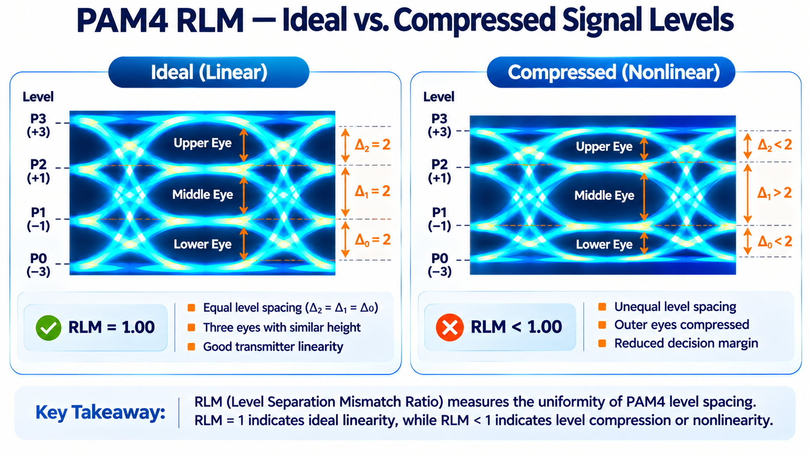
RLM stands for level separation mismatch ratio, and it is the cleanest single number for judging whether the three eyes are evenly spaced. A perfectly linear transmitter produces three eyes of equal height, and RLM equals 1.
When a transmitter compresses its outer levels or drifts in the middle, the three eyes become unequal, and RLM drops below 1. For the same overall signal amplitude and noise level, PAM4 reduces the minimum adjacent-level spacing to one-third of that of NRZ. This corresponds to a theoretical 20log10(3) ≈ 9.54 dB reduction in the level-spacing-to-noise ratio. The actual receiver sensitivity or BER penalty depends on the noise distribution, symbol statistics, equalization, and receiver implementation.
If the levels drift closer together, the receiver’s thresholds no longer sit midway between them, and the effective noise margin shrinks even though the total signal amplitude has not changed.
Inter-Eye Skew and Compression
Beyond height and linearity, engineers also check two subtler distortions. Inter-eye skew is horizontal misalignment, where the three eyes do not reach their widest point at the same instant. Eye compression is vertical, where the outer eyes squeeze toward the middle.
Tektronix groups these as the two main categories of PAM4 nonlinearity in its application note on PAM4 signaling. Both reduce link margin, and both are best caught on a real oscilloscope rather than inferred from a datasheet number.
PAM4 vs NRZ Eye Diagram: The SNR Penalty
For the same overall signal amplitude and noise level, PAM4 reduces the minimum adjacent-level spacing to one-third of that of NRZ. This corresponds to a theoretical 20log10(3) ≈ 9.54 dB reduction in the level-spacing-to-noise ratio. The actual receiver sensitivity or BER penalty depends on the noise distribution, symbol statistics, equalization, and receiver implementation.
High-speed PAM4 Ethernet links typically rely on FEC to achieve the required post-FEC error performance. NRZ links at 25G and 100G could often get by on a clean eye alone. PAM4 links at 400G and 800G expect errors, then correct them in real time using Reed-Solomon FEC.
If you are sizing a deployment rather than debugging one, our guide to 800G optical transceivers walks through how PAM4 and higher baud rates shape real link budgets.
Key PAM4 Eye Metrics in Optical Transceivers
The eye diagram is a picture, but the optical industry measures it with a handful of standardized numbers. When you read a 400G or 800G module datasheet, these are the figures that tell you whether the picture is good.
TDECQ
TDECQ (Transmitter and Dispersion Eye Closure for PAM4) is a standardized optical transmitter quality metric that quantifies the equivalent power penalty caused by transmitter impairments and chromatic dispersion. It is measured using a defined reference receiver and equalization procedure. Lower TDECQ generally indicates better transmitter signal quality, but compliance must be evaluated against the applicable IEEE 802.3 optical interface specification.
TDECQ limits vary by IEEE 802.3 optical PMD and must be checked against the applicable standard. A lower measured TDECQ generally indicates a smaller transmitter-related power penalty. However, link reliability also depends on OMAouter, receiver sensitivity, channel loss, dispersion, and FEC margin. TDECQ should therefore be evaluated alongside other optical performance parameters rather than as a standalone indicator of link health.
Extinction Ratio and OMA
For PAM4 optical signals, the outer extinction ratio (ER) is the ratio of the highest optical power level (P3) to the lowest optical power level (P0), typically expressed in decibels. OMAouter is the difference between these two optical power levels, expressed in linear power units or converted to dBm. While ER and OMAouter characterize the optical modulation amplitude, the actual opening of each PAM4 eye also depends on level spacing, noise, jitter, inter-symbol interference, and transmitter linearity.
Both matter because the receiver’s decision thresholds are set against optical power. A module with a weak extinction ratio closes the eye vertically, which is exactly the condition that raises the error floor and eats into FEC margin.
Pre-FEC BER Requirements
Pre-FEC BER requirements depend on the specific optical or electrical interface and its associated FEC scheme. For many IEEE 802.3 PAM4 optical interfaces using KP4 FEC, a pre-FEC BER limit of approximately 2.4 × 10⁻⁴ is commonly referenced. OIF-CEI electrical interfaces use application-specific error performance requirements that vary across reach classes and standard generations. Engineers should verify the applicable BER limits against the relevant interface specification rather than applying a single threshold to all PAM4 links.
These numbers are the reason eye metrics matter. The cleaner the eye, the lower the raw error rate, and the more margin the FEC has left for temperature swings, aging, and patch-panel losses. NIST has published a robust algorithm for PAM4 eye-diagram analysis that formalizes how the four levels and three eye amplitudes are located, which is useful background if you want to understand exactly how these measurements are computed.
Eye Diagram vs. TDECQ vs. BER: Understanding PAM4 Signal Quality
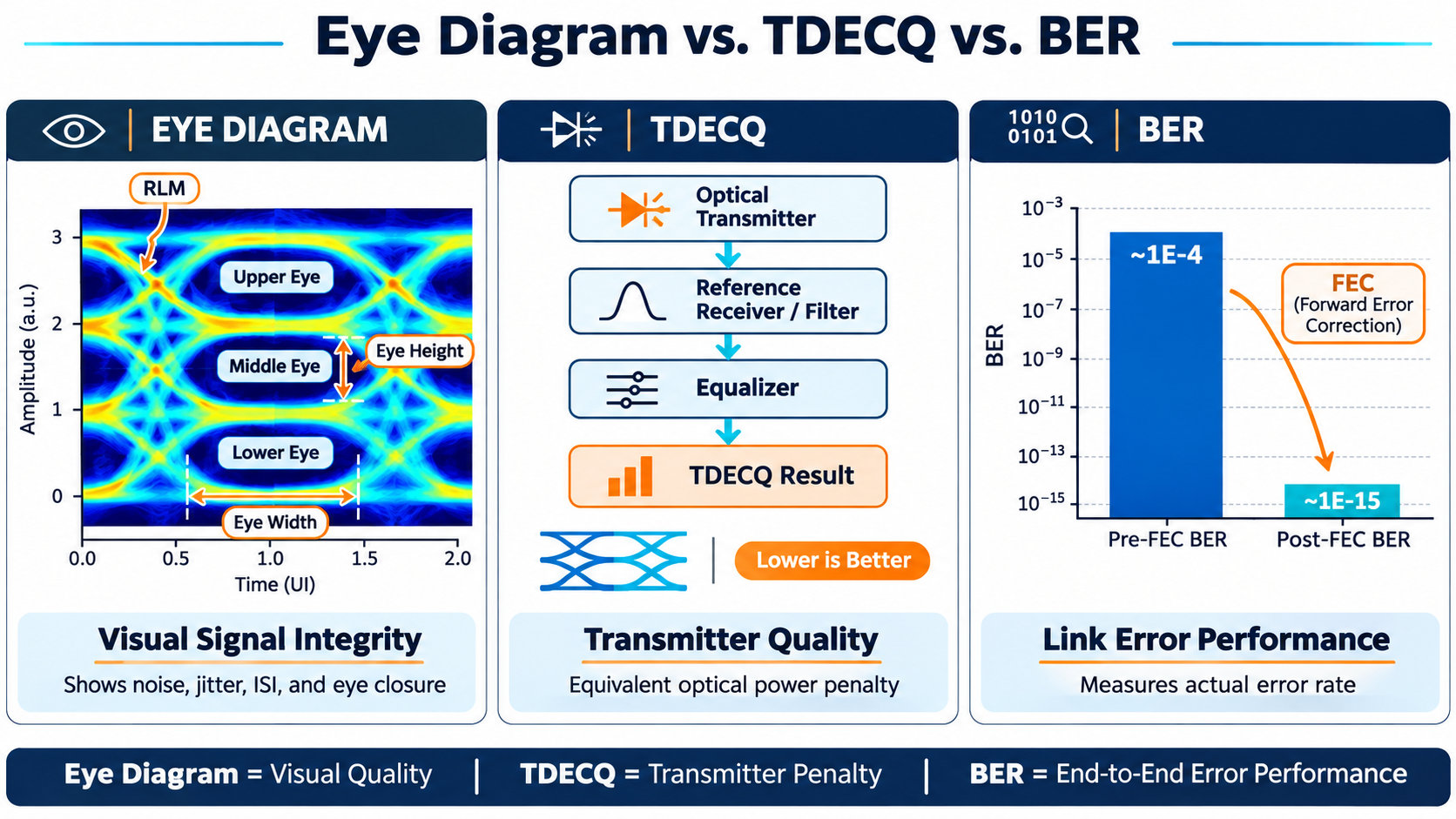
A PAM4 eye diagram provides a visual indication of signal integrity, but an open eye alone does not guarantee reliable transmission. Engineers must also evaluate TDECQ and bit error rate (BER) to assess transmitter quality and overall link performance.
PAM4 Eye Diagram: Visualizing Signal Integrity
A PAM4 eye diagram displays three eye openings corresponding to four amplitude levels. Eye height and width indicate noise and timing margins, while RLM measures the uniformity of level spacing.
A wider, more symmetrical eye generally indicates better signal quality, but visual inspection alone cannot confirm compliance with an optical interface standard.
TDECQ: Evaluating Transmitter Quality
TDECQ (Transmitter and Dispersion Eye Closure for PAM4) quantifies the equivalent optical power penalty associated with transmitter impairments and dispersion under standardized measurement conditions.
Lower TDECQ generally indicates better transmitter performance. However, acceptable limits depend on the applicable IEEE 802.3 optical PMD specification.
BER: Measuring Link Error Performance
BER measures the proportion of incorrectly received bits. In PAM4 links using forward error correction (FEC), two metrics are particularly important:
- Pre-FEC BER: Indicates the error rate before correction and helps assess link quality and FEC margin.
- Post-FEC BER: Indicates the residual error rate after correction and helps verify link reliability.
FEC can significantly reduce errors, but a low post-FEC BER does not necessarily indicate sufficient operating margin.
Key Differences
| Metric |
Primary Purpose |
| Eye Diagram |
Visualizes noise, jitter, ISI, and eye closure |
| RLM |
Evaluates PAM4 level-spacing uniformity |
| TDECQ |
Measures equivalent optical transmitter power penalty |
| Pre-FEC BER |
Assesses raw link errors and FEC margin |
| Post-FEC BER |
Evaluates residual errors after FEC |
Why These Metrics Matter Together
An 800G optical transceiver may exhibit a clean PAM4 eye and acceptable TDECQ while experiencing increased pre-FEC BER due to fiber loss, receiver noise, or temperature variations.
Likewise, a link may maintain a low post-FEC BER even as its FEC correction margin decreases.
For reliable 400G and 800G optical interconnects, eye quality, TDECQ, and BER should be evaluated together rather than independently.
How PAM4 Eye Diagrams Are Measured
Measuring a PAM4 eye diagram is more involved than measuring NRZ. The signals are faster, the eyes are smaller, and the equalization can reshape the eye before you ever see it.
Oscilloscope and Optical-to-Electrical Converter
To capture an optical PAM4 eye, you need a real-time or sampling oscilloscope with enough bandwidth for the baud rate, plus an optical-to-electrical converter to turn the optical signal back into a voltage. For 53 GBaud signals, that converter and scope combination needs to be wide enough to preserve the eye rather than round it off. The IEEE 802.3bs guidance on oscilloscope measurements covers the trade-offs between sampling and real-time capture, including how clock recovery is handled.
Test Patterns
The pattern you send through the link changes what the eye reveals. Short patterns like PRBS13Q stress the equalizer and expose deterministic jitter. Longer patterns like PRBS31Q expose low-frequency effects and baseline wander. SSPRQ, a stress pattern built for PAM4, is designed to find weaknesses that simpler patterns miss. A module that looks perfect under PRBS13Q can still fail under SSPRQ, which is why production validation rarely relies on a single pattern.
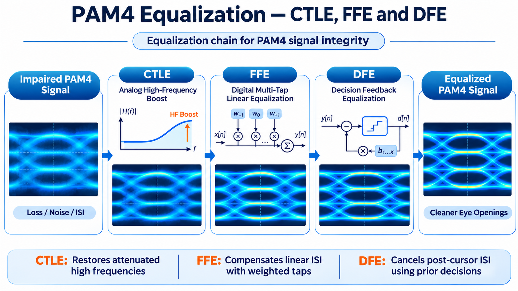
Equalization: CTLE, FFE, and DFE
By the time a PAM4 eye reaches the receiver, the channel has smeared it. Receivers reconstruct the eye using continuous-time linear equalization (CTLE), feed-forward equalization (FFE), and decision feedback equalization (DFE). Each stage reshapes the signal, which means the eye you see on a scope depends heavily on what equalization has been applied. This is one reason two engineers can measure the same link and disagree: they are looking at the eye at different points in the equalization chain.
Equalization also connects directly to the LPO debate. Linear pluggable optics remove the DSP from the module and push equalization onto the host ASIC, which changes how and where the eye is recovered. Our guide to QSFP56 LPO modules explains that architectural shift in more detail.
Why PAM4 Eye Quality Matters for 400G/800G Transceiver Selection
Eye quality also has to survive the form factor and the switch environment. Dense 400G QSFP-DD and 800G OSFP ports run hot and close together, and that stress shows up first as a closing eye. Modules that hold a wide, symmetric PAM4 eye at high temperature are the ones that will keep a production fabric stable, not just pass a bench test at room temperature.
If you are building toward higher density, start with our overview of what QSFP112 is to see how the same PAM4 principles scale into the next generation of 400G modules.
Conclusion
The move to PAM4 rewrote the rules of signal integrity. What was once a single eye became three, and the margin that NRZ gave away freely now has to be earned through careful transmitter design, equalization, and forward error correction.
The key takeaways are straightforward. A PAM4 eye diagram has three stacked eyes, each about one-third the amplitude of an NRZ eye, which is why PAM4 carries a roughly 9.5 dB SNR penalty and depends on FEC. The metrics that matter are eye height, eye width, RLM for linearity, and TDECQ for optical eye closure. And the cleanest test of any 400G or 800G module is whether its PAM4 eye stays open and symmetric across temperature, not just on a cool bench.
Frequently Asked Questions (FAQ)
1. Why does PAM4 have three eye openings?
PAM4 uses four amplitude levels to transmit two bits per symbol, creating three eye openings. Each eye represents the separation between two adjacent signal levels.
2. What is a good PAM4 eye diagram?
A good PAM4 eye diagram has three clear, symmetrical openings with sufficient eye height and width, indicating low noise, jitter, and signal distortion.
3. What is the difference between PAM4 eye height and eye width?
Eye height indicates the vertical noise margin, while eye width represents the timing margin against jitter and inter-symbol interference (ISI).
4. What is an acceptable TDECQ value for 400G and 800G optics?
Lower TDECQ generally indicates better transmitter quality. Acceptable limits vary by optical PMD and must meet the applicable IEEE 802.3 specification.
5. What causes PAM4 eye closure?
Common causes include noise, jitter, bandwidth limitations, inter-symbol interference (ISI), transmitter nonlinearity, and signal attenuation.
6. Can a PAM4 link have a good eye diagram but high BER?
Yes. A clean transmitter eye does not guarantee low end-to-end BER. Receiver noise, channel impairments, and insufficient link margin can still cause errors.
Post Views: 101