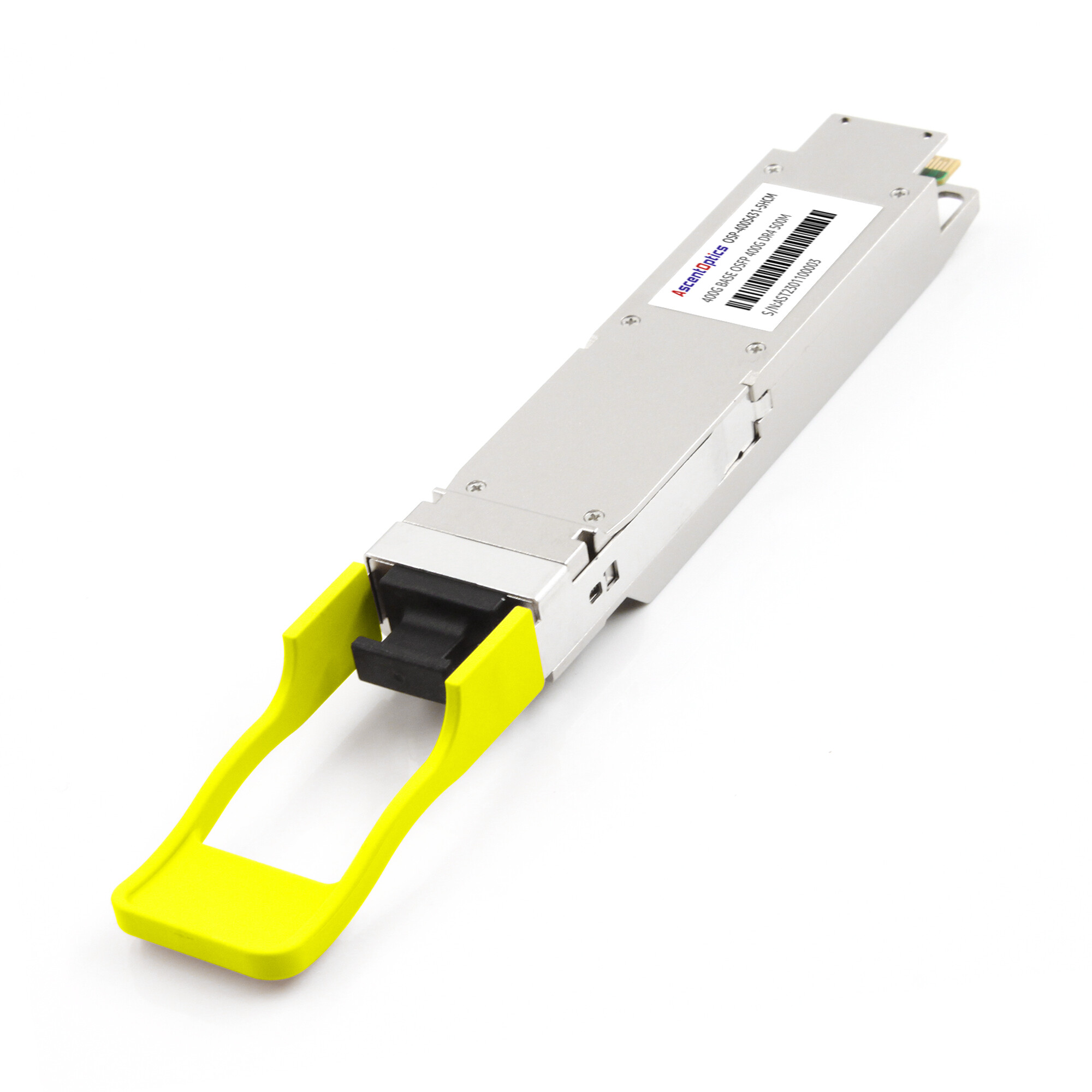
Here’s something that surprises engineers the first time they see it: a 400G module gets its speed not from adding more light lanes, but from squeezing two bits into every symbol. That encoding trick is 400G PAM4, and it’s the single biggest reason a modern data center can move 400 gigabits a second through a QSFP-DD or OSFP port.
If you’ve worked with 100G optics, you know NRZ, the older two-level signaling that carried one bit per symbol. PAM4 changed the game by carrying two. What you might not have internalized is how that choice plays out inside the module: why some 400G transceivers use 4x100G lanes and others 8x50G, and why DR4, FR4, and LR4 reach different distances on the same silicon.
What Is 400G PAM4?
400G PAM4 is a signaling method used in 400G Ethernet optical modules. It encodes two bits into each of four amplitude levels, rather than the one bit of older NRZ, so each optical lane carries twice the data at the same symbol rate.
Here’s the mechanics. NRZ uses two voltage levels, high and low, to represent a 1 or a 0. One bit per symbol. PAM4 uses four levels, which map to the bit pairs 00, 01, 11, and 10. That’s two bits per symbol. At a fixed baud rate, PAM4 therefore moves twice as much data.
Why did 400G need this change? NRZ hits a practical ceiling around 25 to 32 Gbps per lane. Beyond that, the channel loss and bandwidth requirements get unmanageable. To reach 100 Gbps per lane, the industry had to stop trying to signal faster and start packing more bits into each symbol instead. PAM4 was the answer, and it’s now the standard for 400G and 800G optics.
The tradeoff is real, and we’ll get to it. Packing four levels into the same voltage swing shrinks each signal level’s margin. That’s why 400G PAM4 leans on a digital signal processor and forward error correction to stay reliable. If you want the full picture on the modulation itself before we dig into 400G specifics, start with our complete guide to PAM4 modulation.
The 400G PAM4 Lane Architecture
A 400G PAM4 transceiver isn’t a single 400G beam of light. It’s several parallel lanes, each carrying a slice of the total. How those lanes are arranged matters more than most engineers expect, because it changes reach, fiber, and connector choices.
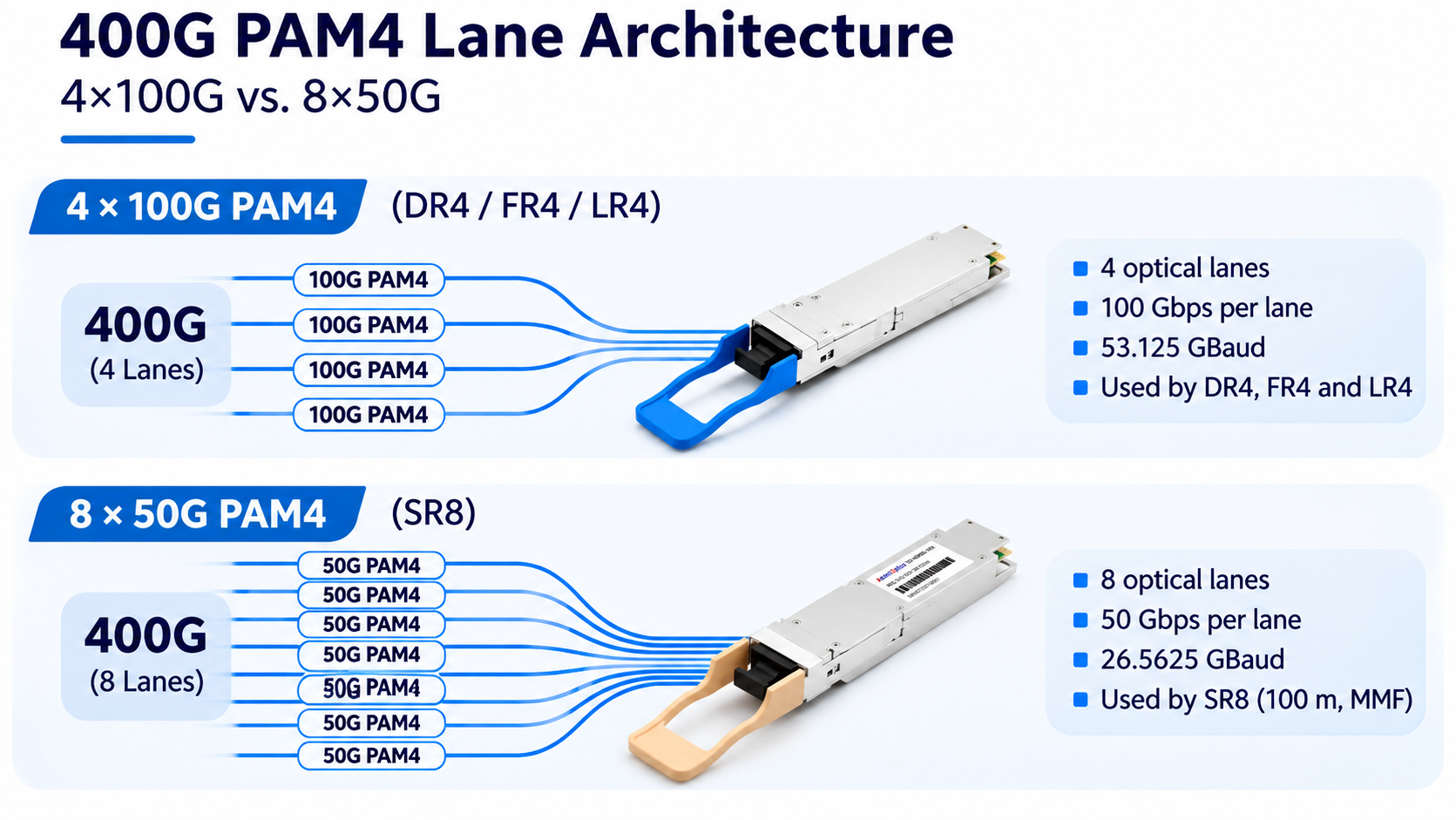
4x100G PAM4 (DR4, FR4, LR4)
The modern workhorse is 4x100G PAM4. Four optical lanes each carry 100 Gbps, for 400G total. Each lane runs at 53.125 GBaud. Multiply that by two bits per symbol and you get 106.25 Gbps raw, which after FEC overhead lands at 100 Gbps net.
This is the architecture behind DR4, FR4, and LR4 modules. It’s the reason a single QSFP-DD or OSFP can do 400G over single-mode fiber, and it’s what most new data center deployments standardize on.
8x50G PAM4 (SR8)
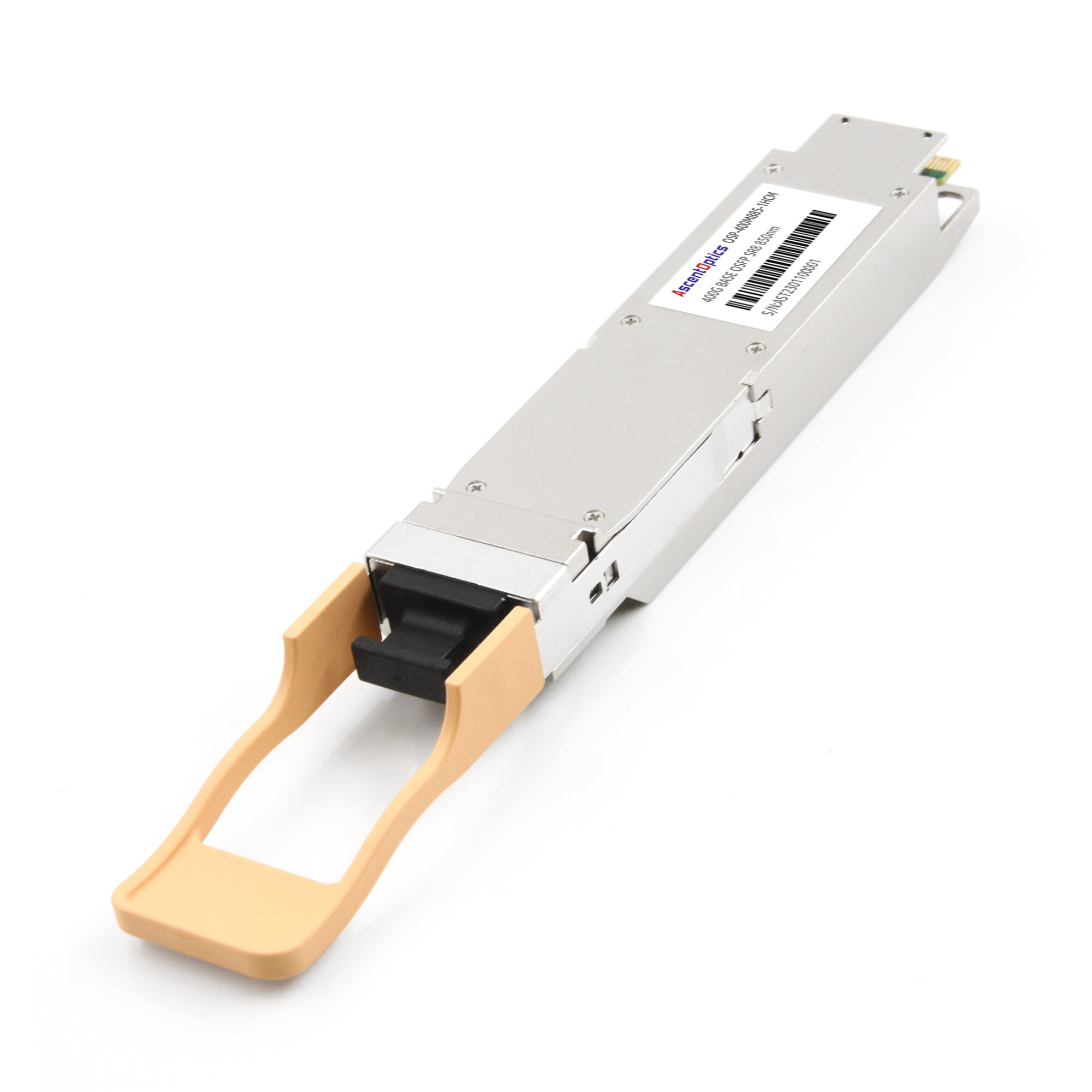
There’s a second arrangement: 8x50G PAM4, used by SR8 modules for very short reaches. Here eight lanes each carry 50 Gbps, running at 26.5625 GBaud per lane. SR8 targets 100 meters over multimode fiber, so it splits the signal across more, slower lanes to stay within multimode’s bandwidth limits.
The difference between 4x100G and 8x50G isn’t academic. It drives fiber type, connector type, and whether a module can break out into smaller links. We’ll cover that in the variant section below.
Typical DSP-Based 400G Module: 8x50G Electrical to 4x100G Optical
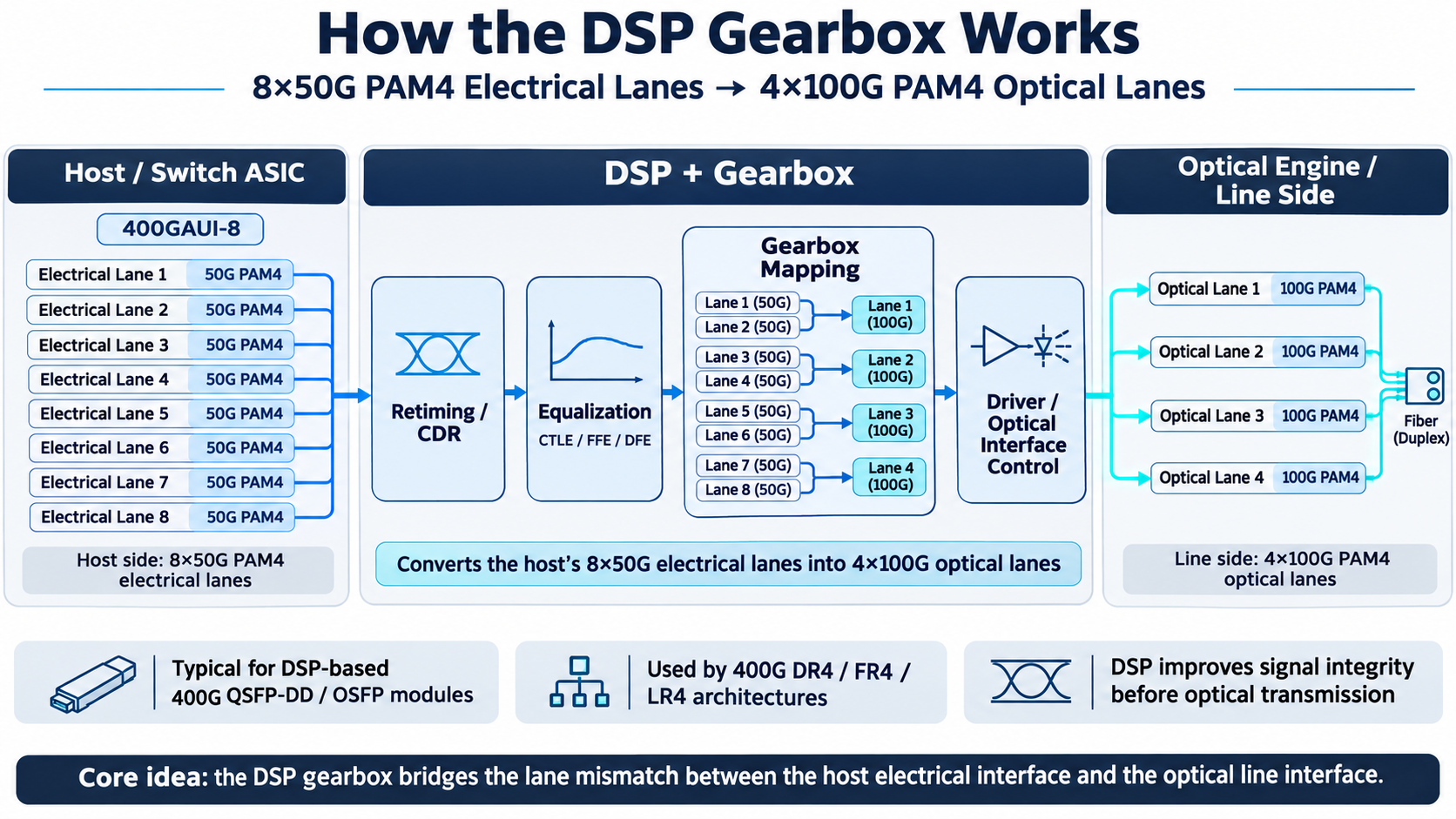
In a typical DSP-based 400G QSFP-DD implementation using a 400GAUI-8 host interface, the module receives eight electrical lanes and uses a gearbox to map them to four 100G optical lanes. Here’s the part most engineers never see. The switch and the optics don’t always speak the same lane language. A typical 400G QSFP-DD host interface, called 400GAUI-8, presents eight 50G PAM4 electrical lanes. A 4x100G optical module needs four 100G PAM4 optical lanes. Something has to translate between the two.
That something is the gearbox, usually embedded in the module’s DSP. It takes the host’s 8x50G electrical lanes and repackages them into 4x100G optical lanes.
400G DR4, FR4, and LR4: Key Differences
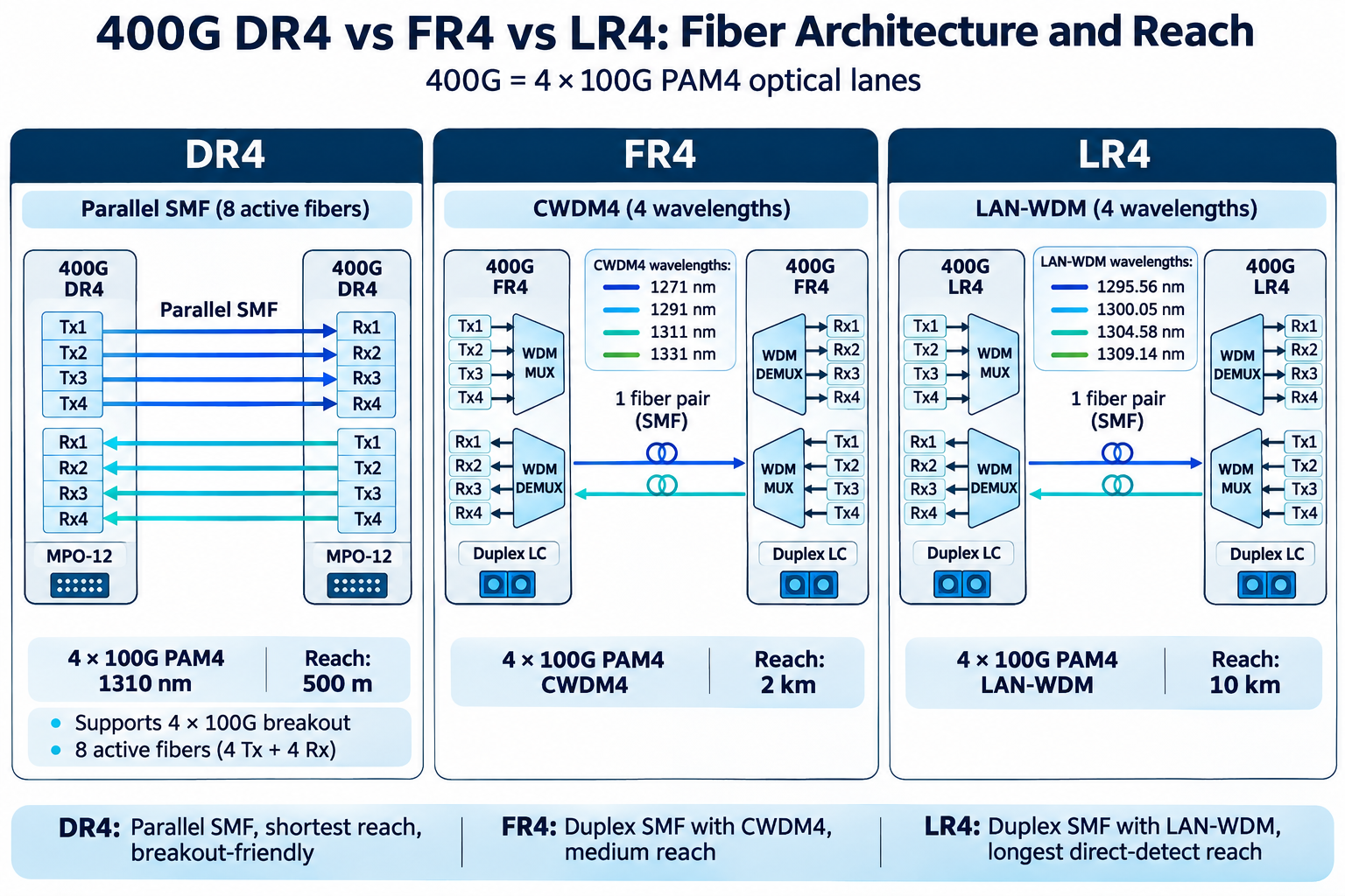
The three single-mode 4x100G variants differ mainly in reach, and reach drives everything else: wavelength plan, connector, and whether you can break out. Here’s the quick reference.
| Variant |
Lanes |
Reach |
Fiber |
Connector |
Wavelength |
Breakout |
| SR8 |
8x50G PAM4 |
100 m |
OM4 MMF |
MPO-16 |
850 nm |
8x50G |
| DR4 |
4x100G PAM4 |
500 m |
SMF |
MPO-12 |
1310 nm |
4x100G |
| FR4 |
4x100G PAM4 |
2 km |
SMF |
Duplex LC |
CWDM 1271 /1291 /1311 /1331 nm |
None |
| LR4 |
4x100G PAM4 |
10 km |
SMF |
Duplex LC |
LWDM 1295.56 /1300.05 /1304.58/1309.14 nm |
None |
DR4: Parallel Single-Mode, Built for Breakout
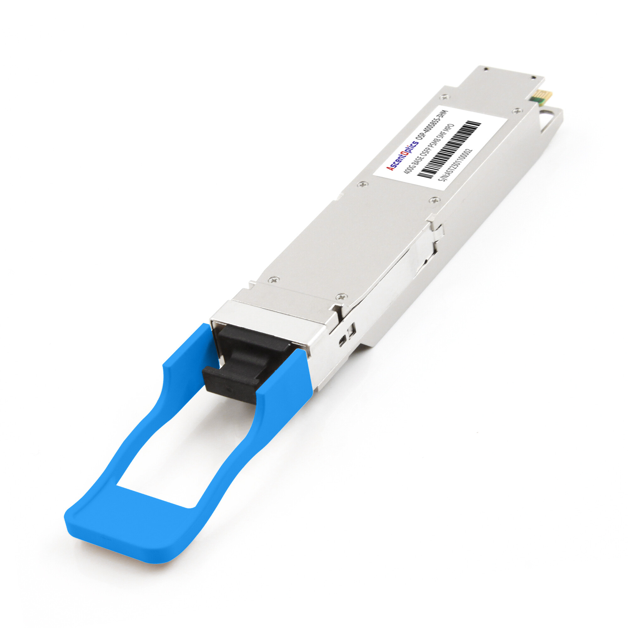
DR4 pushes 4x100G PAM4 down four parallel single-mode fibers at 1310 nm, reaching 500 meters over an MPO-12 connector. Because each lane stays on its own fiber, DR4 can break out into four independent 100G links. That makes it the go-to for spine-to-leaf connections where one 400G port fans out to four 100G ports.
FR4: The AI Cluster Favorite
FR4 runs the same 4x100G PAM4, but it multiplexes all four wavelengths onto a single fiber pair using CWDM4 at 1271, 1291, 1311, and 1331 nm. It reaches 2 km over ordinary duplex LC single-mode fiber.
The duplex LC part is why FR4 wins in AI and hyperscale environments. It plugs into the LC patch panels most facilities already have.
LR4: Maximum Direct-Detect Reach
400G LR4 uses four LAN-WDM wavelengths centered at approximately 1295.56 nm, 1300.05 nm, 1304.58 nm, and 1309.14 nm. Unlike FR4, which uses the CWDM wavelength grid, LR4 uses a tighter LAN-WDM wavelength spacing to support transmission distances of up to 10 km over single-mode fiber. It uses a duplex LC connector. That’s the practical ceiling for PAM4 direct-detect. Past 10 km, you’re looking at coherent 400G ZR optics, which is a different conversation.
When you’re choosing between these three, the decision usually comes down to distance and fiber plant:
- Under 100 m over existing multimode: SR8
- Under 500 m and you need breakout to 100G: DR4
- Up to 2 km over existing duplex LC: FR4
- Up to 10 km over duplex LC: LR4
If you want the full selection guide covering power, switch compatibility, and pricing across these variants, see our 400G QSFP-DD SR8/DR4/FR4/LR4 transceiver guide.
Signal Integrity and FEC in 400G PAM4
PAM4’s speed comes at a cost you can’t ignore on a real link. Cramming four levels into the same voltage swing shrinks the gap between levels, which makes the signal far more sensitive to noise.
The 9.5 dB SNR Penalty
Compared with NRZ, PAM4 has a significantly smaller vertical eye opening. At the same signal amplitude, the spacing between adjacent PAM4 levels is approximately one-third of the NRZ eye height. This results in a higher signal-to-noise requirement. Under idealized conditions, the theoretical SNR penalty is approximately 9.5 dB, although the actual optical power penalty depends on the system design and operating conditions.
Why KP4 FEC Is Mandatory
400G Ethernet uses KP4 FEC (RS(544,514)) to improve link reliability. It can correct up to 15 symbol errors per codeword and significantly reduce the post-FEC bit error rate when the pre-FEC error rate remains within the specified operating range. Under suitable operating conditions, the post-FEC BER can reach extremely low levels, such as \(10^{-15}\).
DSP Equalization
FEC can’t do the job alone. PAM4 at 53.125 GBaud needs a digital signal processor to clean up the signal before the receiver can even make a decision. The DSP applies three stages of equalization:
- CTLE (continuous-time linear equalizer): Compensates for high-frequency channel loss and improves signal quality.
- FFE (feed-forward equalizer): Uses linear filtering to mitigate both precursor and post-cursor inter-symbol interference (ISI).
- DFE (decision-feedback equalizer): Uses previous symbol decisions to compensate for post-cursor inter-symbol interference.
Each switch platform tunes these blocks differently, which is one reason the same module can perform slightly differently on Cisco, Arista, and Juniper hardware. That’s also why we test our modules per-platform rather than treating compatibility as a checkbox. For a deeper look at the signal-integrity mechanics, see VIAVI’s explainer on PAM4 and HYTOPTODEVICE’s signal-integrity analysis.
400G PAM4 Power and the Reach Wall
Two limits define where 400G PAM4 makes sense, and both trace back to that DSP and FEC we just covered.
Power Consumption
A 400G QSFP-DD PAM4 module typically consumes several watts of power, with actual consumption varying by optical reach, DSP architecture, and module design. In high-density switches, the cumulative power consumption of optical modules is an important consideration for system-level thermal management.
The 10 km Ceiling
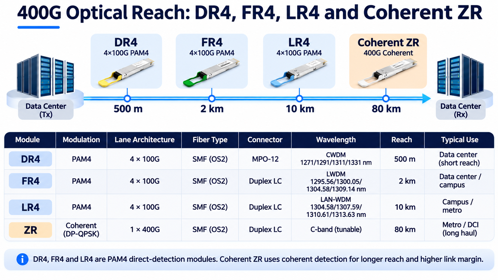
For common 400G direct-detect optical transceivers, standardized solutions such as DR4, FR4, and LR4 support reaches of up to 500 m, 2 km, and 10 km, respectively. For applications requiring longer transmission distances, 400G coherent optics, such as 400G ZR, provide an alternative solution. If your link spans a campus or metro area, you step up to coherent optics, which modulates both phase and amplitude and reaches 80 km and beyond.
That’s the line to remember: 400G PAM4 owns the data center. Coherent owns the distance. For links past 10 km, see our 400G ZR coherent optics guide.
400G PAM4 Form Factor Context
PAM4 is the modulation, not the package. It ships in a few form factors, and the choice between them is mostly about port density and thermal headroom.
QSFP-DD and OSFP
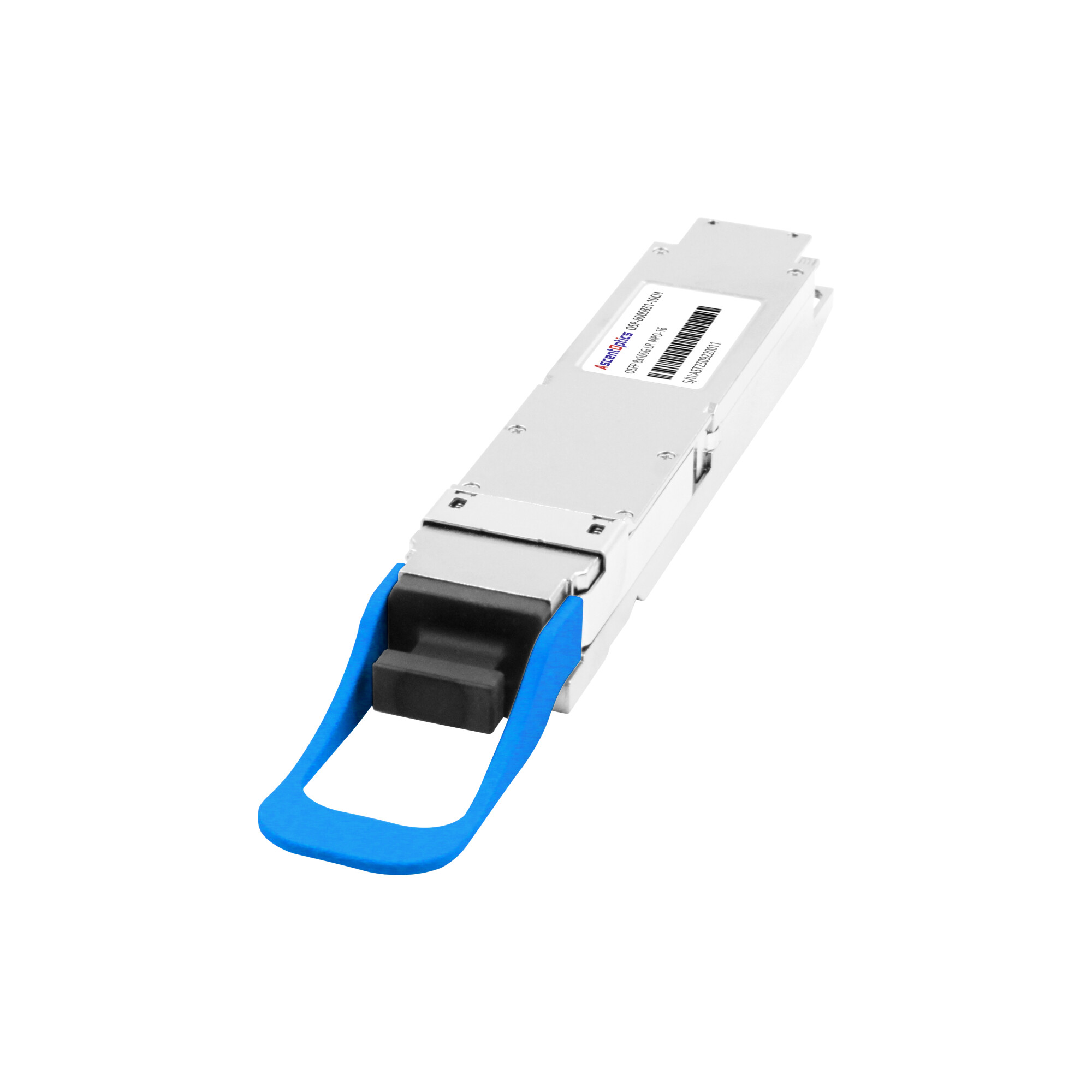
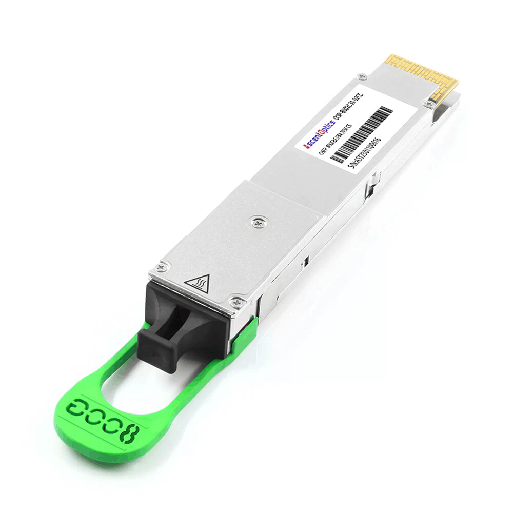
QSFP-DD and OSFP are two widely adopted form factors for 400G and 800G optical transceivers. QSFP-DD offers backward compatibility with QSFP28 and QSFP+ modules and supports high port density. OSFP features a larger physical design, providing additional thermal management capacity for high-power optical modules. The choice depends on switch platform compatibility, port density, and thermal requirements.
QSFP112 and the 100G-per-Lane Future
The 100G-per-lane PAM4 electrical interface is used in newer QSFP112 and QSFP112-DD form factors. QSFP112 supports four 112G-class electrical lanes for 400G applications, while QSFP112-DD expands the interface to eight lanes for 800G applications. These designs provide a foundation for higher-density, higher-speed optical connectivity.
If you’re planning past 400G, it’s worth understanding where the lane architecture goes next. Our 800G PAM4 guide covers the 8x100G and 4x200G architectures that follow, and the QSFP112 guide explains the form factor. For the comparison of PAM4 against the NRZ signaling it replaced, see PAM4 vs NRZ.
Conclusion
400G PAM4 technology enables high-speed data transmission by delivering two bits per symbol, making 400G Ethernet more efficient and scalable. Understanding the differences between DR4, FR4, and LR4, along with their lane architectures, transmission distances, and power requirements, helps network operators choose the right optical transceiver for their applications. As data center bandwidth demands continue to grow, PAM4 will remain an important signaling technology for high-speed optical connectivity.
Frequently Asked Questions
Why does 400G Ethernet use PAM4?
Because NRZ caps out around 25 to 32 Gbps per lane. PAM4’s two bits per symbol lets each lane reach 100 Gbps without pushing clock rates into loss-limited territory.
What is the difference between 400G DR4, FR4, and LR4?
Reach and wavelength plan. DR4 does 500 m over parallel single-mode at 1310 nm. FR4 does 2 km, and LR4 does 10 km, both using CWDM4 over duplex LC.
What baud rate does 400G PAM4 run at?
53.125 GBaud per lane for the 100G-per-lane variants. That’s 106.25 Gbps raw, which becomes 100 Gbps net after FEC overhead.
Does 400G PAM4 require FEC?
Yes. KP4 FEC is mandatory. It corrects a raw pre-FEC bit error rate around 1E-4 down to about 1E-15 post-FEC.
What is the difference between 400G SR8 and DR4?
SR8 uses 8x50G PAM4 for 100 m over multimode. DR4 uses 4x100G PAM4 for 500 m over single-mode and can break out to four 100G links.
How much power does a 400G PAM4 module draw?
Typically 7 to 12 W, most of it from the DSP handling the gearbox, equalization, and FEC.
When should I choose coherent instead of 400G PAM4?
Past about 10 km. PAM4 direct-detect owns the data center; coherent optics own the distance.
Post Views: 93