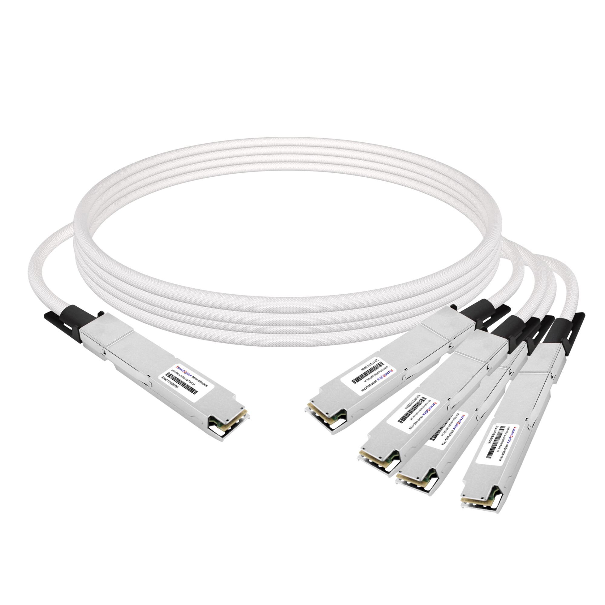
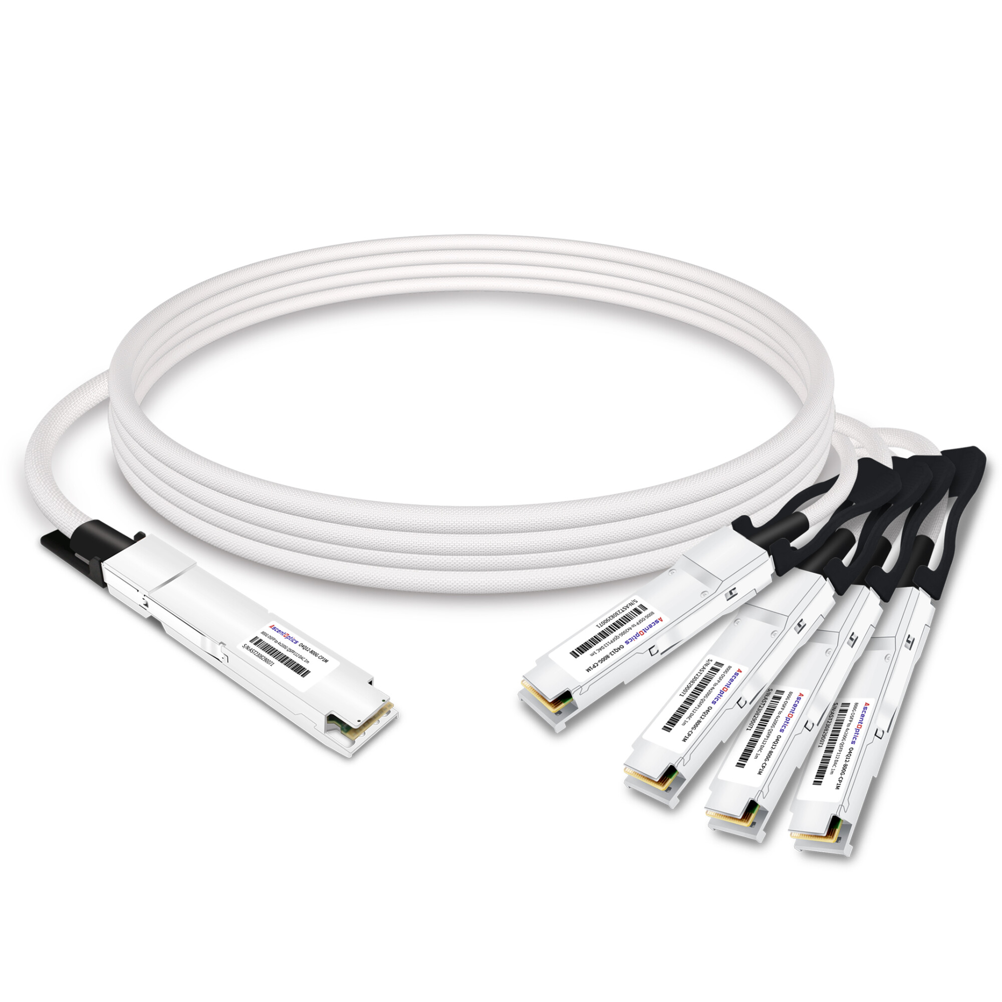
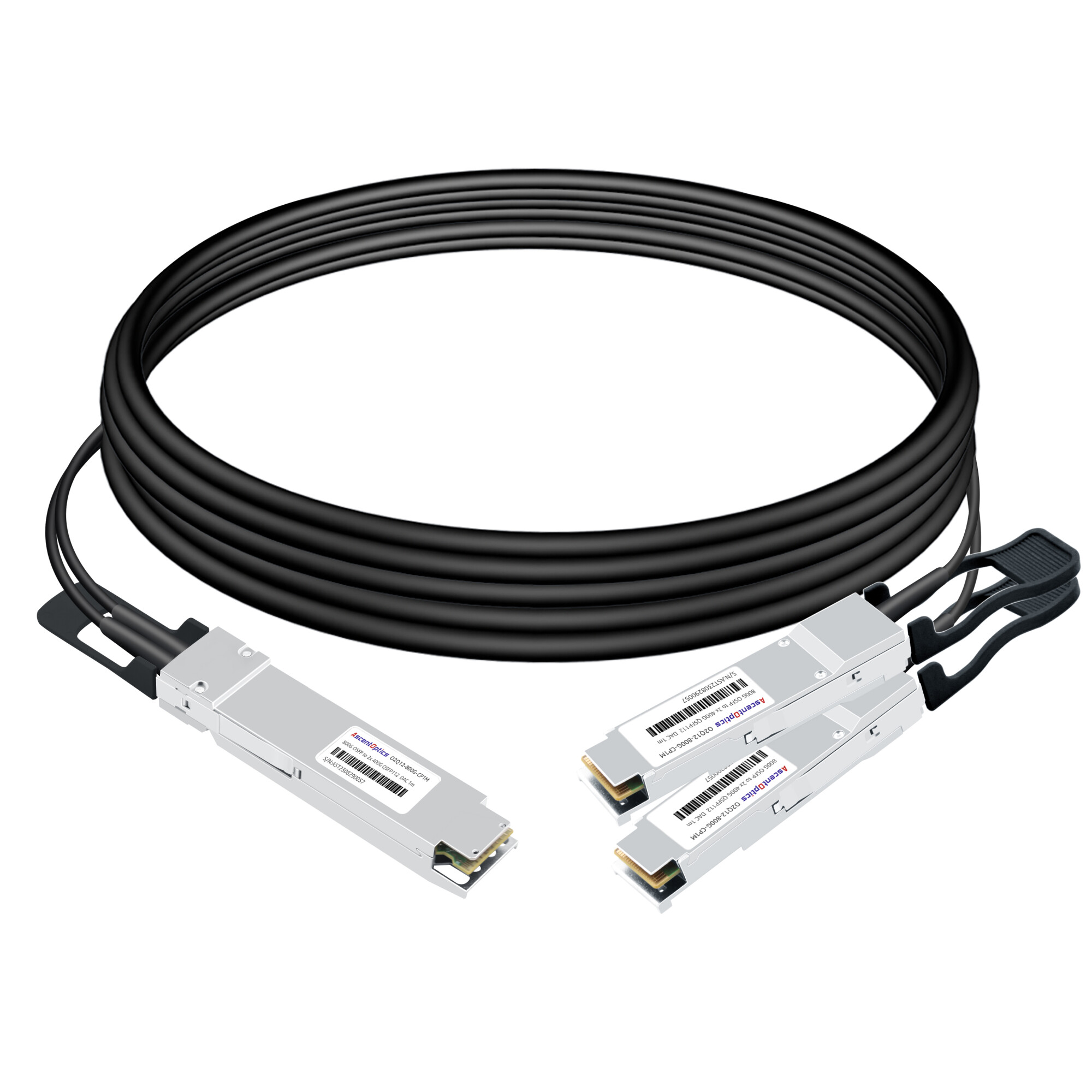
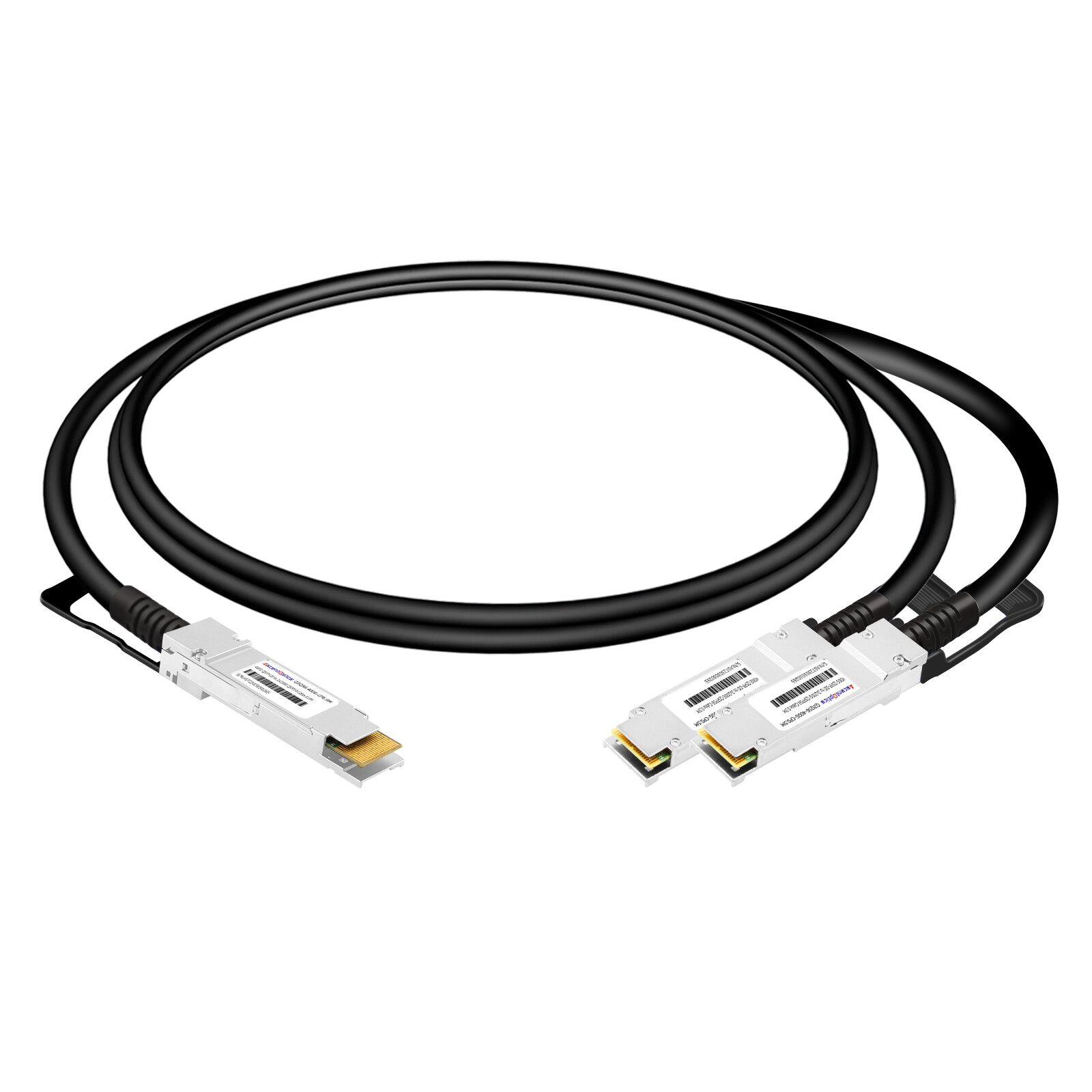
High-speed breakout DAC cables are designed for high-bandwidth port splitting and multi-channel connectivity, supporting flexible configurations such as 400G to 4x100G, 800G to 2x400G, and more. Tailored for short-reach data center interconnects, these plug-and-play solutions simplify cabling and reduce networking costs, facilitating seamless network upgrades and efficient port utilization.
What Is a Breakout DAC Cable?
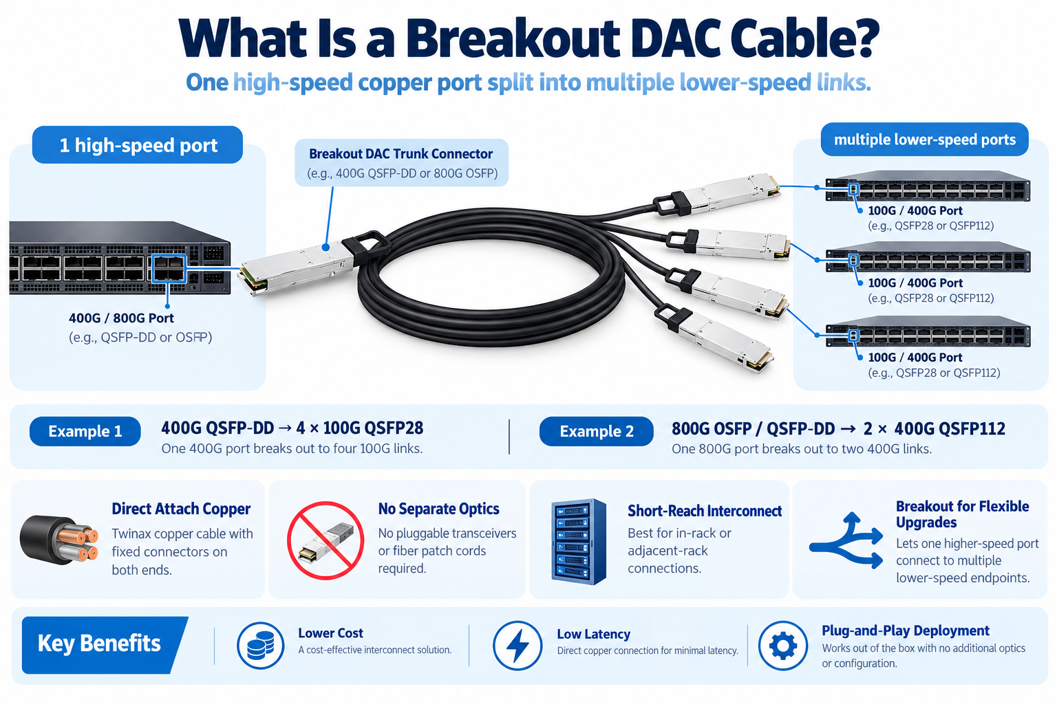
A breakout DAC cable is a direct attach copper assembly that divides one high-speed port into multiple lower-speed ports. A single 400G QSFP-DD port, for example, becomes four independent 100G QSFP28 links.
The connectors are fixed at both ends, and the entire path is copper. There are no optical transceiver modules to insert, no fiber to clean, and no separate optics to buy.
Breakout cables matter because data center upgrades never happen all at once. A network team might roll out 400G spine switches this quarter while leaf switches and server NICs stay at 100G for another year or two. A breakout DAC cable lets that 400G port operate at full capacity while still reaching the older 100G endpoints below it.
The trade-off is reach. Copper attenuates a signal quickly at 50G and 100G per lane, so breakout DAC cables are a short-reach tool. That’s why they live inside the rack or across an adjacent row, not between rows.
Breakout DAC Configurations by Speed
Breakout DAC cables span a wide range of speeds. The configuration you need depends on the parent port’s form factor and lane count, plus the speed of each leg you’re breaking out to.
| Parent Port |
Breakout |
Legs |
Typical Reach (Passive) |
| 40G QSFP+ |
4x 10G SFP+ |
4 |
Up to 5 m |
| 100G QSFP28 |
4x 25G SFP28 |
4 |
Up to 5 m |
| 100G QSFP28 |
2x 50G |
2 |
Up to 3 m |
| 200G QSFP56 |
2x 100G |
2 |
Up to 3 m |
| 400G QSFP-DD |
4x 100G QSFP28 |
4 |
0.5 to 2 m (active) |
| 400G QSFP-DD |
2x 200G QSFP56 |
2 |
Up to 2 m |
| 400G QSFP-DD |
8x 50G |
8 |
Up to 2 m |
| 800G QSFP-DD / OSFP |
2x 400G |
2 |
Up to 3 m |
| 800G QSFP-DD / OSFP |
4x 200G |
4 |
Up to 3 m |
| 800G QSFP-DD / OSFP |
8x 100G |
8 |
Up to 2 m |
Two configurations drive most of the real-world demand:
- 400G to 4x100G is the classic spine-to-leaf migration path, connecting a 400G spine port to four 100G endpoints.
- 800G to 2x400G is the default fan-out for AI fabrics and NVIDIA ConnectX-7 NICs.
Rate-Matched vs Gearbox Breakout
This is the concept that decides everything else, and it’s the one most product pages skip. Every breakout falls into one of two categories.
Rate-Matched Breakout
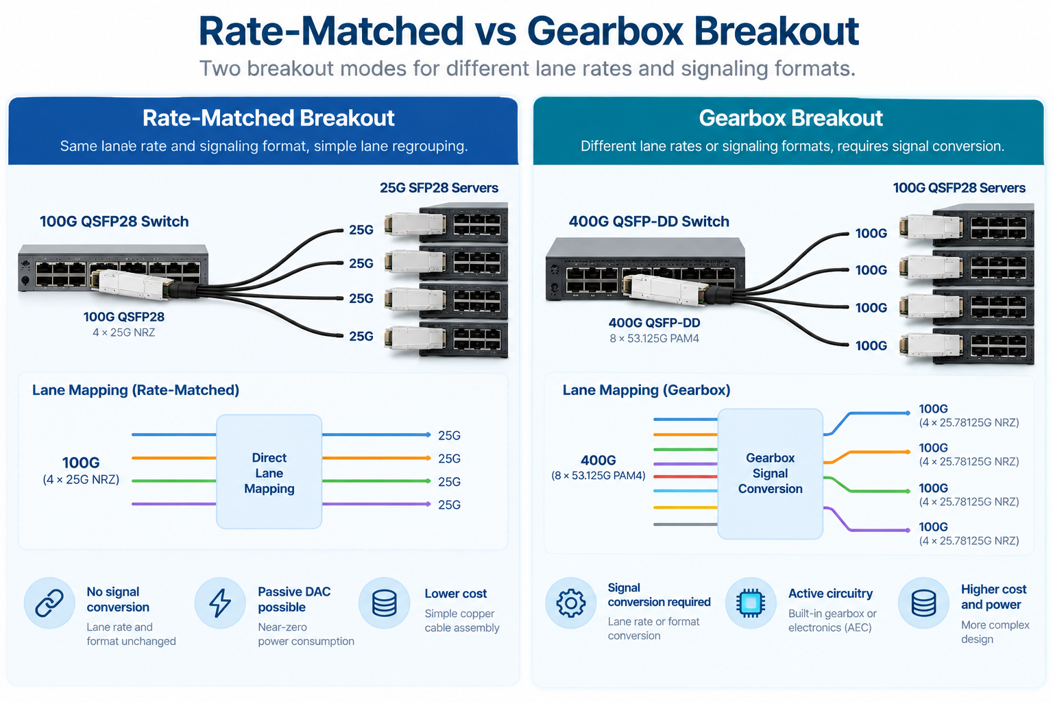
In a rate-matched breakout, the parent port’s lanes are simply regrouped into legs. The per-lane data rate and signaling format stay the same, and no signal processing happens inside the cable.
Take 100G QSFP28 to 4x25G SFP28. The parent runs four lanes at 25G NRZ each, and the four legs run 25G NRZ each. It’s a one-to-one regrouping. The cable is passive copper, drawing near-zero power, and it costs the least of any option. The same principle can apply to 800G-to-2×400G breakout. In a compatible configuration, an 800G port uses eight electrical lanes at approximately 106.25 Gb/s PAM4, while each 400G downstream port uses four lanes at the same rate and signaling format.
The breakout cable maps four lanes to each 400G link without changing the lane rate or modulation format. This makes passive DAC a potential option for short-reach connections. However, rate matching alone does not guarantee passive DAC compatibility. The host ports, lane mapping, channel loss budget, cable length, and device support must all be verified.
For AI clusters and high-density data centers, 800G-to-2×400G is a useful way to connect compatible 400G endpoints while maintaining flexible port utilization.
Gearbox Breakout
A gearbox breakout is used when the parent port and downstream links operate at different lane rates or signaling formats. Active circuitry may be required to convert the signals between the two interfaces.
A typical example is a 400G QSFP-DD port connected to four 100G QSFP28 ports. The 400G host interface commonly uses eight electrical lanes at approximately 53.125 Gb/s PAM4, while traditional 100G QSFP28 host interfaces use four electrical lanes at 25.78125 Gb/s NRZ.
Because the lane rates and signaling formats differ, this configuration requires an appropriate conversion architecture. Depending on the implementation, the cable assembly may incorporate a gearbox or other active circuitry.
An active electrical cable (AEC) can provide signal conditioning and, in supported designs, the circuitry needed for rate conversion. However, not every AEC includes a gearbox, so the product specifications must be checked carefully.
The key takeaway: Do not assume that every 400G-to-4×100G breakout cable has the same internal architecture. Verify the cable’s supported host interfaces, conversion capabilities, and switch compatibility before ordering.
Here’s the pattern in one view:
If a configuration sits in the gearbox row, budget for active electronics. If it sits in the rate-matched rows, passive copper will do the job.
Passive vs Active Breakout DAC Cables
Once you know whether your breakout is rate-matched or gearbox, the cable type decision gets simpler. You’re choosing between three options.
Passive breakout DACs are pure twinax copper with no electronics. They work for rate-matched configurations, which is why they’re the standard for 100G to 4x25G, 400G to 2x200G, and 800G to 2x400G.
Reach is short, typically 0.5 to 3 meters depending on wire gauge and lane rate. Power is effectively zero, under 0.1W per end. Cost is the lowest of any breakout option, and latency is effectively none. For intra-rack links, passive is almost always the right call.
An active electrical cable (AEC) integrates active electronics into the cable assembly to improve signal integrity and support reliable high-speed electrical connections. Depending on the design, these electronics may include redrivers, retimers, or other signal-processing components.
AECs can support longer reach than comparable passive copper cables in applications where additional signal conditioning is required. Some specialized designs may also incorporate rate-conversion circuitry, but this capability is not inherent to every AEC.
Before selecting an AEC breakout cable, check its supported data rates, electrical interfaces, power consumption, reach, and compatibility with the target switch or NIC.
Breakout AOC
Active optical cables replace copper with fiber and integrated optics. A breakout AOC converts the electrical signal to light inside the connector and transmits over fiber legs.
Reach jumps to 30 meters or more, which is why AOC wins for inter-rack runs. The trade-offs are power, up to 10W at the host end, and cost, which runs several times higher than copper. Weight drops, though. A four-leg copper bundle is stiff and thick, while an AOC breakout routes like a ribbon.
| Cable Type |
Reach |
Power (Host End) |
Cost |
Best For |
| Passive DAC |
0.5 to 3 m |
Under 0.1W |
Lowest |
Rate-matched, intra-rack |
| AEC |
0.5 to 3m |
2.5 to 4.5W |
Mid |
Gearbox or extra reach |
| AOC |
1 to 30 m+ |
Up to 10W |
Highest |
Inter-rack, long reach |
Comparing passive and active options for your topology? See how breakout choices fit the broader 400G OSFP DAC vs AOC decision.
Reach, Wire Gauge, and Signal Integrit
Reach in a breakout DAC is governed by wire gauge and lane rate. Thicker wire carries signal farther but bends less easily.
Breakout bundles commonly use 26 AWG to 30 AWG twinax. At the lower speeds, 24 AWG can push a 10G breakout past 5 meters. At 800G, where each lane runs 100G PAM4, copper reach collapses, and even 26 AWG tops out around 2 to 3 meters. That’s the core reason AI fabrics stay short-reach on copper and switch to AOC or optics beyond the rack.
Bend radius matters more with breakout bundles than with a single cable. A four-leg or eight-leg assembly concentrates copper into one thick trunk near the parent connector. Routing that trunk through a sharp bend degrades signal integrity and can damage the twinax pairs. Plan cable routes so the trunk stays straight and only the individual legs bend.
Compatibility: Port Breakout Mode and Vendor Coding
A breakout DAC cable only works when the switch agrees to run in breakout mode. That’s a software setting, not a hardware feature, and it’s the single most common reason a breakout link stays down.
On most switches, you have to explicitly configure a port for breakout. A 400G port won’t automatically fan out to four 100G interfaces. It has to be set to the right mode, whether 4x100G, 2x200G, or 8x50G, in the CLI or management interface. Check the switch’s data sheet first, because breakout support varies by model and ASIC even within the same vendor’s lineup.
Vendor coding is the second hurdle. Breakout cables carry an EEPROM that identifies them to the host. Some platforms, Cisco and Arista especially, reject cables that don’t carry the expected vendor code.
Third-party manufacturers can program those codes, but you have to specify the target vendor when you order. An MSA-generic cable on a strict switch can leave the port down with no obvious error.
The Common Management Interface Specification (CMIS) governs how a cable reports its status and per-lane diagnostics. The Wave2Wave CMIS breakout guide walks through the host and media lane mapping codes if you need the low-level detail. Your switch firmware also has to support the cable’s CMIS version for diagnostics to report correctly.
Breakout DAC in Data Center and AI Deployments
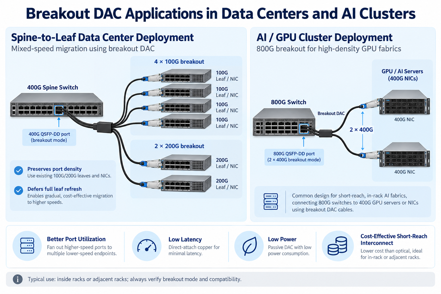
Breakout DACs earn their keep in two places: mixed-speed spine-to-leaf fabrics and AI GPU clusters.
In a spine-to-leaf design, 400G spine switches fan out to 100G or 200G leaf switches and server NICs. Breakout cables let a single spine port serve four endpoints instead of one, which preserves port density and defers the cost of a full leaf refresh. The C-LIGHT DAC breakout reference catalogs the CR lane-count designations behind these configurations if you want to dig into the standards.
In AI clusters, 800G switches fan out to 2x400G links that connect to NVIDIA ConnectX-7 NICs and Quantum-2 or Spectrum-4 ports. Copper stays dominant inside the rack because it’s cheap, low-latency, and near-zero-power, which matters when a single rack holds hundreds of these links. For the 800G side specifically, our OSFP breakout cable guide covers the 800G to 2x400G lane mapping in more detail.
Cable management gets serious at this density. A 32-port switch using four-leg breakouts produces 128 downstream cable ends in one rack. Keep it manageable with a few habits:
- Route trunks along the rack sides, away from the front-to-rear airflow path.
- Keep the trunk straight and let only the individual legs bend.
- Label every leg at both ends. A mislabeled leg in a dense AI rack can take an hour to trace.
Frequently Asked Questions
What is a breakout DAC cable?
A breakout DAC cable is a direct attach copper assembly that splits one high-speed port into multiple lower-speed ports, such as a 400G QSFP-DD port into four 100G QSFP28 links. It uses twinax copper with fixed connector ends and no separate optics.
Does 400G to 4×100G breakout require active electronics?
It depends on the electrical interfaces and cable architecture. A typical 400G QSFP-DD host interface using 50G-class PAM4 lanes differs from traditional 100G QSFP28 interfaces using 25G-class NRZ lanes. Such a configuration requires an appropriate conversion solution, which may involve an active cable assembly with gearbox circuitry. Verify the exact cable specifications and host compatibility before ordering.
What is the difference between rate-matched and gearbox breakout?
A rate-matched breakout regroups lanes without changing the rate or encoding, so passive copper works. A gearbox breakout converts the signaling format, which requires active electronics inside the cable.
How far can a breakout DAC cable reach?
Breakout DAC reach depends on the data rate, cable gauge, cable design, and host electrical interface. Passive DACs are generally used for short-reach connections, while AECs can support longer electrical links in compatible configurations. For longer distances, breakout AOCs may be a suitable alternative. Always check the manufacturer’s specifications for the supported reach of a specific cable.
What is the difference between breakout DAC and AOC?
Breakout DAC is copper with no optical conversion, offering the lowest cost and power but short reach. Breakout AOC uses fiber and integrated optics for much longer reach at higher cost and power.
Does my switch support breakout mode?
Breakout support varies by switch model, port implementation, and software configuration. Check the switch documentation to confirm the supported breakout modes, downstream interface speeds, and cable compatibility. Configure the required port mode before deployment, and verify that the cable’s electrical interfaces and coding are supported by the host device.
Post Views: 117