For short-reach 400G interconnects, cable selection affects equipment compatibility, deployment cost, cabling space, and power consumption. QSFP112 direct attach copper (DAC) cables are often an efficient choice for qualified in-rack connections. This guide explains the architecture, passive and active alternatives, breakout configurations, and deployment checks needed before selecting a cable.
What Is a QSFP112 DAC Cable?
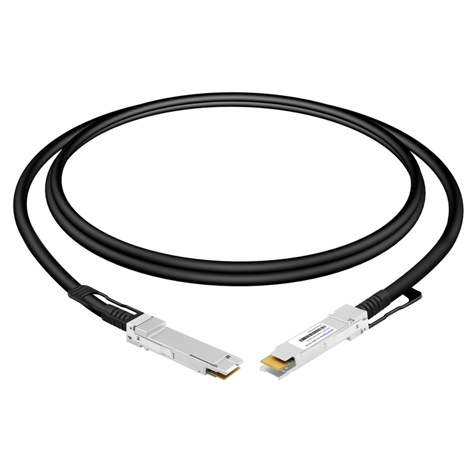
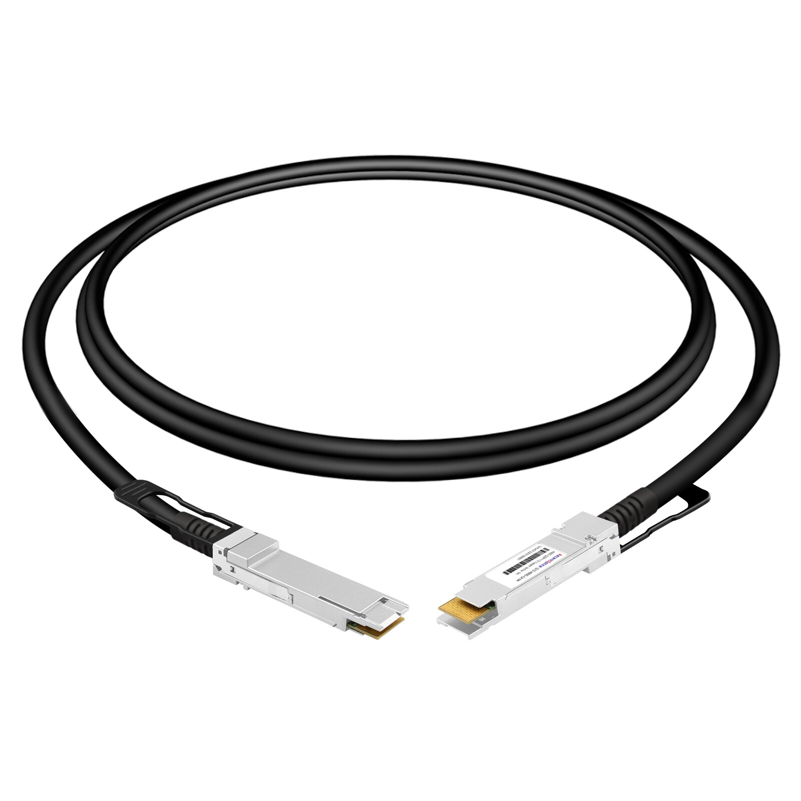
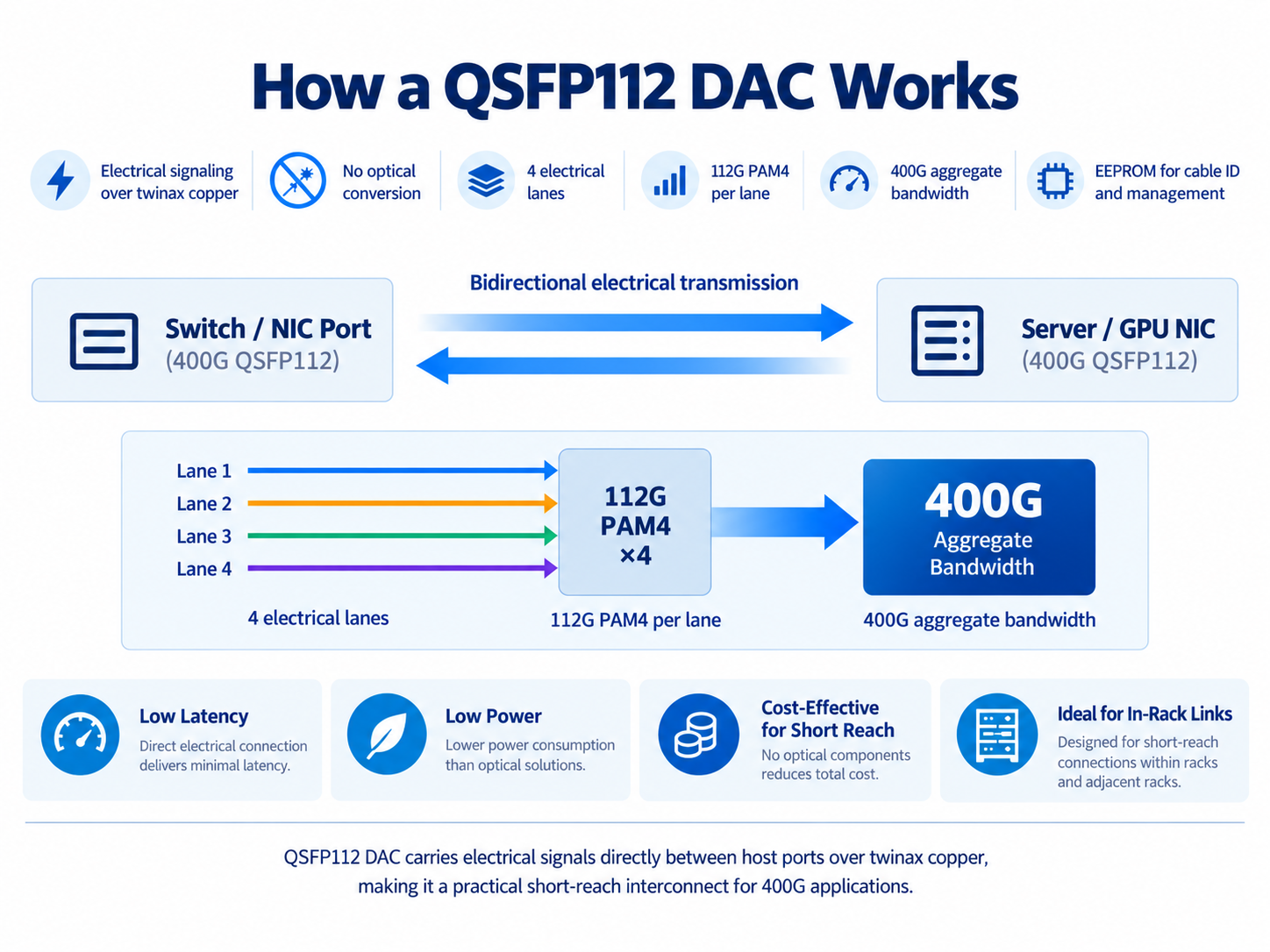
A QSFP112 DAC is a direct attach copper cable with a QSFP112 connector permanently attached to each end. It carries electrical signals over twinax copper wire, with no optical conversion anywhere in the link.
The QSFP112 Form Factor
QSFP112 is a four-lane pluggable form factor defined by the QSFP112 Multi-Source Agreement (MSA), supporting electrical signaling at approximately 100 Gb/s per lane. In a 400GbE implementation, four 100G-class lanes deliver a nominal 400 Gb/s Ethernet link; PAM4 electrical line rates are approximately 106.25 Gb/s per lane, including physical-layer overhead. The “112” designation refers to the broader 112G-class electrical interface technology rather than four 112 Gb/s Ethernet payload lanes.
QSFP112 belongs to the four-lane QSFP mechanical family and has a similar front-panel footprint to earlier QSFP generations. However, matching physical dimensions do not establish electrical or protocol compatibility. Host connector, thermal design, signaling rate, firmware, and supported cable types must all be verified.
IEEE 802.3ck defines electrical-interface specifications based on 100 Gb/s-per-lane signaling and is relevant to 400GBASE-CR4 operation over a four-lane copper medium. The QSFP112 MSA addresses form-factor and host-module interfaces; these documents serve different purposes.
How a QSFP112 DAC Works
A passive QSFP112 DAC has captive QSFP112 plugs and differential twinax copper pairs that carry high-speed electrical signals between compatible host ports. No electro-optical conversion occurs. A host transmitter and receiver provide the signal processing needed to operate across the specified copper channel.
Passive copper requires no signal-path retimer or optical engine, so its incremental cable power and latency are usually very low. The cable assembly may include memory and identification circuitry. Available management data depend on the cable implementation and should not be assumed to include optical-style digital diagnostics.
QSFP112 DAC vs. Optical Transceiver
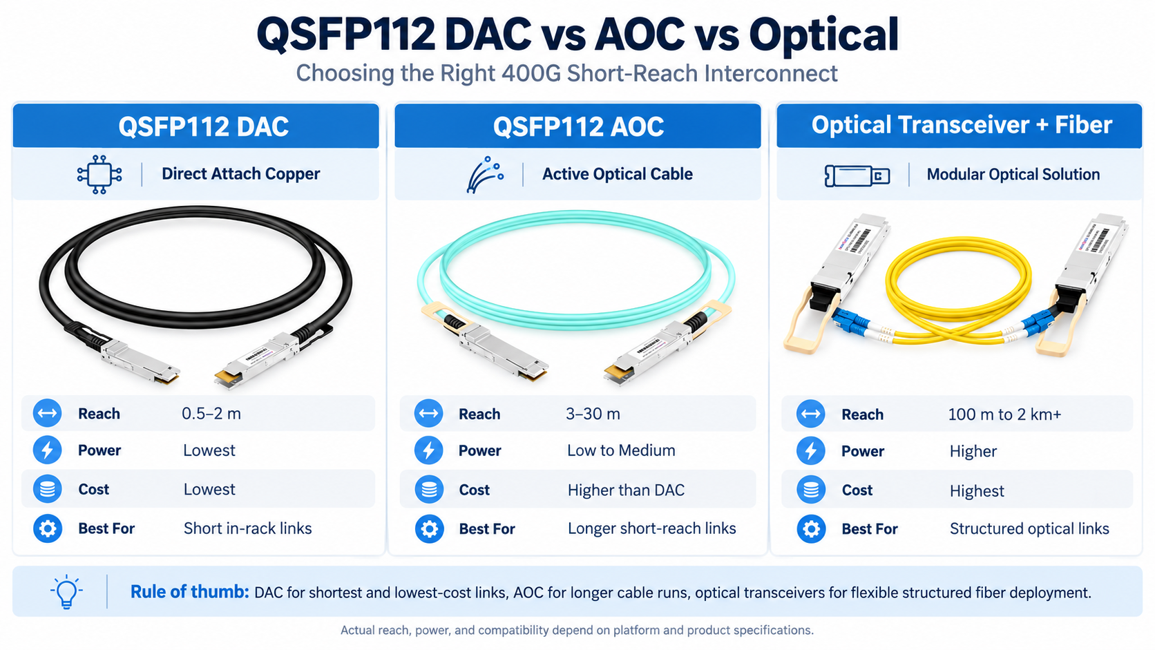
A passive QSFP112 DAC and a compatible optical link can solve different reach and cabling requirements:
- DAC: usually lower cable-side power and cost at short, validated distances; copper thickness and routing space can be limiting.
- Optics or AOC: supports longer cable runs and potentially easier routing, but usually requires active electronics and higher cable-side power.
For many links around 1–2 meters, a qualified passive DAC is attractive. Longer links may need thicker passive copper, an ACC/AEC, an AOC, or pluggable optics depending on the actual platform and cable specifications.
QSFP112 DAC Types: Passive vs. Active Copper
QSFP112 copper interconnect options include passive DAC and active electrical cable assemblies. Product labels differ across manufacturers, so identify whether the cable is passive, analog-conditioned, or retimed.
A passive QSFP112 DAC contains high-speed twinax conductors without active redrivers or retimers in the signal path. It is often the simplest and lowest-power option for short links.
Passive reach depends on wire gauge, cable design, insertion loss, host transmitter/receiver capabilities, and the applicable channel budget. Common commercially offered lengths are around 0.5–2 meters, but availability and approved reach must be checked for each SKU and host combination:
- 30 AWG: commonly used for shorter, more flexible cable assemblies; verify the supported length.
- 26 AWG: thicker copper can improve insertion-loss performance but increases cable stiffness; verify the supported length.
Passive DAC assemblies generally have very low cable-side power consumption, although the exact figure depends on their management circuitry. Reliability also depends on cable workmanship, connector quality, handling, and mechanical strain.
Active QSFP112 DAC (ACC) and AEC
When passive copper does not satisfy the channel budget, an active electrical solution may extend the usable reach.
An active copper cable (ACC) typically uses analog equalization or amplification in the cable ends to compensate for channel loss. Supported distances and power vary by product and platform; a few meters is a typical application range, not a guaranteed specification.
An active electrical cable (AEC) typically uses digital retiming to recover and retransmit signals, which can improve channel margin at longer distances. AEC power and latency are generally higher than those of passive DAC, and must be checked against the specific product datasheet.
Terms such as “active DAC” may refer to different implementations. Check whether the assembly is an ACC with analog signal conditioning or an AEC with retimers, and confirm protocol, FEC, latency, power, and interoperability.
Cable Gauge and Bend Radius
AWG matters more at 112G than it did at 25G or 50G. Thicker conductors (lower AWG number) carry high-frequency signals further but make the cable stiffer and harder to route.
A finer 30 AWG cable may be easier to route than 26 AWG copper, while thicker conductors can enable longer links. Do not use one universal minimum bend-radius figure: follow the selected manufacturer’s datasheet and installation instructions, and avoid sharp bends or excessive stress near the plug.
QSFP112 DAC vs. QSFP-DD DAC: Key Differences
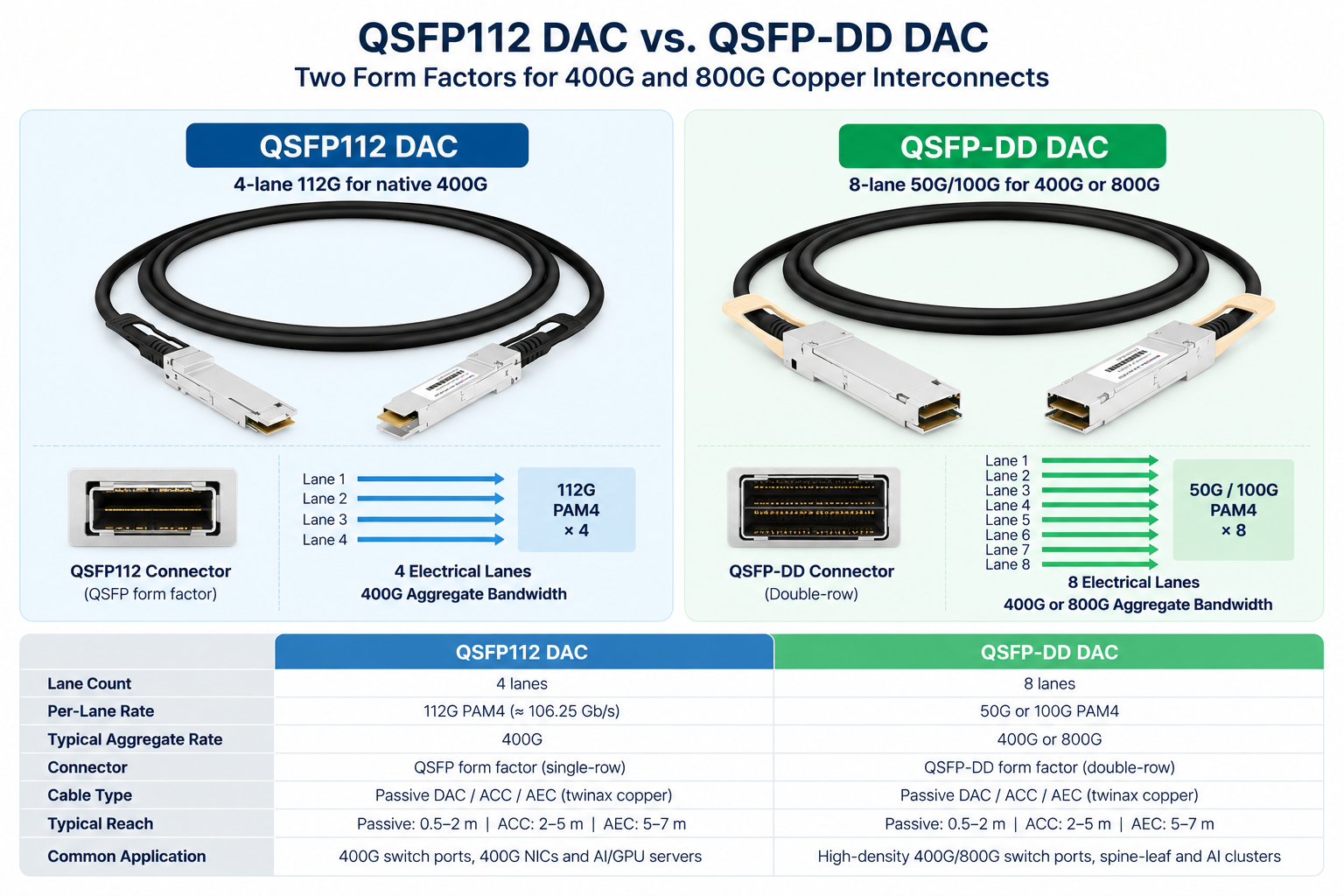
Both form factors support high-speed copper interconnects, but they have different lane counts and connector/contact structures. Select the cable according to the actual host ports and supported electrical interface.
QSFP112 provides four electrical lanes for a 400G-class connection. QSFP-DD uses eight host electrical lanes and has additional contact rows; different QSFP-DD generations support different electrical lane rates, including 400G and 800G implementations. Connector fit alone does not ensure a usable link.
The practical consequences:
| Attribute |
QSFP112 DAC |
QSFP-DD DAC |
| Lanes |
4 x 100G-class |
8 x 50G-class (400G) or 8 x 100G-class (800G) |
| Native speed |
Typically 400G-class |
400G- and 800G-class, by generation |
| Connector size |
QSFP-family four-lane plug |
QSFP-DD, eight-lane dual-row interface |
| Port density |
Depends on complete platform design |
Depends on complete platform design |
| Common role |
Selected 400G adapters/NICs |
400G/800G host systems, model-dependent |
QSFP112 has a compact four-lane footprint, while QSFP-DD offers eight electrical lanes in a related pluggable family. System-level port density and bandwidth density depend on chassis design, port configuration, cooling, and supported line rates; one form factor is not categorically denser than the other.
For a QSFP112 NIC, use a qualified QSFP112-ended cable or supported breakout assembly. For an OSFP- or QSFP-DD-equipped switch, match the switch-side connector and the specific breakout mode; do not assume a straight QSFP112-to-QSFP112 DAC fits both devices.
QSFP112 DAC vs. AOC: When to Choose Copper
The choice between copper and optical cable is primarily driven by reach, compatibility, cable management, and the total cost and power of the selected link.
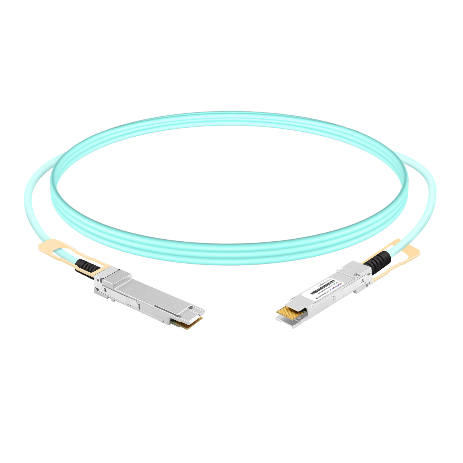
An active optical cable (AOC) integrates optical engines into its end connectors and uses fiber between them. AOCs are offered in multiple lengths, including short runs and tens of meters; exact available lengths, power requirements, and host support vary by product.
| Attribute |
QSFP112 DAC (passive) |
QSFP112 ACC/AEC |
QSFP112 AOC |
| Reach |
Often ~0.5–2 m; SKU dependent |
Several meters; product dependent |
Short to tens of meters or more; SKU dependent |
| Power per end |
Very low; SKU dependent |
Higher; ACC/AEC differ |
Higher; module dependent |
| Relative cost |
Often lowest at short reach |
Varies with electronics |
Varies by vendor/reach |
| Latency |
Minimal cable-added latency |
ACC low; AEC adds retiming |
Low, includes optical conversion |
| Weight/bulk |
Copper may be bulky |
Design dependent |
Fiber cable often easier to route |
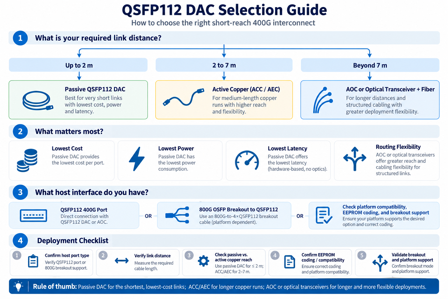
The rule of thumb is distance-based:
- Short in-rack links: first assess a validated passive QSFP112 DAC.
- Longer copper links: check whether a qualified ACC or AEC supports the required length and port combination.
- Where copper cannot meet the required reach, weight, or routing conditions: consider an AOC or optical transceivers with suitable fiber.
Passive DAC frequently has a lower purchase price and cable-side power requirement than active optical alternatives for short runs. However, the cost difference is product- and volume-dependent; compare actual quotations and host requirements rather than assuming a fixed percentage saving.
800G Breakout DACs and the QSFP112 AI Cluster
Some AI-networking architectures use high-bandwidth OSFP switch ports and lower-bandwidth QSFP112 adapter ports. A breakout copper cable can connect them when the switch supports the requested breakout mode and the cable is qualified for the target NICs or DPUs.
800G OSFP to 2 x 400G QSFP112
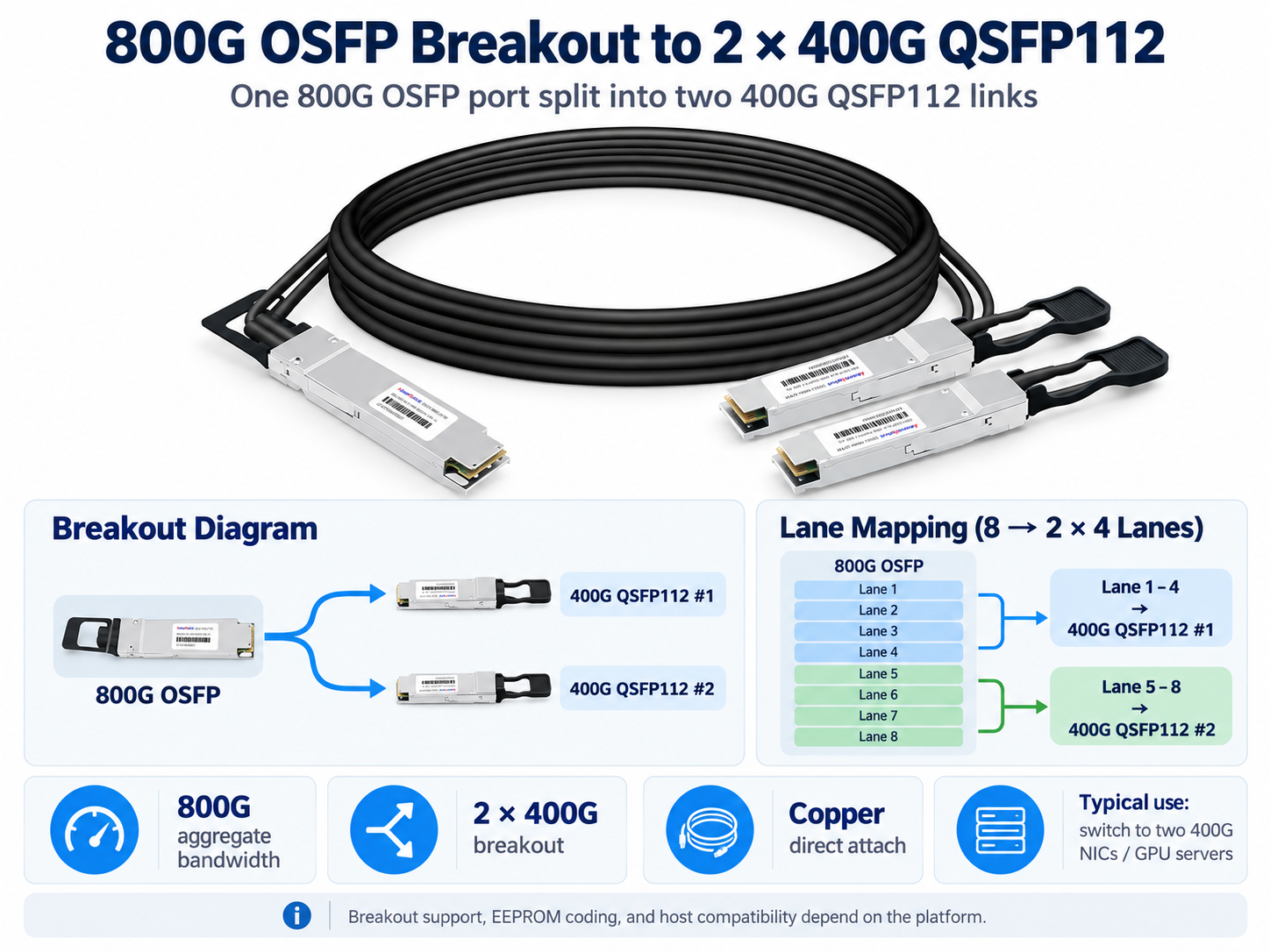
A supported 800G OSFP-to-2×400G QSFP112 breakout cable maps two independent groups of four high-speed electrical lanes to two QSFP112 ends. The switch must support the corresponding 2×400G port configuration and appropriate firmware/protocol settings.
This arrangement can connect two compatible 400G adapters to one eight-lane OSFP switch cage. Confirm whether the switch presents two separate 400G logical ports and whether the exact cable part number is approved for the selected NVIDIA or third-party platform.
Certain qualified assemblies provide 800G OSFP-to-4×200G QSFP112 breakout. This is a distinct lane-mapping and link-mode configuration, not a feature of every OSFP port. Verify 4×200G breakout support, connector-side signaling, and downstream adapter capabilities before ordering.
The NVIDIA Ecosystem
NVIDIA Quantum-2 NDR InfiniBand and Spectrum-4 SN5600 Ethernet switch systems use twin-port OSFP switch-side connections. Compatible ConnectX-7 adapters may be offered with either QSFP112 or OSFP interfaces, while BlueField-3 400G configurations use QSFP112. Consequently, a typical switch-to-adapter copper connection may require an OSFP-to-QSFP112 breakout assembly, rather than QSFP112 plugs on both ends. Always validate the exact switch and adapter SKUs.
Signal Integrity, Reach, and Standards
Higher per-lane symbol rates tighten the electrical-channel loss and noise budget. That is why qualified passive 100G/lane copper assemblies are commonly shorter than earlier-generation QSFP28 DACs.
Why 112G Copper Reach Is Short
At 100G-class PAM4 signaling, insertion loss, return loss, crosstalk, and jitter can materially affect the received eye margin. PAM4 uses four amplitude levels and offers less noise margin than a comparable two-level signaling scheme. Channel design and forward error correction help achieve the required link performance.
Compared with earlier 25G NRZ-per-lane passive DACs, 100G/lane copper generally needs tighter channel control and shorter cable lengths. Do not treat 2 meters as a universal QSFP112 maximum; rely on the cable vendor’s validated specifications and host channel budget.
Standards Compliance
Apply the specifications relevant to the actual Ethernet or InfiniBand implementation, cable type, and management interface:
- IEEE 802.3ck: defines applicable 100 Gb/s-per-lane electrical interfaces, including 400GBASE-CR4-related requirements for Ethernet.
- QSFP112 MSA: specifies relevant module, connector, electrical, mechanical, thermal, and management characteristics.
- SFF-8636 or CMIS: management memory maps may differ by cable and host implementation; optical-style DOM fields are not guaranteed on passive copper.
- OIF CEI-112G: describes relevant 112G-class electrical interface technologies; specific variants and compliance claims should be identified.
Compliance is an important foundation, but it does not by itself guarantee interoperability. Confirm vendor qualification, firmware support, port configuration, FEC, cable coding, and error-rate performance in the final system.
Compatibility and Deployment Best Practices
Switch and NIC Compatibility
Host-side port support, signaling technology, and cable qualification are at least as important as EEPROM coding. Cable EEPROM fields identify the assembly and can influence vendor acceptance checks, but coding cannot make an unsupported electrical or breakout mode work.
MSA-aligned identification does not imply that every vendor host will accept the cable. Verify allowed third-party cable policies, cable identifier requirements, and the supported cable part-number list for each switch or adapter.
On NVIDIA platforms, distinguish the OSFP switch-side interface used by Quantum-2 and relevant Spectrum-4 models from the QSFP112 adapter-side interface used by certain ConnectX-7 and BlueField-3 configurations. Match the qualified cable assembly to both endpoints; third-party switch compatibility must be verified model by model.
Installation and Troubleshooting
A short validation checklist prevents avoidable deployment issues:
- 1. Identify both endpoint port form factors and the exact link speed, protocol, and breakout mode.
- 2. Verify the cable SKU, gauge, length, supported reach, and host-side power budget.
- 3. Seat connectors fully and observe the manufacturer’s cable bend-radius and strain-relief guidance.
- 4. Check cable identifiers, firmware, FEC configuration, switch-port mode, and the vendor interoperability list.
If a link fails, inspect link negotiation or training status, cable identity, configured port speed, and FEC settings. For intermittent errors, investigate connector seating, cable routing, thermal conditions, and pre-/post-FEC error counters. A shorter or more suitable cable may help when the channel margin is insufficient.
Read management information that the selected cable actually exposes. Passive copper does not necessarily provide transceiver-style temperature, optical power, or diagnostic monitoring. Switch and NIC counters are often more useful for assessing link quality.
Frequently Asked Questions
What is a QSFP112 DAC cable?
A QSFP112 DAC is a short-reach twinax copper assembly with QSFP112 plugs. Four 100G-class electrical lanes can support a nominal 400G-class connection without optical conversion when both host ports and the cable are qualified.
How far can a QSFP112 DAC reach?
Many passive 400G QSFP112 DAC products are offered at approximately 0.5–2 m. Longer reach may be possible with qualified ACC or AEC products. Always use the length and host compatibility specified for the exact cable SKU.
Is QSFP112 DAC passive or active?
Passive QSFP112 DACs contain no active signal regeneration; active alternatives such as ACCs and AECs incorporate analog conditioning or digital retiming. Their reach, power, and latency differ by implementation.
What is the difference between QSFP112 DAC and QSFP-DD DAC?
QSFP112 typically provides four high-speed host electrical lanes; QSFP-DD provides eight and supports different generations and line rates. A physical connector or cage match does not guarantee interoperability.
Can a QSFP112 DAC work with NVIDIA ConnectX-7?
Yes, for ConnectX-7 variants equipped with QSFP112 ports and supported cable configurations. Quantum-2 and Spectrum-4 SN5600 switches use OSFP interfaces, so connecting them to a QSFP112 adapter commonly requires a qualified OSFP-to-QSFP112 breakout cable.
What is the power consumption of a QSFP112 DAC?
Passive DAC assemblies generally consume very little cable-side power. ACCs and retimed AECs draw additional power that varies substantially by design; refer to the specific datasheet rather than a universal watts-per-end figure.
When should I use a QSFP112 DAC instead of an AOC?
Use a qualified passive DAC for short links where it meets the channel budget. Consider ACC/AEC for supported longer copper runs, or AOC and transceiver-plus-fiber solutions when greater reach or easier routing is needed.
What is an 800G OSFP to QSFP112 breakout DAC?
It is a supported cable assembly that maps a switch-side 800G OSFP interface to two 400G QSFP112 ends, or in certain configurations four 200G QSFP112 ends. The relevant switch breakout mode, adapter capabilities, and cable qualification must be verified.
Post Views: 101