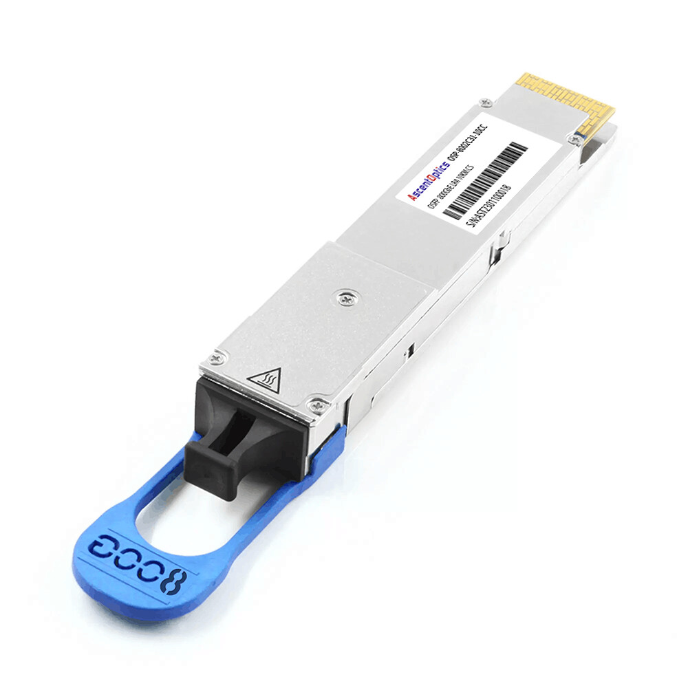
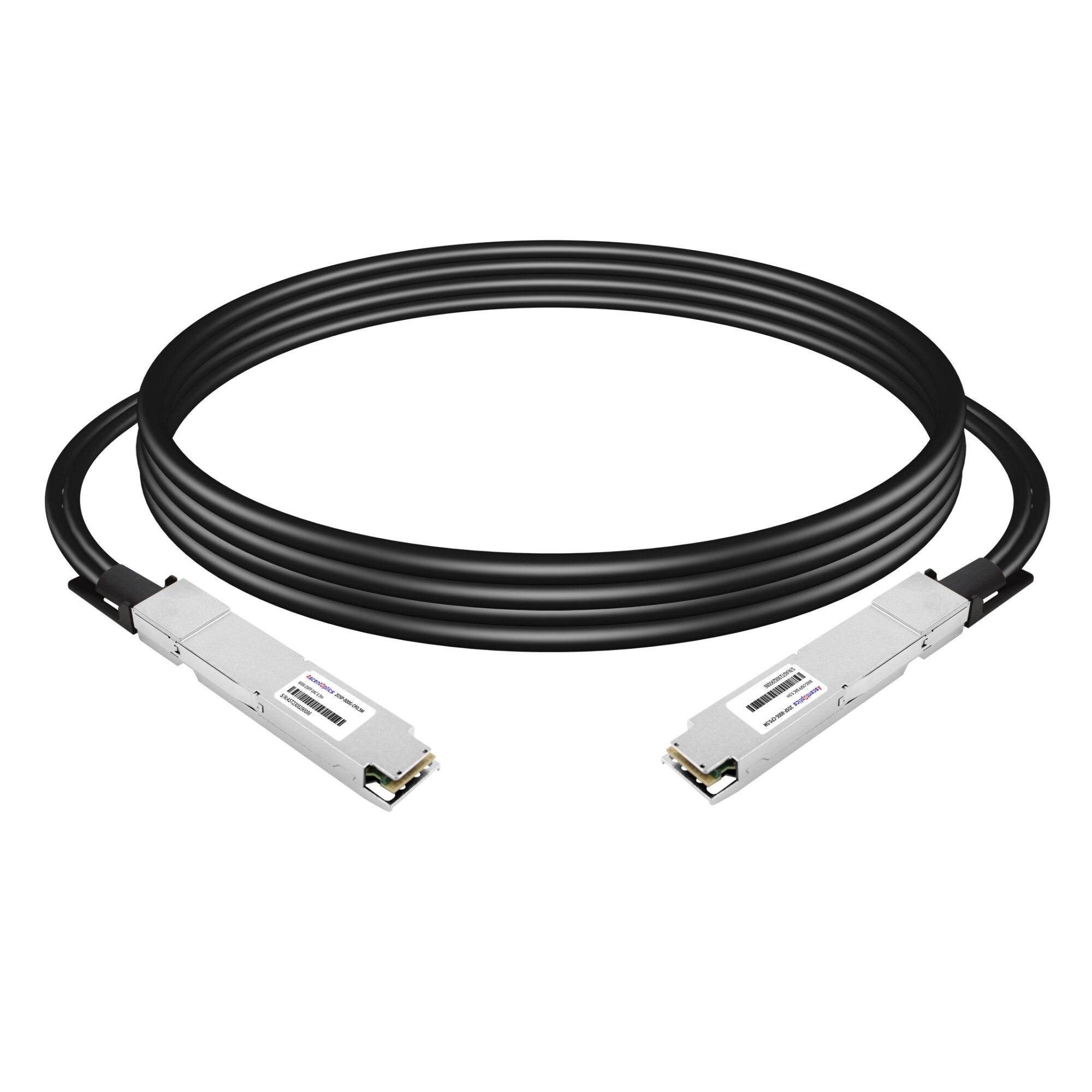
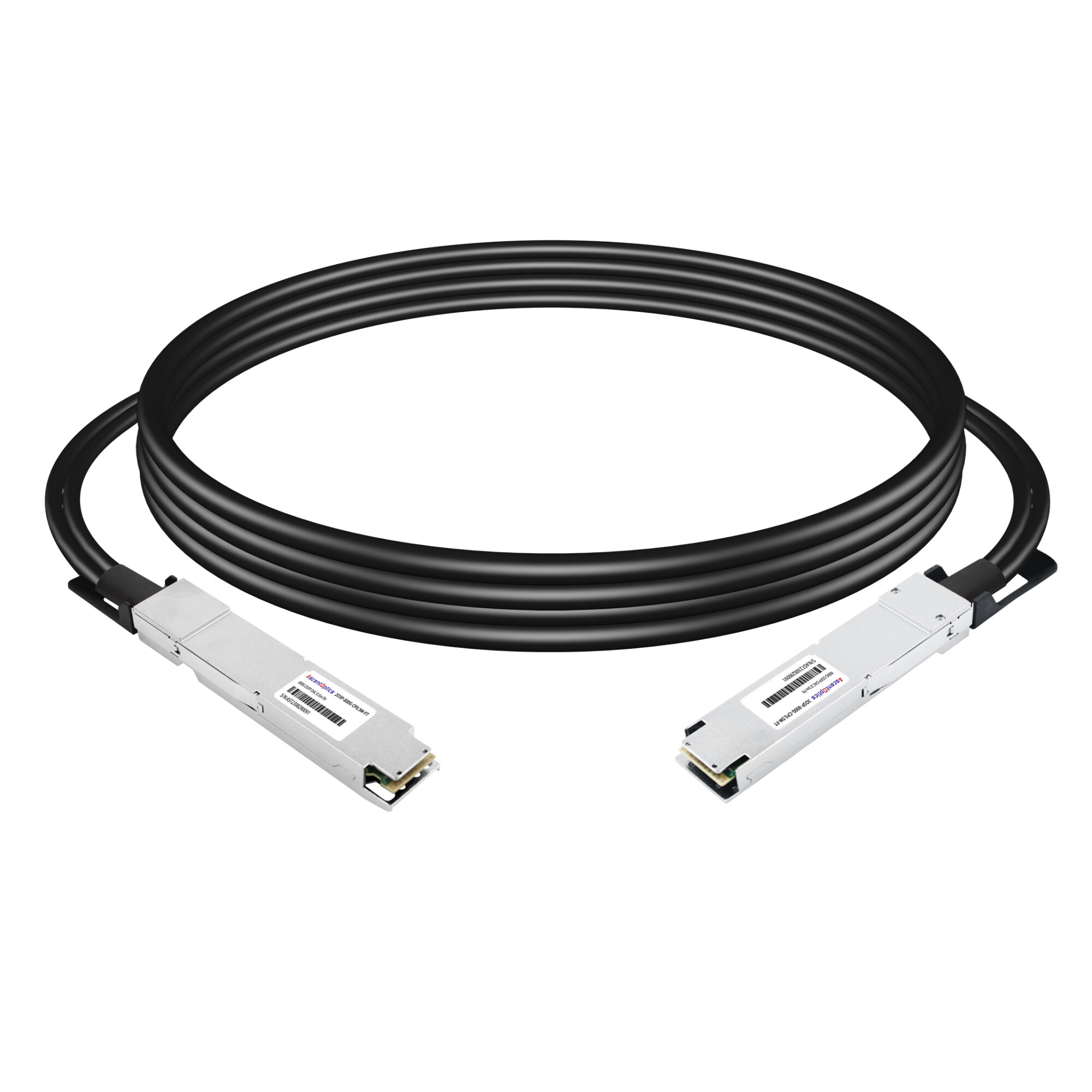
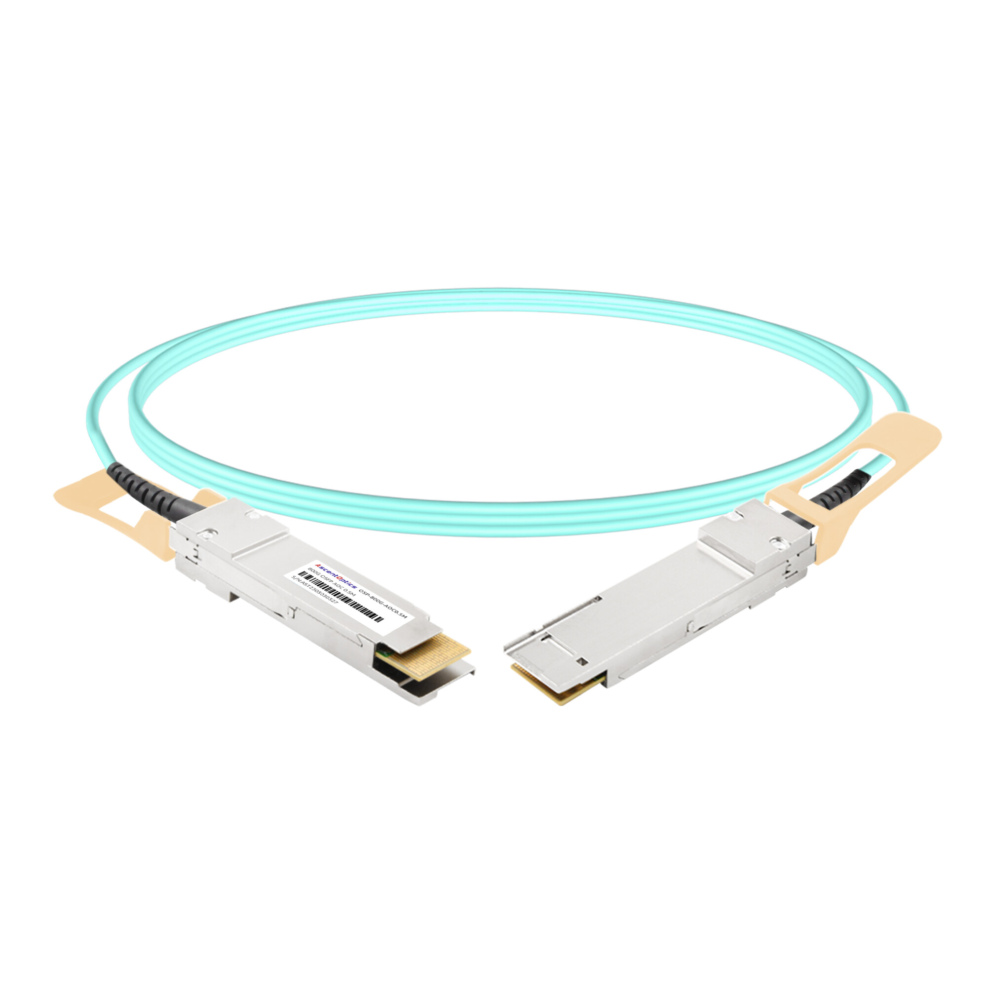
The standardization of 800G optical modules relies on three core specifications. IEEE 802.3df (released in 2024) defines the MAC parameters and physical layer specifications for 800Gb/s Ethernet, covering various transmission media such as copper cables, multimode fiber, and single-mode fiber. OIF’s 800ZR/800LR implementation agreements target coherent optical modules, enabling interoperability for DWDM links exceeding 80 km and short-reach links of 10 km. CMIS (Common Management Interface Specification) serves as a unified management protocol, ensuring interoperability between modules and switches regarding initialization, monitoring, and diagnostics.
What Is IEEE 802.3df?
IEEE 802.3df is an important Ethernet standard for 800 Gb/s and related high-speed Ethernet operation. It defines MAC parameters and physical-layer specifications for 400 Gb/s and 800 Gb/s Ethernet.
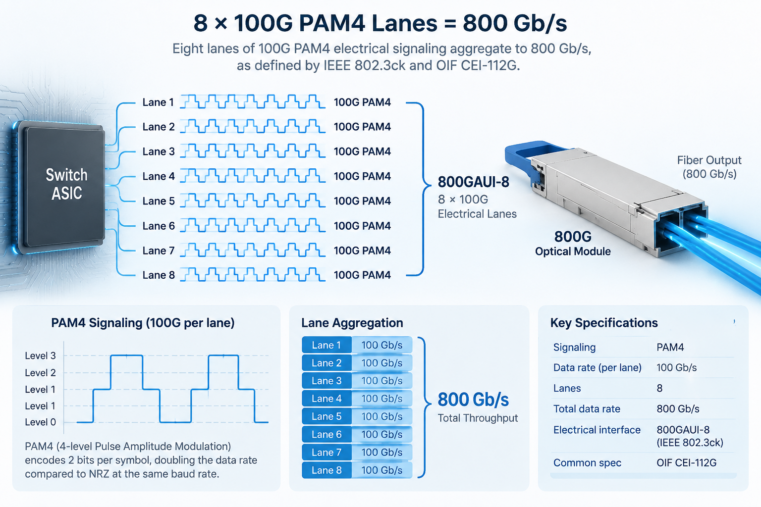
At the 800G level, the technology builds on 100 Gb/s-per-lane signaling. An 800G interface can use eight 100G-class lanes to achieve an aggregate data rate of 800 Gb/s.
The electrical signaling and optical transmission should be viewed as related but separate parts of the standards stack. IEEE 802.3ck provides important specifications for 100 Gb/s electrical lanes, while 802.3df defines the Ethernet PHY and PMD implementations that use these high-speed lanes.
For optical transceiver selection, the PMD specification is particularly important because it determines the intended transmission medium, reach, and optical architecture.
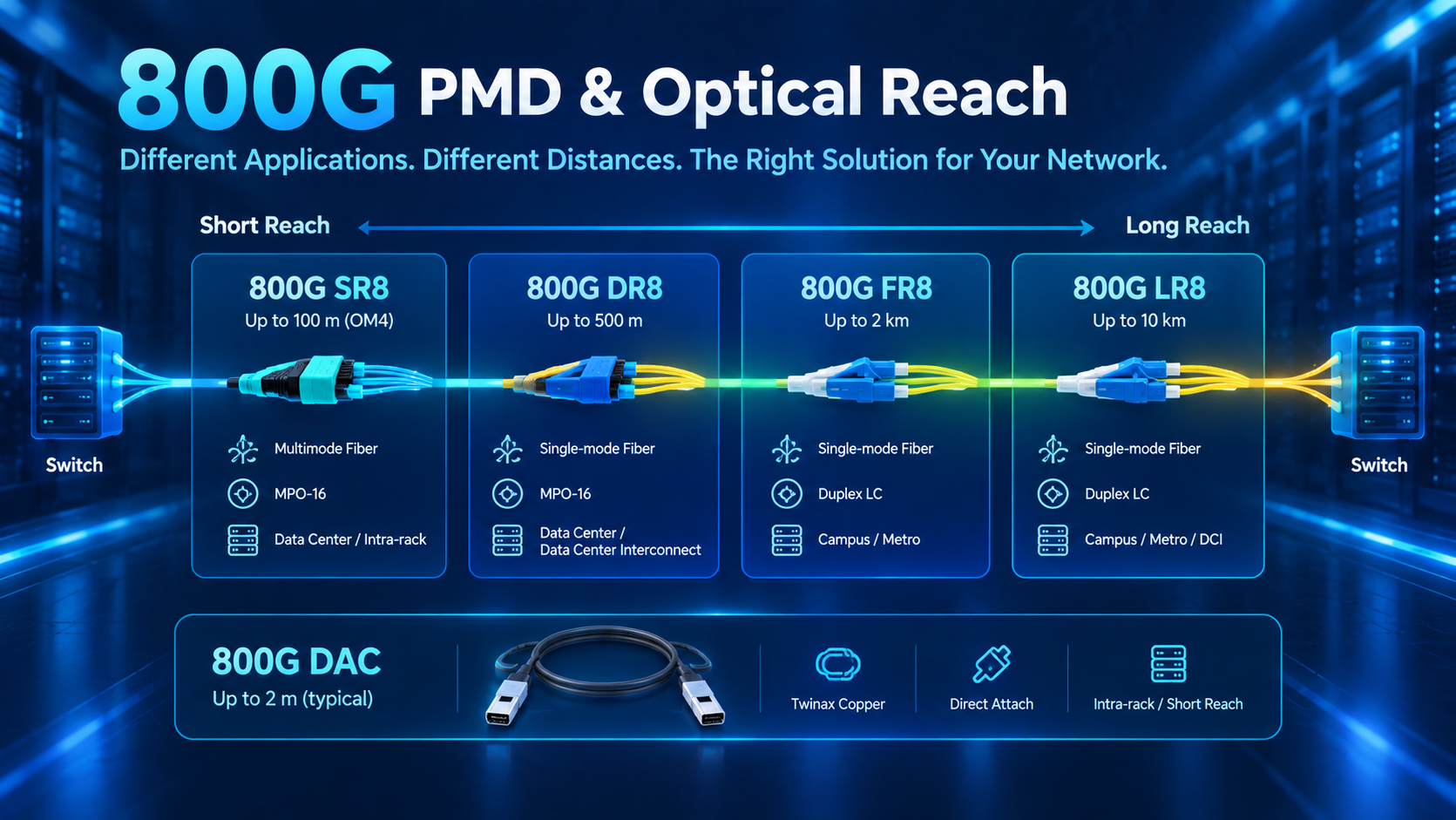
800G Ethernet PMDs and Reach
Different 800G implementations are designed for different network distances and fiber types. Short-reach multimode solutions are commonly used inside data centers, while single-mode solutions support longer links.
| 800G Solution |
Typical Reach |
Fiber / Medium |
Common Connector |
| 800G SR8-class |
Up to 100 m on OM4 |
Multimode fiber |
MPO-16 |
| 800G DR8 |
Up to 500 m |
Single-mode fiber |
MPO-16 |
| 800G FR-class |
Up to around 2 km |
Single-mode fiber |
Duplex LC |
| 800G LR-class |
Up to around 10 km |
Single-mode fiber |
Duplex LC |
| 800G DAC-class |
Short in-rack links |
Twinax copper |
Direct attach |
Actual reach depends on the specific PMD, fiber grade, optical budget, connector loss, and system implementation. Therefore, the product datasheet should always be checked before applying a nominal distance to a specific deployment.
For AI and high-performance data center networks, SR8 and DR8-class solutions are particularly relevant because they support high-density connections between switches, servers, and GPU systems.
The 800G Standards Stack: Who Governs What?
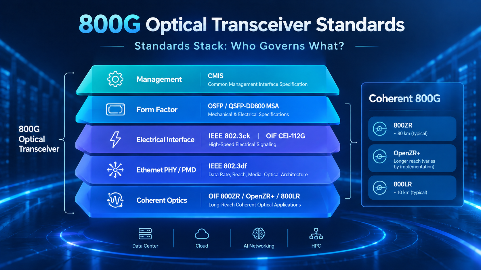
A common mistake is treating “800G” as a single standard. In practice, several specifications define different parts of the system.
| Layer |
What It Defines |
Main Specification / Organization |
| Ethernet PHY / PMD |
Data rate, PHY architecture, reach and media |
IEEE 802.3df |
| Electrical Interface |
High-speed host electrical signaling |
IEEE 802.3ck, OIF CEI-112G |
| Form Factor |
Module size, mechanical interface and pin arrangement |
OSFP MSA, QSFP-DD MSA |
| Management |
Monitoring, diagnostics and module control |
CMIS |
| Coherent Optical |
Long-reach optical implementation agreements |
OIF |
These layers are complementary rather than interchangeable.
For example, IEEE 802.3df compliance does not automatically mean that an optical module will work in every 800G switch. The host port must support the corresponding electrical interface, form factor, management behavior, coding, and optical application.
Physical Layer: OSFP and QSFP-DD800 MSAs
IEEE does not define the mechanical form factor of an optical transceiver. Instead, industry Multi-Source Agreements (MSAs) define the mechanical and electrical characteristics required for compatible modules and host ports.
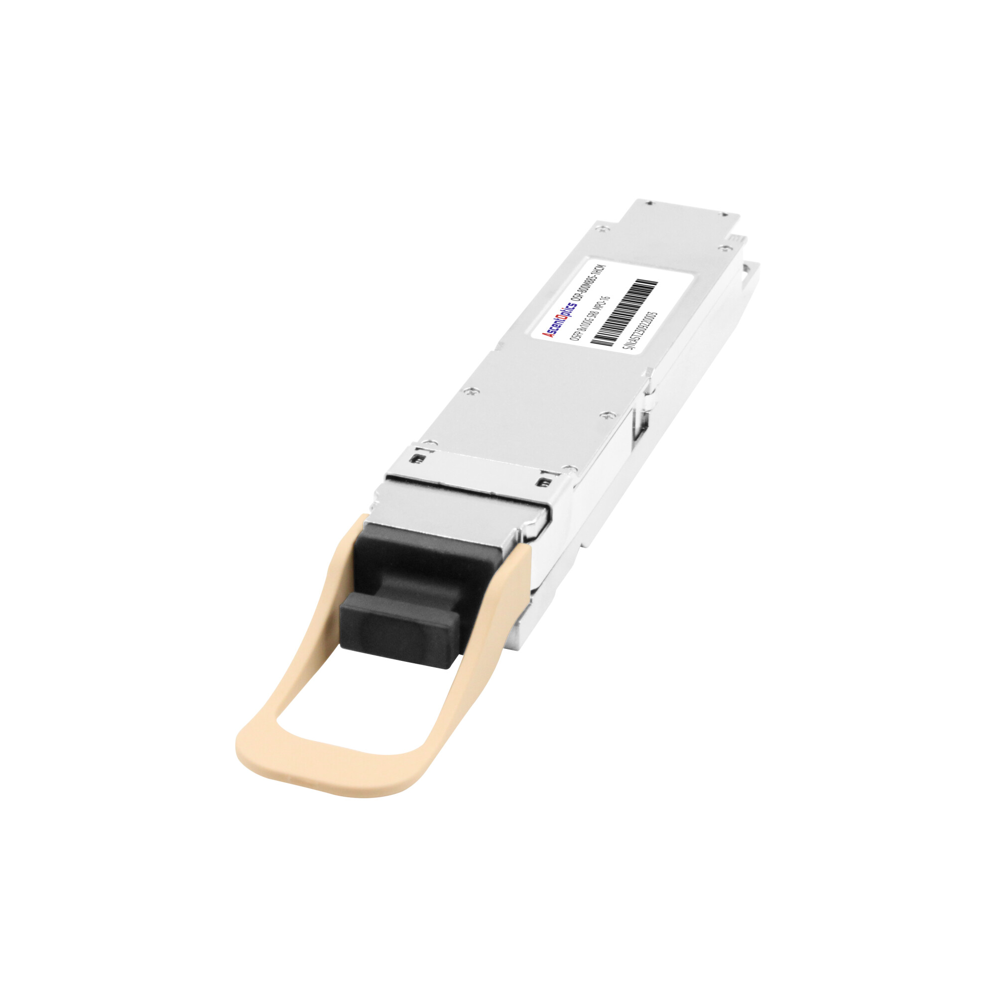
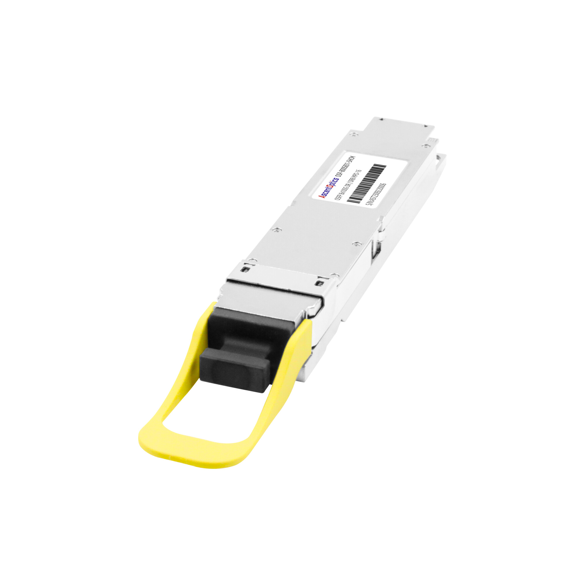
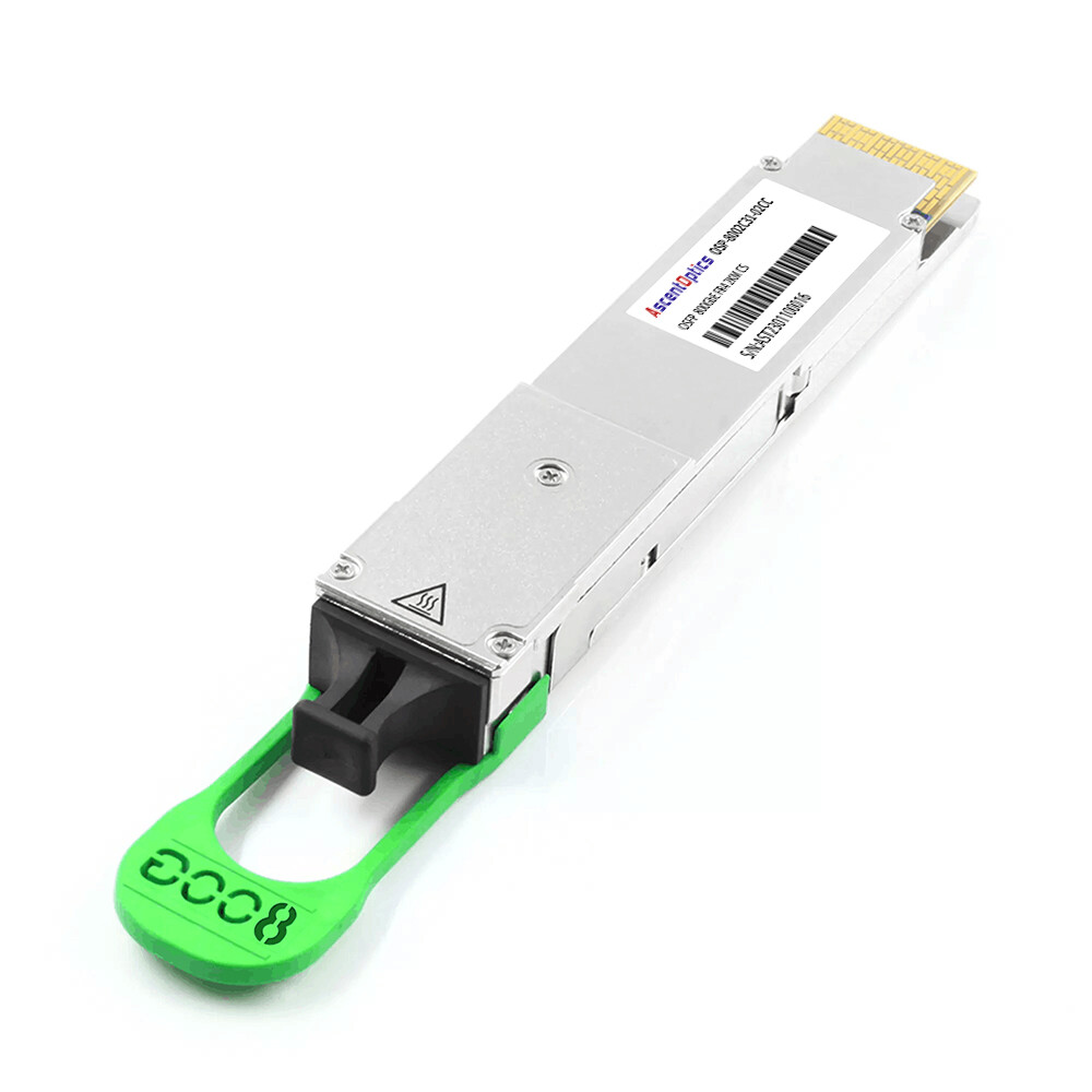
Two important form-factor families for 800G applications are OSFP and QSFP-DD800.
QSFP-DD800 extends the QSFP-DD architecture to support eight high-speed electrical lanes and is designed to maintain compatibility with the broader QSFP ecosystem where applicable.
OSFP uses a larger form factor and provides greater thermal and electrical headroom for high-power optical applications. It is widely used in high-performance networking and AI infrastructure.
An important point is that OSFP and QSFP-DD800 are physically different form factors. An OSFP module cannot simply be inserted into a QSFP-DD800 port, and vice versa.
Therefore, form-factor compatibility should be checked before considering optical parameters.
Electrical Layer: IEEE 802.3ck and OIF CEI-112G
The electrical interface between a switch ASIC, network adapter, or other host device and an optical module is another important part of the 800G architecture.
IEEE 802.3ck defines high-speed electrical signaling at the 100 Gb/s-per-lane level. These technologies provide an important foundation for 800G interfaces based on multiple 100G-class lanes.
The OIF CEI-112G family also addresses high-speed electrical interfaces using PAM4 signaling. The “112G” designation refers to the approximate signaling rate of the electrical lane rather than an 112 Gb/s Ethernet payload.
This distinction is important because a 100G-class Ethernet lane can use a higher raw signaling rate to accommodate encoding and FEC overhead.
In practical 800G systems, the host electrical interface, module electrical design, gearbox or DSP architecture, and FEC implementation all affect interoperability and link performance.
OIF Standards for 800G: CEI-112G, 800ZR and 800LR
The Optical Internetworking Forum (OIF) complements IEEE Ethernet standards by defining implementation agreements for high-speed electrical and coherent optical technologies.
CEI-112G
OIF CEI-112G specifications address electrical interfaces for approximately 112 Gb/s signaling and are widely relevant to 100G-class electrical lanes used in high-speed networking equipment.
These specifications are particularly important when designing the electrical path between host ASICs and pluggable optical modules.
Coherent 800G: 800ZR, OpenZR+ and 800LR
Not every 800G application uses short-reach direct-detect optics.
For data center interconnect and metro networks, coherent pluggable optics can provide significantly longer transmission distances.
800ZR is designed for high-capacity coherent transmission over approximately 80 km-class links, depending on the network design and operating conditions.
OpenZR+ extends the coherent pluggable concept toward longer and more flexible optical links, with achievable reach depending on the implementation, channel spacing, amplification, fiber characteristics, and optical budget.
800LR targets shorter coherent links, such as approximately 10 km-class applications.
Coherent 800G modules also require additional management considerations, including coherent-specific management extensions such as C-CMIS.
CMIS: The Management Interface for 800G Modules
CMIS, or the Common Management Interface Specification, defines a standardized management framework for pluggable optical modules.
Many modern 800G transceivers use CMIS to allow the host system to identify, configure, monitor, and diagnose the module.
Typical management functions include:
- •Module identification and vendor information
- •Temperature and voltage monitoring
- •Transmit and receive optical power monitoring
- •Alarm and warning reporting
- •Digital diagnostics
- •Module configuration and application selection
- •Firmware-related management functions, depending on the CMIS version and implementation
The exact CMIS version supported by an 800G module can vary. Therefore, network operators should check both the module documentation and the switch or NIC documentation when evaluating interoperability.
For coherent modules, C-CMIS extends the management model to address additional requirements associated with coherent optical technology.
Standards Compliance vs. Real-World Compatibility
One of the most important points for 800G deployment is that standards compliance does not automatically guarantee platform compatibility.
A module may comply with the relevant Ethernet standard, MSA, and management specification but still be rejected by a particular switch or network operating system.
This can happen because equipment vendors may apply additional requirements to module identification, EEPROM or memory-map fields, application codes, supported modes, FEC settings, firmware behavior, or vendor-specific validation.
For this reason, 800G transceiver selection should consider both standards compliance and platform compatibility.
Before deployment, verify:
- •Form factor— OSFP, QSFP-DD800, or another supported architecture.
- •Host electrical interface— supported lane speed and electrical signaling.
- •Optical application— SR8, DR8, FR/LR-class, coherent, or another implementation.
- •Fiber and connector— MMF or SMF, MPO-16, duplex LC, or another connector type.
- •Management interface— supported CMIS version and required features.
- •FEC and operating mode— whether the host and module support the required configuration.
- •Platform coding and validation— whether the module is supported by the target switch, NIC, or other host equipment.
This is particularly important for multi-vendor networks where modules and switches come from different manufacturers.
From 800G to 1.6T: The Standards Roadmap
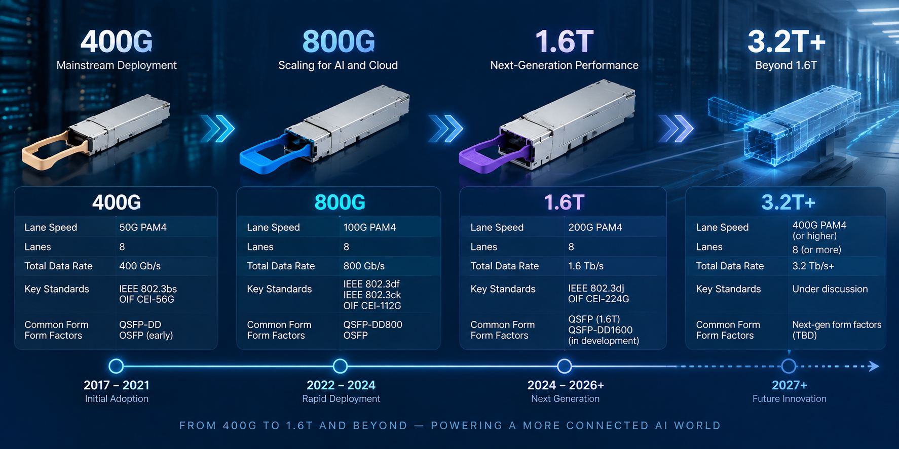
The transition from 800G to 1.6T is closely connected to the move from 100G-class lanes toward 200G-class lanes.
IEEE 802.3dj is being developed for next-generation Ethernet operating at up to 1.6 Tb/s and includes technologies based on 200 Gb/s-per-lane signaling.
On the electrical side, OIF CEI-224G addresses approximately 224 Gb/s signaling, providing an electrical technology path for 200G-class lanes.
The industry is also developing higher-density form factors, including technologies such as OSFP-XD and QSFP-DD 1.6T-class architectures, to accommodate the increased electrical bandwidth and power requirements.
The key change is the lane-speed transition:
- •800G → 8 × 100G-class lanes
- •1.6T → 8 × 200G-class lanes or higher-density lane architectures
This transition will affect optical engines, DSPs, host electrical interfaces, thermal design, connectors, and module form factors.
For organizations planning large-scale AI or data center upgrades, understanding the lane-speed roadmap can help avoid short-term infrastructure decisions that limit future migration options.
How to Evaluate 800G Optical Transceiver Standards
When purchasing or deploying an 800G optical transceiver, checking the data rate alone is not enough.
A practical evaluation should start with the following questions:
- 1. Which Ethernet PHY or PMD does the module support?
Confirm the exact application instead of relying only on the “800G” label.
- 2. Which form factor does the host support?
Check whether the platform accepts OSFP, QSFP-DD800, or another form factor.
- 3. What electrical interface is required?
Verify lane count, lane speed, signaling technology, and host-side requirements.
- 4. What is the actual optical reach?
Consider fiber type, connector loss, optical budget, and the specific module implementation.
- 5. Which management specification is supported?
Check CMIS version and the management features supported by both ends.
- 6. Is the module validated for the target platform?
Platform coding and vendor validation can be just as important as standards compliance.
Conclusion
800G optical transceiver technology is based on a standards stack rather than a single specification.
IEEE 802.3df defines important Ethernet PHY and PMD specifications for 800G operation. IEEE 802.3ck and OIF CEI-112G contribute to the high-speed electrical interface technology. OSFP and QSFP-DD MSAs define the physical form factor, while CMIS provides a standardized management framework for many pluggable modules. OIF coherent implementation agreements address longer-reach 800G optical applications.
For network operators, the practical approach is to evaluate these specifications together. Check the Ethernet application, electrical interface, form factor, optical reach, management interface, FEC configuration, and platform compatibility before selecting an 800G optical transceiver.
As 200G-per-lane technologies and 1.6T Ethernet continue to develop, understanding the 800G standards stack also provides a useful foundation for planning the next generation of AI and data center networks.
Post Views: 95