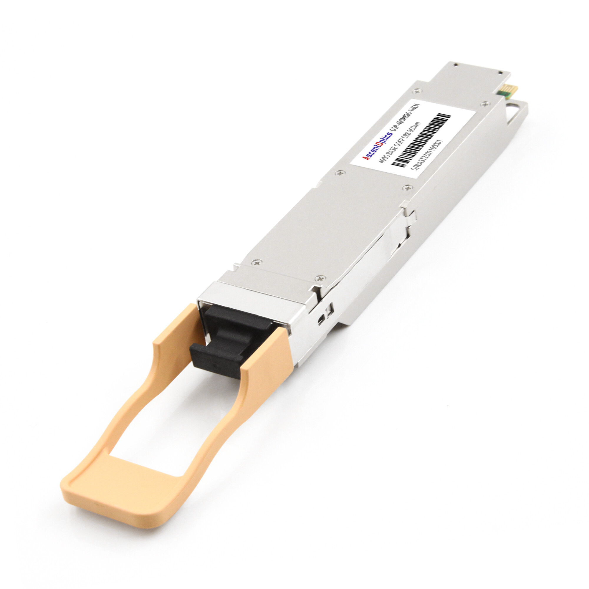
At hundreds or thousands of GPUs, the network is no longer simply infrastructure around the compute system. It becomes part of the compute system itself.
Teams planning an AI cluster often spend most of their time comparing GPUs, memory capacity, and storage performance, while treating the scale-out network as a secondary decision. That can be expensive. Distributed training relies heavily on collective communication, and when gradient synchronization or tensor exchange stalls, GPUs remain underutilized while the training job waits.
For tightly coupled GPU workloads, network bandwidth, latency, congestion behavior, topology, and GPU-to-NIC locality can therefore have a direct impact on overall cluster efficiency.
Why GPU Clusters Use InfiniBand
InfiniBand is a lossless, high-throughput interconnect built for the exact traffic pattern that breaks ordinary Ethernet: thousands of GPUs exchanging synchronized gradient updates at the same instant.
Large-language-model training is not a gentle stream of requests. It runs collective operations, chiefly AllReduce, where every GPU must share its gradients with every other GPU before the next iteration can begin. A single slow link holds up the entire job. InfiniBand solves this with credit-based flow control, which never drops packets, and hardware-level Remote Direct Memory Access (RDMA) that moves data straight into GPU memory without touching the CPU.
The numbers tell the story. InfiniBand delivers roughly 0.6 microseconds of end-to-end latency and about 95% bandwidth efficiency. A well-tuned Ethernet fabric with RDMA over Converged Ethernet (RoCEv2) lands closer to 1.2 microseconds and 85 to 92% efficiency, and it can collapse under the congestion spikes that all-to-all traffic creates.
The practical threshold most practitioners cite is around 256 GPUs. Below that, Ethernet is usually fine and cheaper. Above it, InfiniBand’s predictable latency and lossless behavior justify the premium. OpenAI reportedly cut GPT-4 training time by about 40% when it moved to InfiniBand, and InfiniBand NDR sustained roughly 92% scaling efficiency on a 512-GPU LLaMA-405B run.
The honest counterpoint is cost. Meta found InfiniBand delivered about 15% better performance but at 2.3 times the total cost of ownership at 600,000-GPU scale, and it standardized on Ethernet. The decision is real and workload-dependent, which is exactly why the design process matters more than the brand on the box.
InfiniBand Speed Generations: HDR, NDR, and XDR
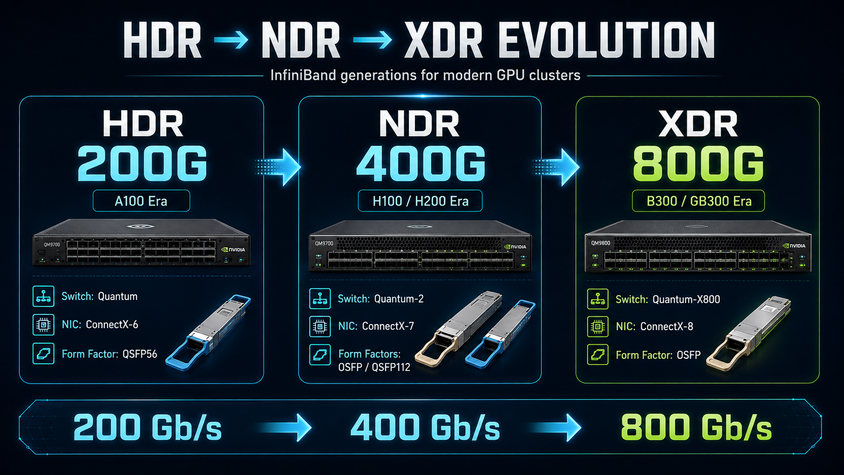
Every InfiniBand GPU cluster is built on one of three active generations. Each lines up with a specific era of NVIDIA accelerators, and each pulls a different transceiver form factor.
| Generation |
Maximum Port Rate |
Common GPU Platforms |
Switch Platform |
Typical Adapter |
Typical Interconnect Form Factors |
| HDR |
200 Gb/s |
A100-generation systems |
NVIDIA Quantum |
ConnectX-6 |
QSFP56 |
| NDR |
400 Gb/s |
H100, H200 and many Blackwell deployments |
NVIDIA Quantum-2 |
ConnectX-7 |
Twin-port OSFP on Quantum-2; OSFP or QSFP112 depending on server/NIC |
| XDR |
800 Gb/s |
B300 / GB300 and new ConnectX-8 platforms |
NVIDIA Quantum-X800 |
ConnectX-8 SuperNIC |
Twin-port OSFP on switch; single-port OSFP on 800G adapter/server |
These mappings describe common deployment patterns rather than strict GPU-to-network-generation requirements.
HDR brought 200 Gb/s InfiniBand into the A100 generation. NDR doubled that to 400 Gb/s and is widely used with H100 and H200 systems. NVIDIA Quantum-2 switches use twin-port OSFP cages in which one physical OSFP interface can expose two independent 400 Gb/s NDR ports. ConnectX-7 adapters, however, are available in both OSFP and QSFP112 implementations, so the server side should always be specified according to the exact adapter or system rather than assuming QSFP112.
DGX H100/H200 is a good example. It contains eight 400 Gb/s ConnectX-7 cluster-network interfaces, but those interfaces are presented externally through four OSFP cages, with each cage carrying two 400 Gb/s links.
XDR moves the scale-out fabric to 800 Gb/s per InfiniBand port. ConnectX-8 C8180 supports a native 800 Gb/s XDR InfiniBand port through OSFP, while Quantum-X800 systems use high-density twin-port OSFP interfaces.
A DGX B300, for example, provides eight 800 Gb/s cluster-network OSFP connections to eight ConnectX-8 devices—one high-bandwidth network interface for each of its eight B300 GPUs.
Designing the Fabric: InfiniBand Topology for GPU Clusters
Topology determines how effectively the available port bandwidth can be used.
Fat-Tree / Clos
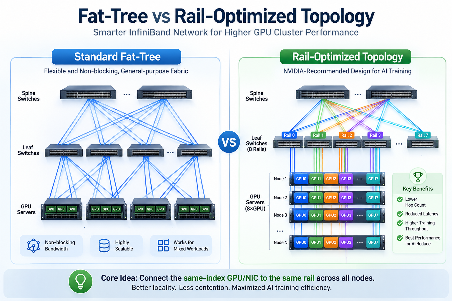
A non-blocking fat-tree or Clos network provides equal aggregate bandwidth between the endpoint-facing and uplink-facing sides of the fabric.
In a two-tier leaf-spine design, compute nodes connect to leaf switches while the leaves connect to the spine layer. A 1:1 non-blocking design provides full bisection bandwidth, while a cost-optimized design may intentionally use oversubscription.
Fat-tree is flexible, well understood, and suitable for mixed workloads. Its main disadvantages are switch count, cable count, optical power, and cost as the cluster grows.
Rail-Optimized Topology
Rail optimization is particularly important in multi-GPU AI systems.
Instead of randomly connecting GPU NICs to leaf switches, the same NIC or GPU position across multiple servers is connected to the same network rail. For example, NIC 0 from a group of eight-GPU servers may connect to Rail 0, NIC 1 to Rail 1, and so on.
This arrangement allows communication libraries such as NCCL to exploit both the NVLink/NVSwitch fabric inside each server and the corresponding network rail between servers. It can reduce unnecessary traversal between rails, lower contention, and improve locality for collective operations.
NVIDIA describes rail-optimized topology as a way to maximize AllReduce performance and minimize interference between network flows. It is now a standard design principle in many large GPU fabrics.
Rail optimization should not, however, be interpreted as meaning that every packet stays on a single leaf switch. Depending on cluster size and destination, traffic may still traverse the spine or higher network tiers.
Dragonfly+ for Large Fabrics
Dragonfly+ is another InfiniBand topology supported by NVIDIA for very large systems.
Instead of building an increasingly large conventional fat-tree, Dragonfly+ organizes switches into groups and uses carefully structured global connections between them. This can reduce the number of high-radix switching stages and long-distance links required for very large fabrics.
The choice between fat-tree and Dragonfly+ should therefore be based on cluster scale, switch radix, routing design, locality requirements, cable economics, and failure-domain strategy—not simply whether the cluster spans more than one building.
NVIDIA’s InfiniBand topology tools support both fat-tree and Dragonfly+ architectures.
Bandwidth Budgeting: From GPU to Fabric
Designing a fabric means accounting for bandwidth at every hop so that no link becomes the choke point.
Start with node egress, the 3.2 Tbps of an eight-GPU NDR node. Then budget the GPU-to-switch links, the leaf-to-spine links, and any cross-rail links. The rule is simple: oversubscription anywhere becomes the wall the whole training run leans against.
Two mechanisms make the fabric efficient. GPUDirect RDMA lets a NIC write directly into GPU memory, skipping the CPU and system memory entirely, which is essential at 400G and above. NVLink handles the ultra-fast GPU-to-GPU paths inside a node, while InfiniBand handles node-to-node communication. Knowing which path a collective takes tells you where your real bandwidth pressure sits.
There is a subtle gotcha worth checking before you commit. GPUDirect RDMA only delivers full speed when each GPU shares a PCIe switch with its dedicated NIC, reported as PIX affinity in nvidia-smi topo -m. If it reports SYS, meaning a cross-NUMA path, direct GPU-to-NIC transfers fail and performance can roughly halve.
SHARP in-network computing compounds these gains. Instead of sending all gradient data back to the GPUs to be summed, SHARP-enabled switches perform the reduction in the switch itself. This collapses the round trips from O(log N) down to O(1) and can cut collective traffic by up to 9x on large clusters. It is one of the quiet reasons InfiniBand holds its edge at frontier scale.
The Optical Interconnect Layer
At NDR and XDR speeds, the physical interconnect becomes a major part of the network architecture.
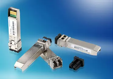
Port form factor, thermal design, optical reach, connector type, fiber polarity, breakout architecture, and switch/NIC compatibility all need to be specified correctly.
NDR: The Two-Ends Problem
NDR is often misunderstood because the physical interface at the two ends of a link is not necessarily identical.
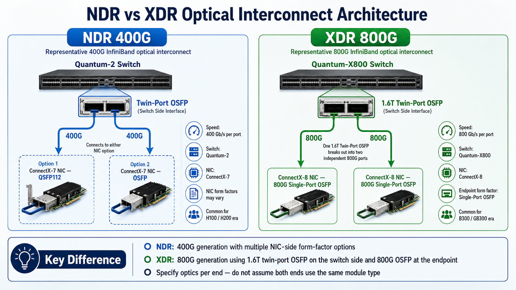
Quantum-2 switches use finned-top twin-port OSFP interfaces capable of carrying two independent 400 Gb/s NDR ports.
The server side depends on the platform.
A standard ConnectX-7 adapter may use either OSFP or QSFP112, while DGX H100/H200 exposes its eight 400G cluster links through four twin-port OSFP interfaces.
This means buyers should specify optics according to the actual equipment at each end rather than applying a universal rule such as:
OSFP switch → QSFP112 NIC
That configuration exists, but it is only one of several supported NDR architectures.
XDR: 800G OSFP Architecture
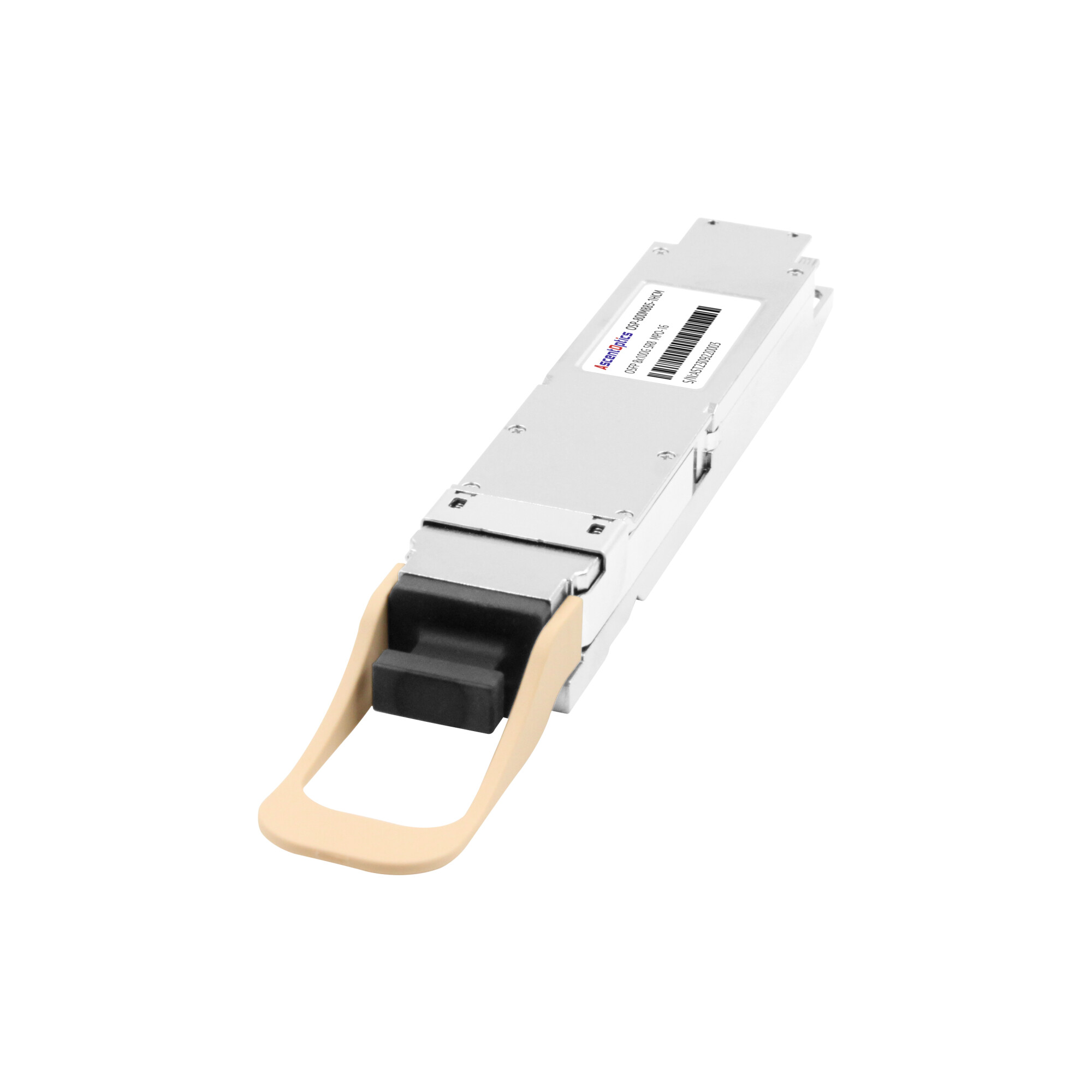
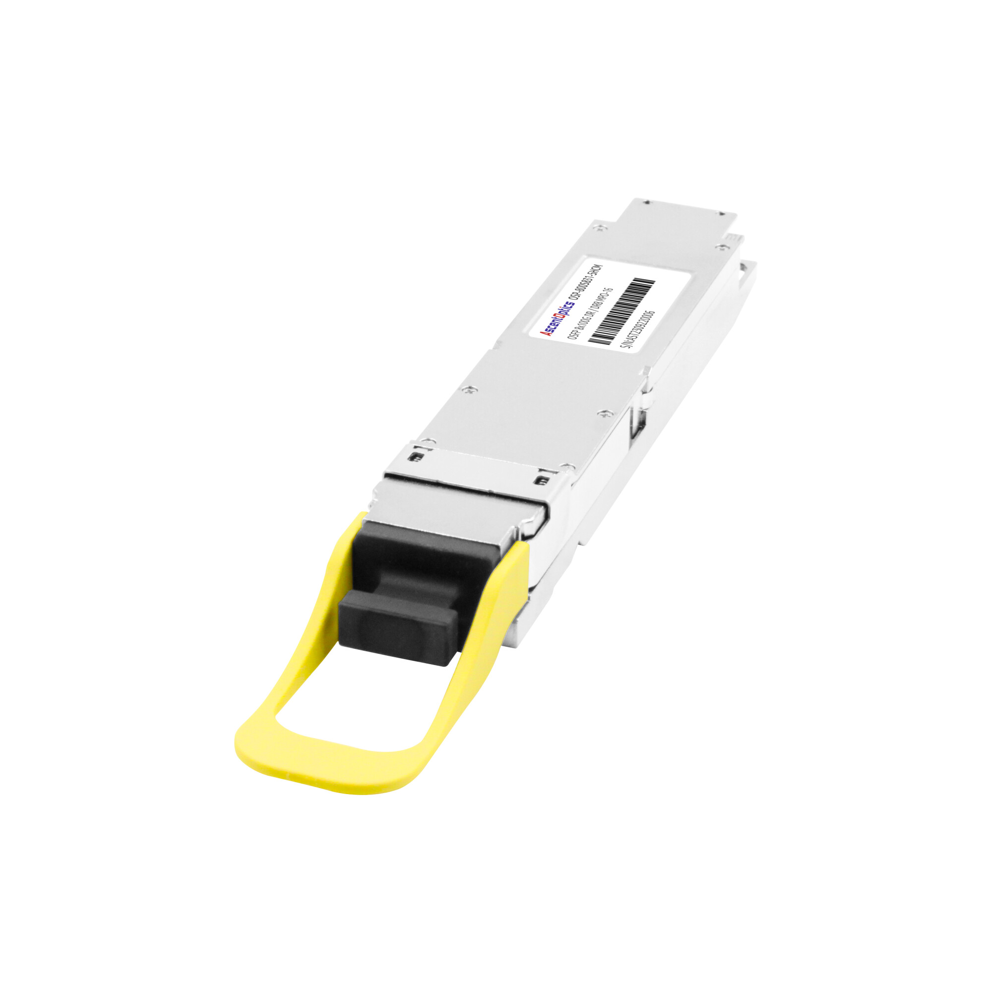
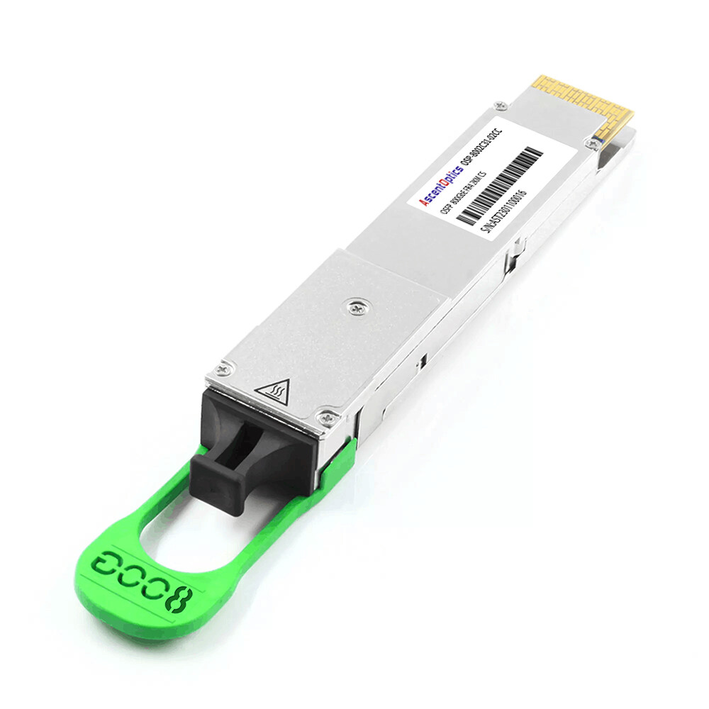
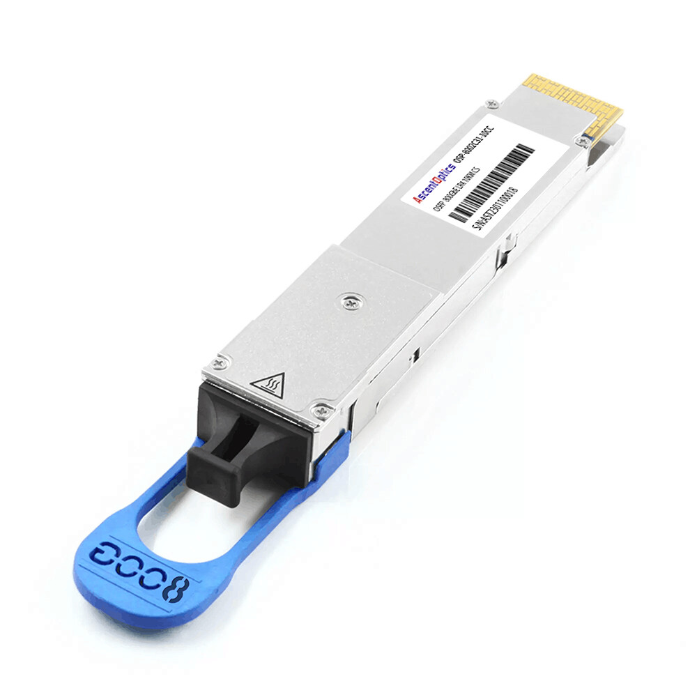
XDR changes the physical layer again. The ConnectX-8 C8180 uses a single OSFP interface for one native 800 Gb/s XDR InfiniBand port.
Quantum-X800 Q3200 and Q3400 switches use twin-port OSFP architecture, allowing one physical OSFP cage to carry two independent 800 Gb/s ports. The Q3200 provides 72 XDR 800G ports across 36 OSFP cages, while the Q3400 provides 144 XDR 800G ports across 72 OSFP cages.
One current NVIDIA optical implementation uses a 1.6 Tb/s twin-port 2×DR4 OSFP transceiver at the Quantum-X800 switch, with each optical half connecting to an 800G DR4 single-port OSFP transceiver at a ConnectX-8 endpoint.
This distinction is essential when building an XDR bill of materials.
DAC, AOC, or Optical Transceivers?
Distance, cable routing, thermal limits, maintainability, and equipment compatibility determine the best medium.
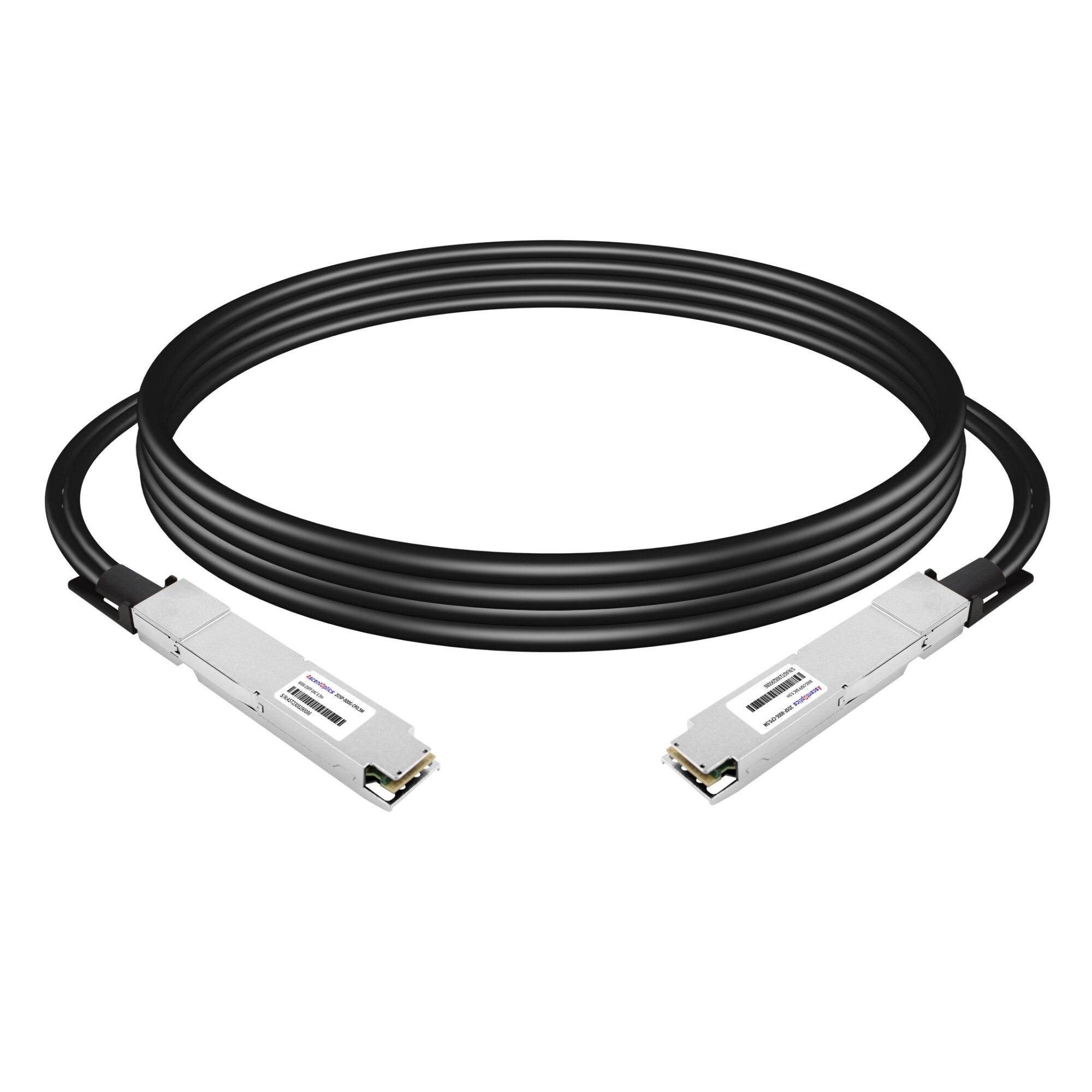
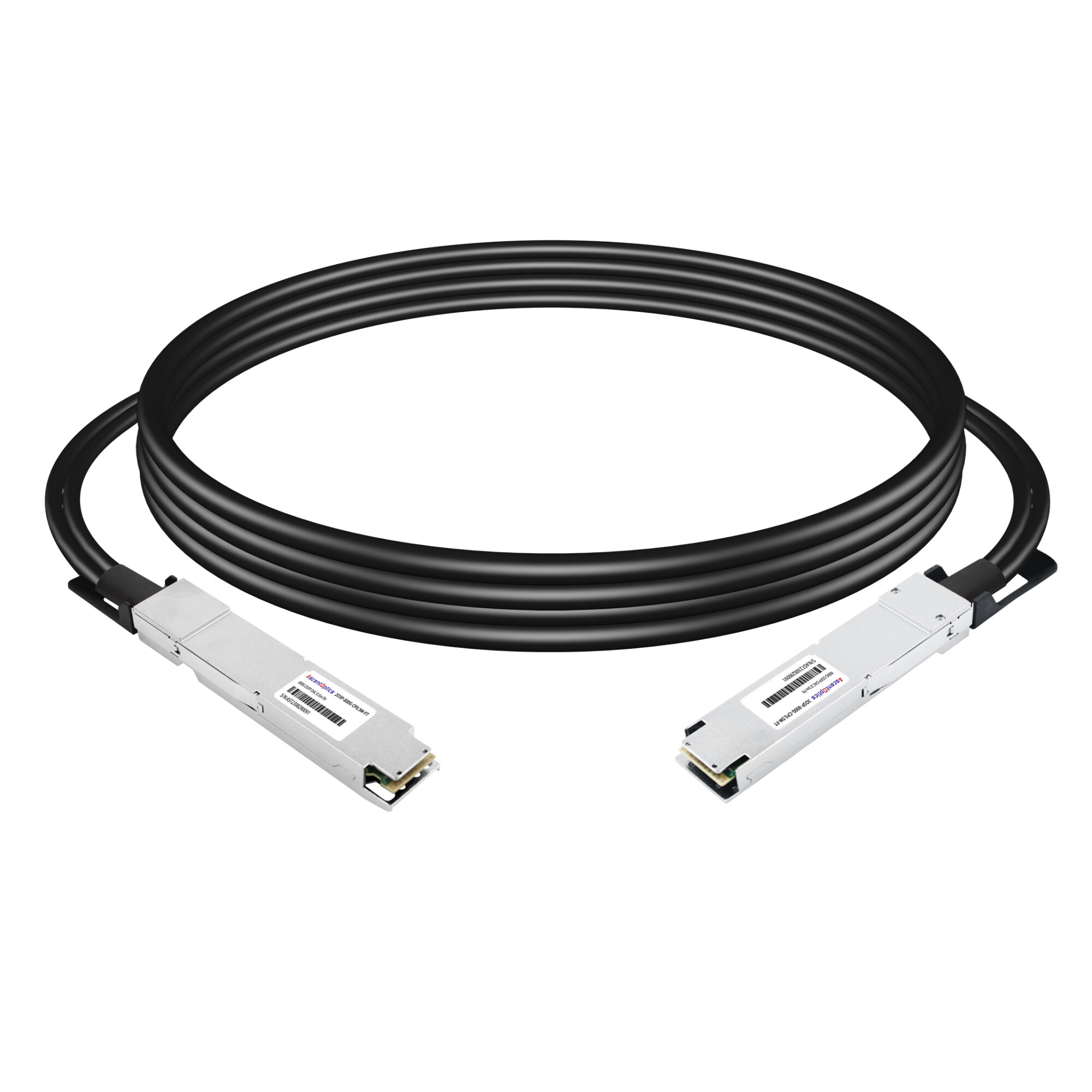
- 1. For very short links, passive copper DACs can provide low power and low cost where the host and cable reach support them.
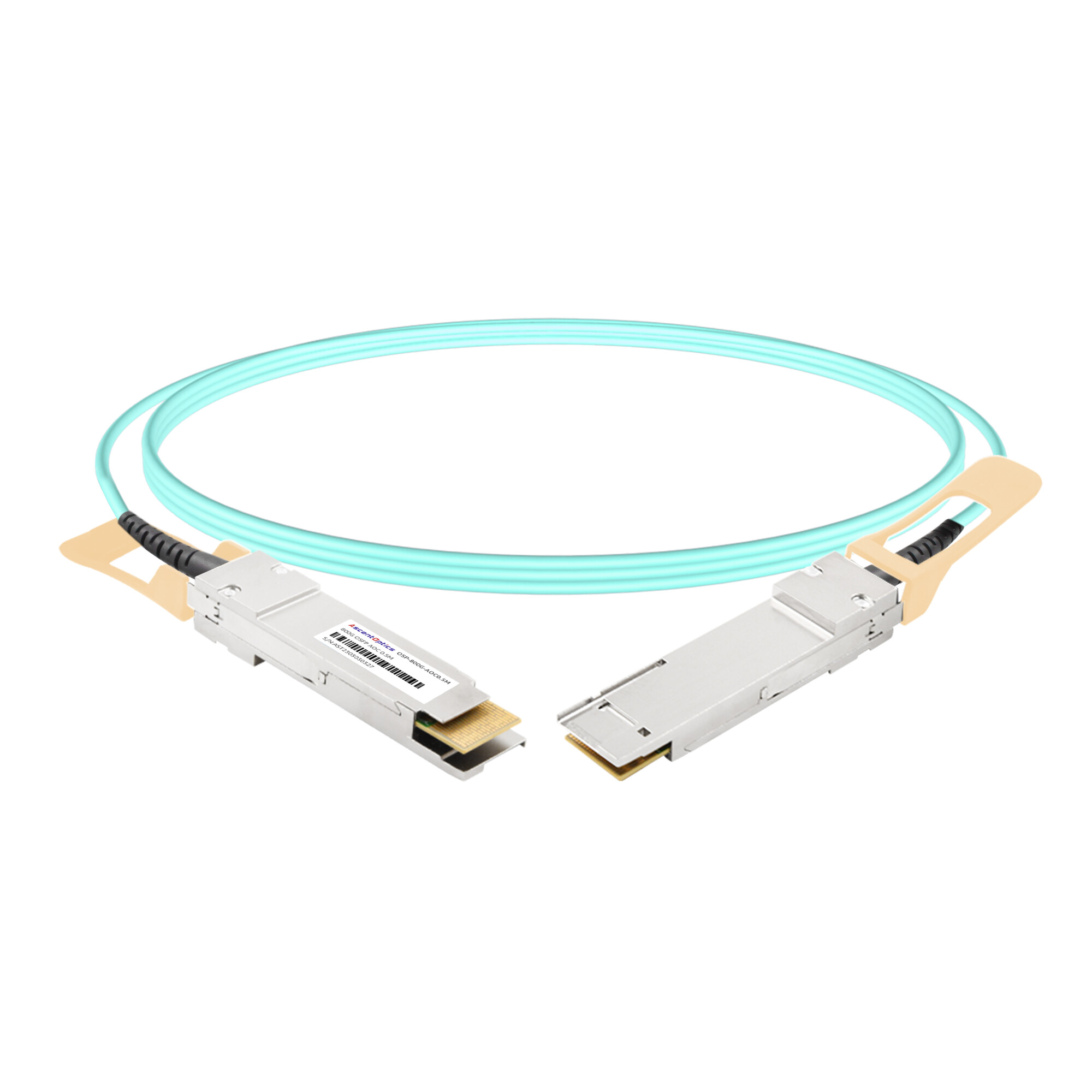
- 2. For short- to medium-distance links, AOCs simplify installation by integrating the optics and fiber into a factory-terminated cable assembly.
- 3. For structured cabling or longer links, pluggable optical transceivers provide greater flexibility and serviceability.
The exact reach must be matched to the network generation and supported transceiver portfolio.
For NDR, NVIDIA’s 400G interconnect portfolio includes short-reach multimode options and single-mode DR4 options up to 500 meters, while selected twin-port 2×FR4 solutions extend to 2 kilometers. These should not be confused with every 400GbE FR4 or LR4 product on the Ethernet market.
For XDR, NVIDIA currently offers 800G single-port DR4 and 1.6T twin-port 2×DR4 optical architectures for up to 500-meter single-mode links.
Longer-reach requirements should therefore be qualified against the exact switch, adapter, protocol, transceiver firmware, and supported-cable matrix rather than selected by reach alone.
Power and Thermal Design
At 400G and especially 800G, optics are a meaningful part of the network power budget.
High-density twin-port OSFP modules can dissipate significantly more power than older QSFP-class optics, which is why Quantum-2 and Quantum-X800 air-cooled switches use integrated heatsink or finned-top transceiver designs.
The switch architecture itself must also be considered.
Quantum-X800 Q3200, for example, has a typical system power figure of 862 W with passive cables, but its maximum system power can reach several kilowatts when active interconnects are installed.
At cluster scale, the optical layer therefore affects electrical capacity, cooling, rack density, cable management, and operating cost.
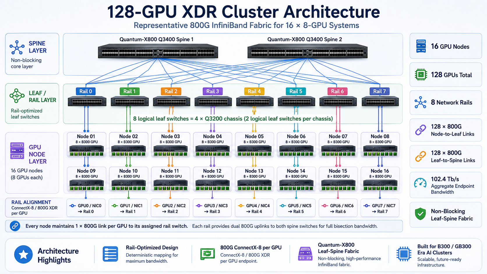
A Representative 128-GPU XDR Cluster
Consider a 128-GPU cluster built from sixteen DGX B300-class eight-GPU systems.
Each system contains eight B300 GPUs and eight 800 Gb/s ConnectX-8 cluster-network interfaces, giving the cluster:
128 GPUs × 800 Gb/s = 102.4 Tb/s of aggregate endpoint line rate.
A representative rail-optimized, non-blocking two-tier XDR design could use the following architecture.
| Component |
Representative Quantity |
Function |
| DGX B300-class 8-GPU nodes |
16 |
128 B300 GPUs total |
| ConnectX-8 800G interfaces |
128 |
One cluster-network interface per GPU |
| Quantum-X800 Q3200 chassis |
4 |
Eight independent 36-port logical leaf switches, two per chassis |
| Quantum-X800 Q3400 spine switches |
2 |
High-radix spine layer |
| Node-to-leaf XDR links |
128 |
800G per GPU/NIC |
| Leaf-to-spine XDR links |
128 |
Provides 1:1 aggregate leaf uplink bandwidth |
The Q3200 contains two independent 36-port XDR switches in one 2U chassis. In this example, each logical leaf serves one GPU rail:
- 16 × 800G downlinks to the same-index GPU/NIC across sixteen servers
- 16 × 800G uplinks toward the two Q3400 spine switches
- 32 of the available 36 XDR ports used
Across eight rails, four Q3200 chassis provide eight logical leaf switches.
Each leaf can then connect eight 800G links to Spine 1 and eight to Spine 2. Each Q3400 therefore consumes 64 of its available 144 XDR ports. This preserves equal aggregate endpoint and uplink bandwidth at the leaf layer while maintaining the rail structure.
Example Optical BOM
If all 800G links use DR4 optics rather than DAC or AOC:
| Optical Component |
Approximate Quantity |
| 800G single-port OSFP DR4 at ConnectX-8 endpoints |
128 |
| 1.6T twin-port OSFP 2×DR4 for leaf downlinks |
64 |
| 1.6T twin-port OSFP 2×DR4 for leaf uplinks |
64 |
| 1.6T twin-port OSFP 2×DR4 at spine switches |
64 |
| 800G optical fiber links |
256 |
That means approximately 192 twin-port switch-side OSFP optical modules plus 128 single-port endpoint OSFP modules, before operational spares.
This is a representative engineering example rather than a universal purchase list. Actual quantities can change with cable reach, DAC/AOC usage, port pairing, redundancy strategy, switch choice, spare policy, storage traffic, management networks, and future-expansion capacity.
Scaling Beyond 1,000 GPUs
As GPU counts increase, the same design principles still apply, but locality, routing, optical power, failure domains, and topology become increasingly important.
Large AI clusters are no longer exclusively InfiniBand.
xAI’s Colossus demonstrates the scale that modern GPU infrastructure can reach, with its published system growing to approximately 200,000 H100 GPUs.
At the same time, large-scale Ethernet AI fabrics are increasingly common. This means the industry should no longer treat the choice as simply:
InfiniBand for large clusters, Ethernet for small clusters.
The real decision is between different fabric architectures, transport implementations, congestion-control systems, operational models, and economics.
InfiniBand remains particularly attractive where predictable RDMA performance, integrated congestion management, SHARP, and a validated NVIDIA end-to-end ecosystem are priorities.
RoCE Ethernet is attractive where Ethernet operational familiarity, multi-vendor ecosystems, converged infrastructure, or specific cloud architectures are more important.
InfiniBand in the Cloud
Cloud networking also needs to be described carefully because not every high-performance GPU cloud uses InfiniBand.
Microsoft Azure ND H100 v5 provides eight 400 Gb/s NVIDIA Quantum-2 ConnectX-7 InfiniBand connections per eight-GPU H100 VM, for 3.2 Tb/s of scale-out interconnect bandwidth per VM.
Oracle OCI also supports InfiniBand in selected GPU architectures, including GB200 deployments where OCI configures both NVLink and InfiniBand infrastructure.
AWS takes a different approach. Its Elastic Fabric Adapter uses the Scalable Reliable Datagram transport to provide OS-bypass, congestion control, and low-latency communication for HPC and machine-learning workloads. EFA should therefore not be described as an InfiniBand fabric.
The cloud decision is therefore not simply owned hardware versus rented InfiniBand. Each cloud provider exposes a different scale-out network architecture that must be evaluated alongside GPU type, topology, bandwidth, scheduling model, and cost.
Conclusion
An InfiniBand GPU cluster is a system, not a collection of parts. The fabric, the topology, and the optical interconnect are where performance is won or lost.
To recap the design process:
- Confirm the workload justifies InfiniBand, typically above 256 GPUs for training.
- Map the speed generation- HDR, NDR, or XDR- to your accelerator era.
- Choose a rail-optimized topology for data-parallel training; fat-tree for flexibility.
- Budget bandwidth at every hop and verify GPUDirect RDMA PCIe affinity.
- Spec the optical layer per-end, OSFP on the switch, QSFP112 on the NIC.
- Build a full bill of materials and qualify compatible transceivers to control cost.
The optical interconnect is the part of the cluster most teams overlook and the part Ascent Optics knows best.
Post Views: 173