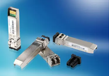
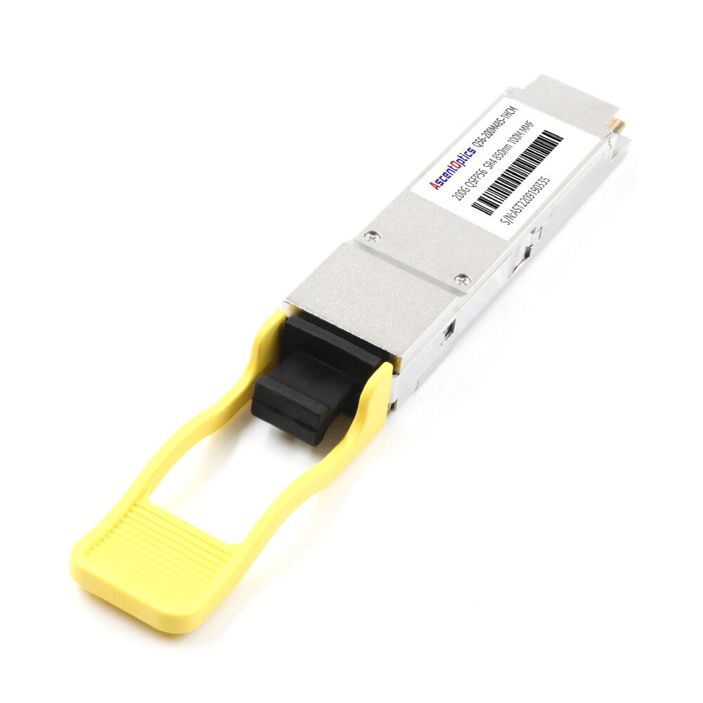
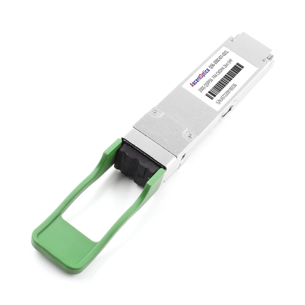
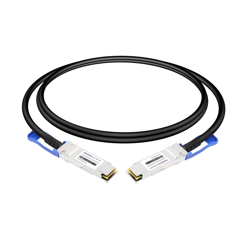
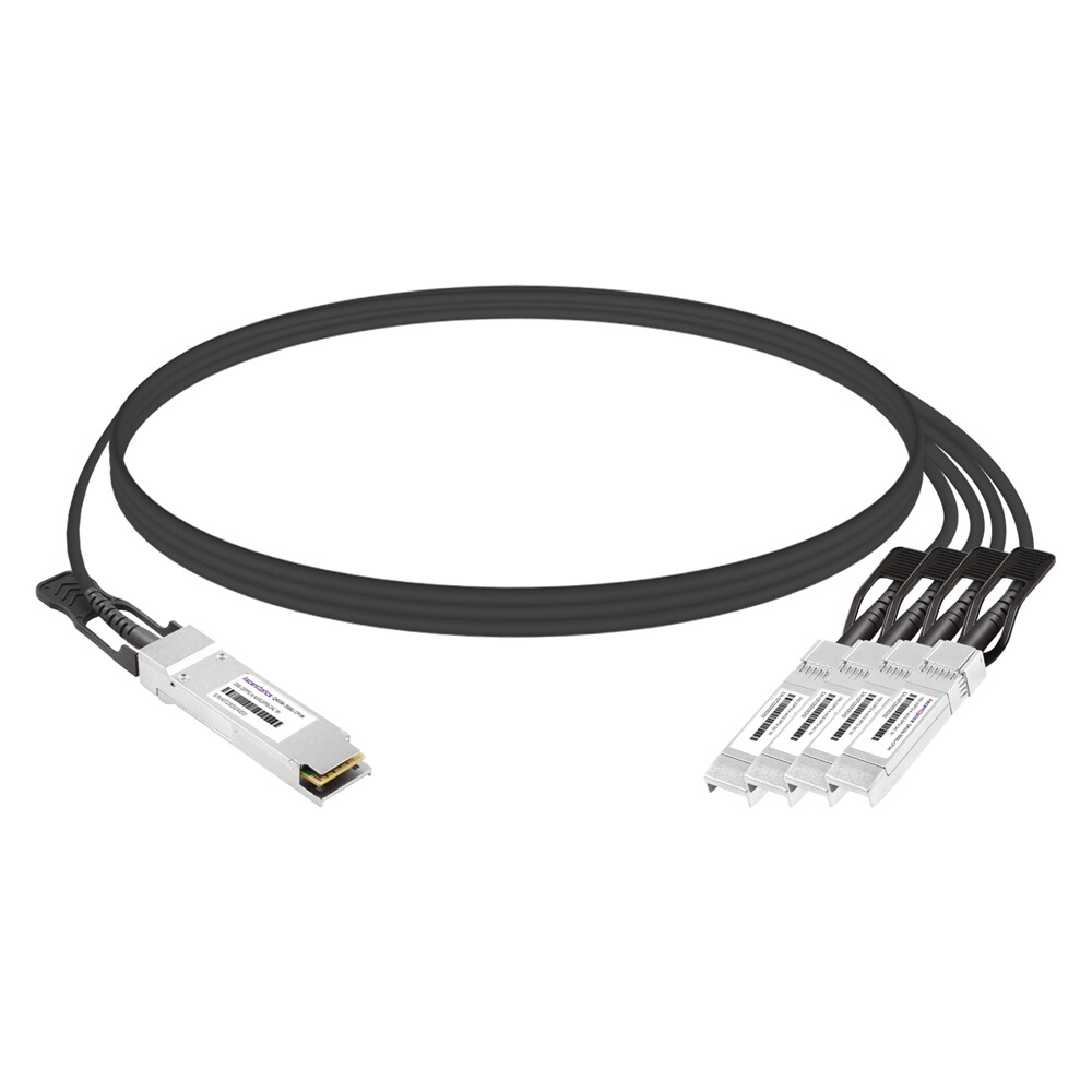
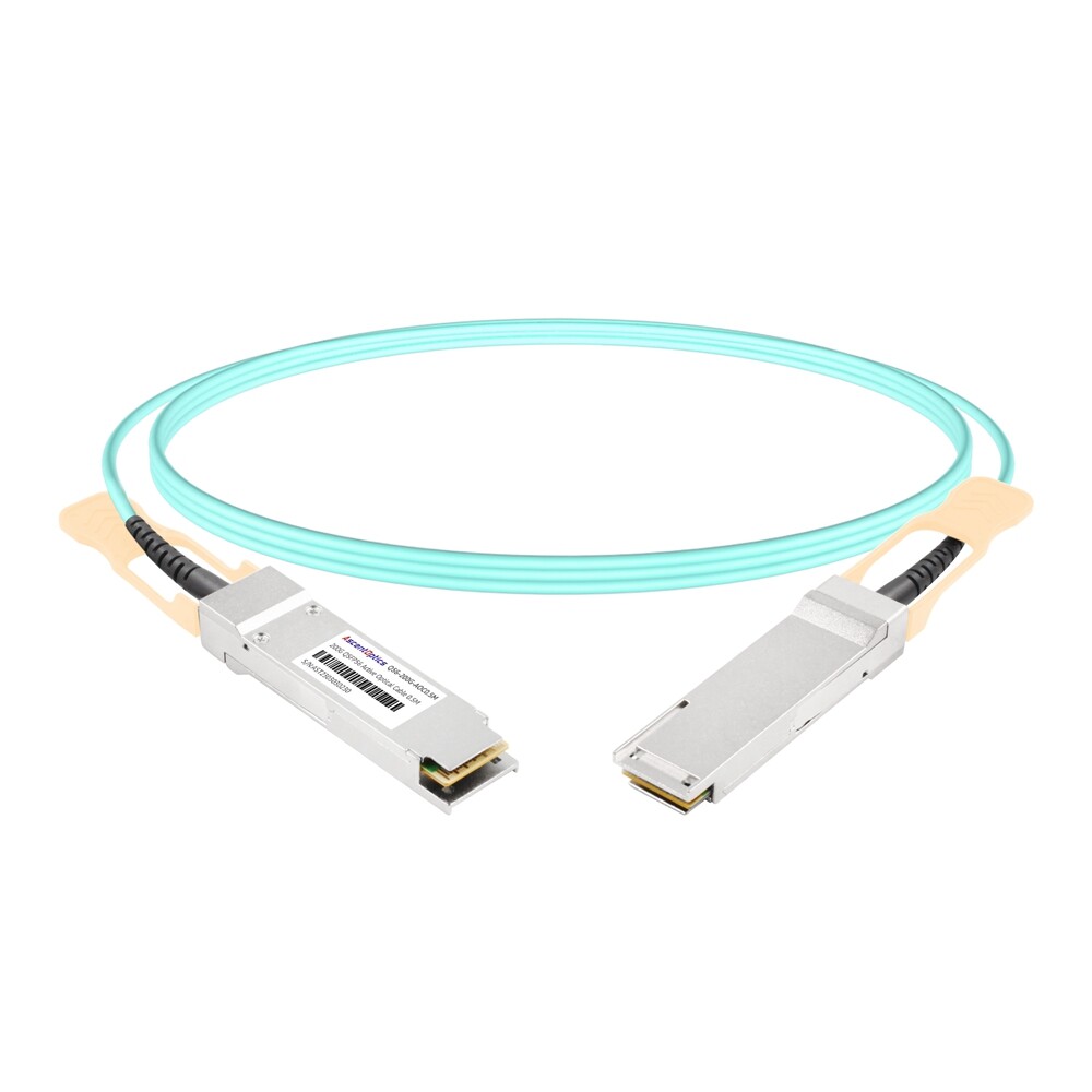
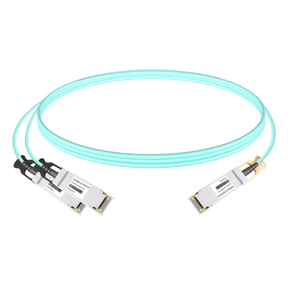
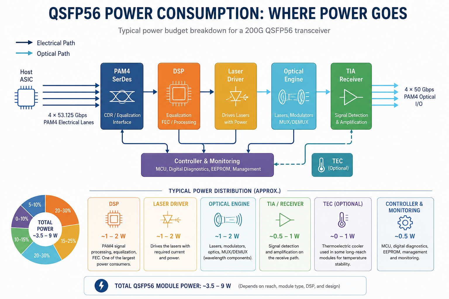
200G QSFP56 modules support four-channel, high-speed PAM4 communication in a very small form factor, having power dissipation that is normally between 4W and 7.5W. The major source of power dissipation in this module is the DSP chip necessary for PAM4 signal processing, adding 1-2W more to total dissipation. For most DSP-based QSFP56 modules, the digital signal processor (DSP) is one of the largest contributors to overall power consumption, typically accounting for around 1–2 W depending on the module architecture and vendor implementation.
What Is QSFP56?
A QSFP56 transceiver is a hot-pluggable optical module that supports 200 Gigabit Ethernet using four 50 Gbps PAM4 electrical lanes. QSFP56 power consumption typically ranges from 3.5 W for short-reach SR4 modules to 9 W for extended-reach ER4 modules.
QSFP56 stands for Quad Small Form-factor Pluggable 56. It uses the same mechanical package as QSFP28 but requires a host port capable of 200G PAM4 signaling. The four electrical lanes operate at approximately 53.125 Gbps each, including coding overhead, to deliver 200 Gbps aggregate bandwidth.
Key standards governing QSFP56 include:
- •IEEE 802.3bs-2017: Defines 200GbE and 400GbE Ethernet
- •IEEE 802.3cd-2018: Covers 200GBASE-SR4 and related 50GbE lanes
- •QSFP56 MSA: Specifies mechanical, electrical, and thermal interfaces
- •CMIS 4.0+: Provides digital diagnostics for real-time power and temperature monitoring
Because QSFP56 preserves the QSFP28 form factor, operators can reuse cages and cabling strategies while doubling per-port bandwidth. However, the jump from NRZ to PAM4 modulation increases power draw and thermal density.
QSFP56 Power Consumption by Module Type
QSFP56 power consumption depends primarily on reach class, modulation complexity, and whether the module uses a DSP. Short-reach multimode modules consume the least power. Long-reach single-mode modules require stronger lasers, tighter wavelength control, and more aggressive DSP, which increases wattage.
| Module Type |
Reach |
Fiber |
Typical Power |
Max Power |
| SR4 |
100 m (OM4) |
Multimode |
3.5–4.5 W |
5.0 W |
| DR4 |
500 m |
Single-mode |
4.0–5.0 W |
5.5 W |
| FR4 |
2 km |
Single-mode |
5.0–6.0 W |
6.5 W |
| LR4 |
10 km |
Single-mode |
6.0–7.0 W |
7.5 W |
| ER4 |
40 km |
Single-mode |
8.0–9.0 W |
9.0 W |
| LPO-SR4 |
100 m (OM4) |
Multimode |
~2.5 W |
3.0 W |
These figures represent common commercial-grade modules at room temperature. Actual values vary by vendor design, optical components, and operating conditions.
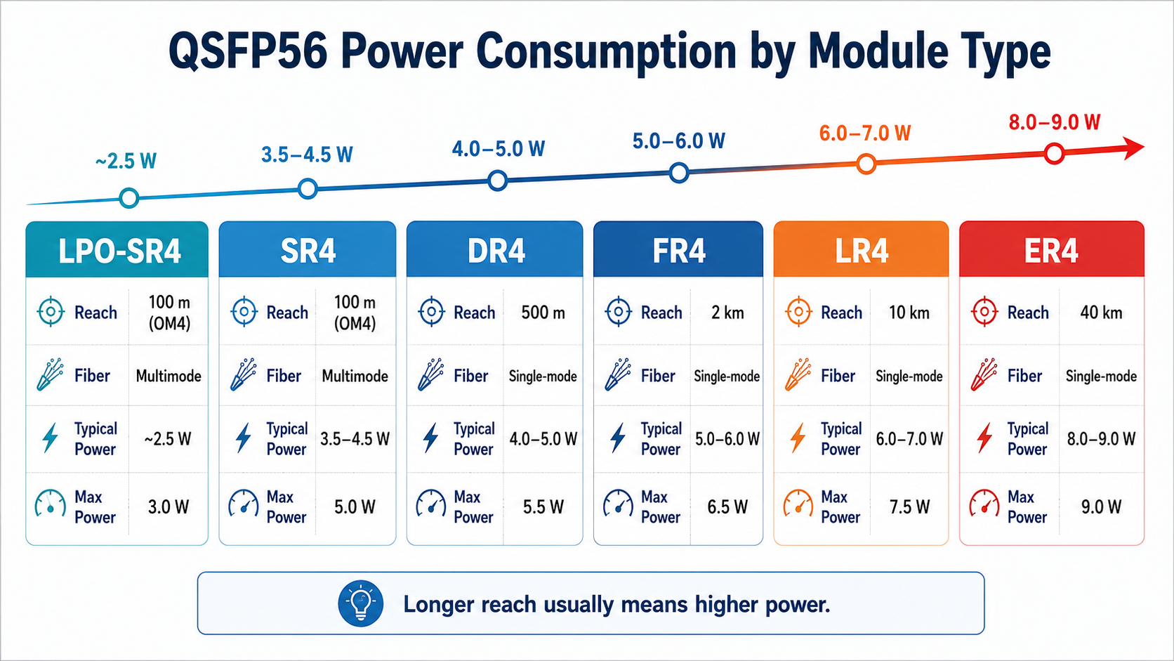
Why Longer-Reach Modules Use More Power
Long-reach QSFP56 modules consume more power for three reasons. First, the laser drivers must deliver higher optical output power to overcome fiber attenuation over distance. Second, CWDM and LWDM variants require additional wavelength multiplexing and demultiplexing optics. Third, DSP complexity increases because the receiver must recover weaker signals through stronger equalization and forward error correction.
For example, a 200GBASE-LR4 module transmitting 10 km must maintain signal integrity across four CWDM wavelengths while ensuring wavelength stability and optical power balance. The combined power penalty from laser drivers, thermal control circuitry (such as TECs in some module designs)and DSP processing pushes typical consumption to 6–7 W.
Temperature Dependence
QSFP56 power consumption rises with ambient temperature. A module that draws 5.0 W at 25°C may draw approximately 5.9 W at 70°C. This 18% increase comes from higher thermoelectric cooler power, increased laser bias current, and stronger DSP compensation for degraded signal quality.
Thermal design should always use maximum power specifications, not typical values. Equipment that passes validation at 25°C in a lab may fail thermal margins in a production data center running at higher intake temperatures.
What Affects QSFP56 Power Consumption?
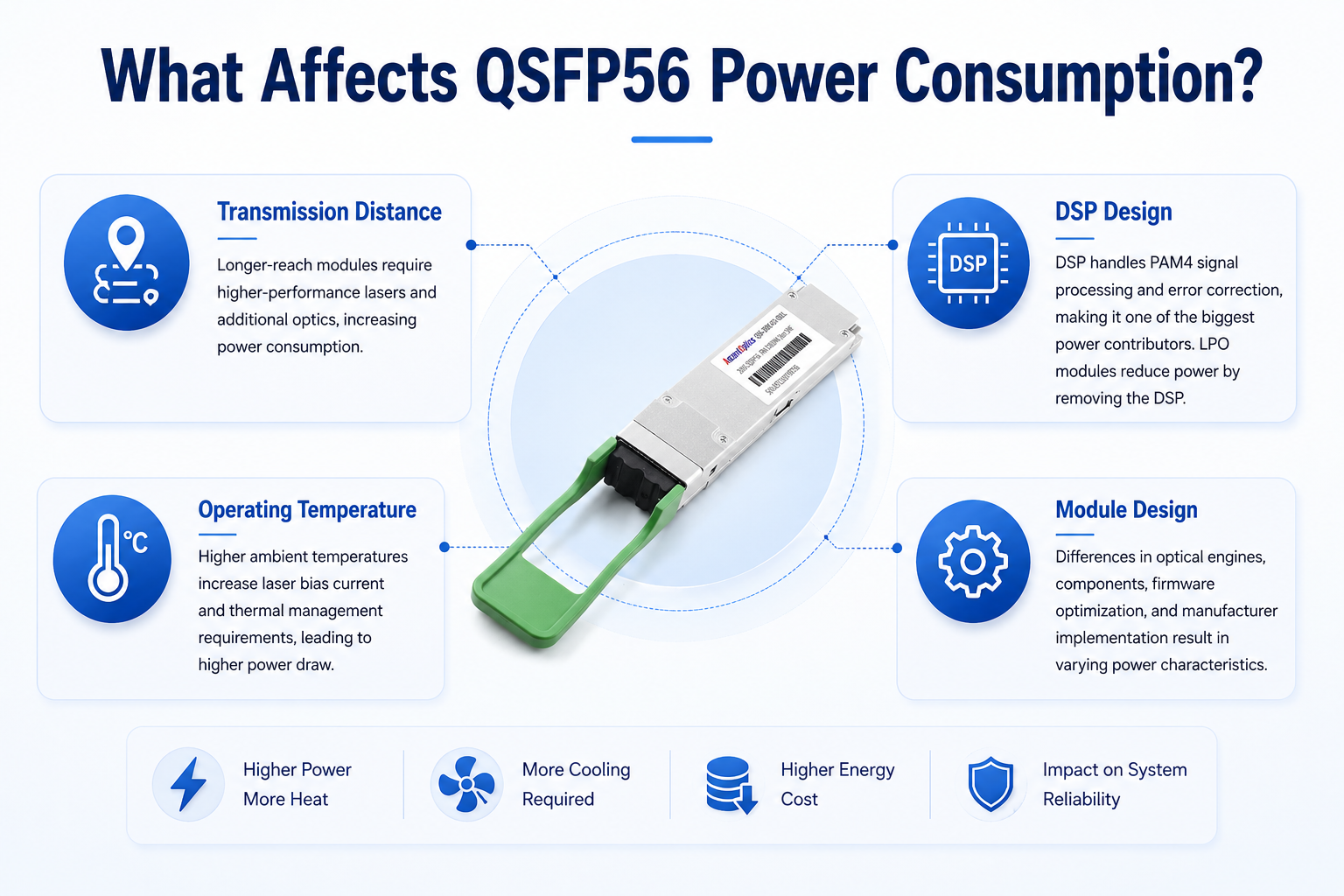
Several factors determine the power consumption of a QSFP56 module, even when the form factor remains the same.
Transmission Distance
Longer-reach modules generally consume more power because they require higher-performance lasers and additional optical components to maintain stable signal transmission.
DSP Design
Most QSFP56 modules use a DSP to compensate for PAM4 signal degradation. The DSP is one of the main contributors to module power consumption, while LPO modules reduce power by eliminating the onboard DSP.
Operating Temperature
Higher ambient temperatures increase laser bias current and thermal management requirements, causing the module to draw more power.
Module Design
Power consumption also varies by manufacturer. Differences in DSP implementation, optical components, and firmware optimization can result in slightly different power characteristics, even for modules with the same specifications.
Why QSFP56 Uses More Power Than QSFP28
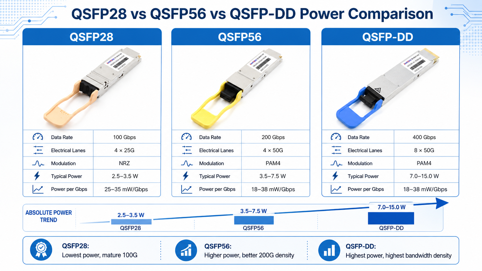
QSFP28 modules typically draw 2.5–3.5 W. QSFP56 modules draw 3.5–7.5 W. The increase comes from two technical changes: PAM4 modulation and the DSP required to recover PAM4 signals.
QSFP28 uses NRZ encoding, which transmits one bit per symbol using two signal levels. QSFP56 uses PAM4 encoding, which transmits two bits per symbol using four signal levels. PAM4 doubles throughput without doubling lane count, but the smaller voltage margin between levels makes the signal more susceptible to noise.
To compensate, QSFP56 modules include a digital signal processor (DSP). The DSP performs equalization, pre-emphasis, and forward error correction. The DSP alone adds roughly 1–2 W per module compared to NRZ-based designs.
Forward error correction (FEC) adds additional overhead. Many QSFP56 single-mode links require Reed-Solomon FEC on the host side or within the module. FEC improves link margin but consumes extra processing power and adds latency.
Despite the higher absolute wattage, QSFP56 is more efficient on a per-Gbps basis:
- •QSFP28 at 4.5 W / 100 Gbps = 45 mW/Gbps
- •QSFP56 at 6.0 W / 200 Gbps = 30 mW/Gbps
This efficiency improvement is why hyperscale operators accept the higher per-port power. They get twice the bandwidth in the same port density with better energy efficiency per bit.
Understanding qsfp56 power consumption requires comparing it against the form factors engineers most often evaluate: QSFP28 and QSFP-DD.
| Form Factor |
Data Rate |
Lanes |
Modulation |
Typical Power |
Power per Gbps |
| QSFP28 |
100 Gbps |
4 × 25G |
NRZ |
2.5–3.5 W |
~25–35 mW |
| QSFP56 |
200 Gbps |
4 × 50G |
PAM4 |
3.5–7.5 W |
~18–38 mW |
| QSFP-DD |
400 Gbps |
8 × 50G |
PAM4 |
7.0–15.0 W |
~18–38 mW |
QSFP56 sits in the middle of this progression. It consumes more power than QSFP28 but delivers better bandwidth density. QSFP-DD doubles bandwidth again but roughly doubles power consumption due to additional lanes and a larger module envelope.
When to Choose Each Form Factor
Choose QSFP28 when 100G bandwidth is sufficient and power budgets are tight. It remains the most mature and widely supported option.
Choose QSFP56 when you need 200G bandwidth in existing QSFP port density without moving to larger QSFP-DD or OSFP cages. It is the practical upgrade path for spine-leaf fabrics.
Choose QSFP-DD when 400G is required and the platform supports the deeper form factor. It offers the highest bandwidth per faceplate slot but demands more power and cooling headroom.
Switch-Level and Rack-Level Thermal Impact
The real impact of qsfp56 power consumption appears when you scale from one module to a full switch. A single 6 W module seems minor. Sixty-four of them in a 1RU switch generate serious heat.
Power per Fully Loaded Switch
| Module Type |
32-Port Switch |
64-Port Switch |
| All SR4 |
128–160 W |
256–320 W |
| All DR4 |
160–192 W |
320–384 W |
| All FR4 |
160–192 W |
320–384 W |
| All LR4 |
208–240 W |
416–480 W |
| All ER4 |
256–288 W |
512–576 W |
| All LPO-SR4 |
80–112 W |
160–224 W |
These figures represent optics-only power. They do not include the switch ASICs, power supplies, fans, or control plane components. A 64-port 200G switch with LR4 optics can easily exceed 1,000 W total system power.
Rack-Level Heat Load
Consider a typical four-switch rack populated with 32-port switches. The optics contribution alone produces:
| Configuration |
Optics Power |
BTU/hr |
CFM Required |
| 4 × 32-port, all SR4 |
512–640 W |
~1,750–2,180 |
74–93 |
| 4 × 32-port, all LR4 |
832–960 W |
~2,840–3,270 |
120–139 |
| 2 × 64-port, all SR4 |
512–640 W |
~1,750–2,180 |
74–93 |
| 4 × 64-port AI, all LPO |
320–400 W |
~1,090–1,360 |
46–58 |
Conversions use standard data center rules of thumb:
- •1 W = 3.41 BTU/hr
- •~0.145 CFM per watt at sea level
PUE multiplies the real cost. At PUE 1.5, 640 W of optics becomes 960 W of facility load. At PUE 1.8, it becomes 1,152 W.
Real-World Cooling Implications
Elena, a data center operations manager in Singapore, learned this lesson during a 100G-to-200G upgrade. Her team validated the new switches in a climate-controlled lab where intake air stayed at 22°C. In production, however, hot aisle containment gaps pushed intake temperatures above 30°C during peak summer weeks. The QSFP56 modules drew more power than expected, triggering thermal alarms. She had to add airflow baffles and rebalance CRAC unit loads before the rollout could continue.
This example shows why thermal design must account for worst-case intake temperatures, not nominal conditions. Front-to-back airflow, blanking panels, and hot/cold aisle containment all affect module-level temperatures.
Reducing QSFP56 Power Consumption: LPO, DAC, and AOC
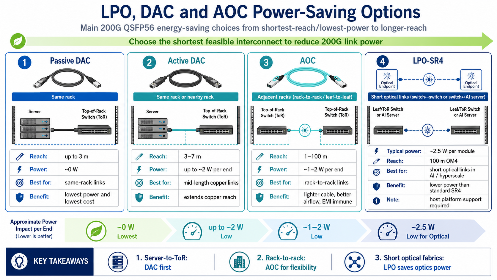
Engineers have three practical ways to reduce qsfp56 power consumption without sacrificing bandwidth: Linear Pluggable Optics (LPO), direct attach copper (DAC) cables, and active optical cables (AOCs).
Linear Pluggable Optics (LPO)
LPO modules eliminate the onboard DSP and rely on linear electrical interfaces together with host-side equalization. This cuts typical SR4 power from 3.5–4.5 W down to approximately 2.5 W. Across a 64-port switch, that saves roughly 64–128 W of optics heat.
LPO is not universally compatible. The switch must include an LPO-capable retimer or DSP on the host side. Without that support, standard QSFP56 modules are required.
LPO works best in two environments:
- 1. AI/ML clusters where power and latency are both critical
- 2. Hyperscale data centers with homogeneous switch platforms that support LPO
QSFP56 DAC and AOC Cables
For short-reach connections, cables often replace transceivers entirely.
- •Passive DAC: Draws approximately 0 W. Best for links under 3 meters inside a rack.
- •Active DAC: Uses redrivers or retimers and draws up to 2 W per end.
- •AOC: Embeds optics in the cable assembly and draws less than 4.5 W per end.
A passive DAC can reduce per-link power by over 90% compared to a standard optical transceiver pair. For top-of-rack to server connections, this is often the most power-efficient choice.
QSFP56 Power Monitoring and Thermal Management Best Practices
Effective thermal management starts with accurate measurement. Modern QSFP56 modules support CMIS 4.0 and later, which exposes digital diagnostics for temperature, voltage, TX/RX optical power, and bias current.
Use Max Power Specs, Not Typical
Always design thermal budgets around maximum power consumption, not typical values. A 32-port switch populated with LR4 modules may draw 208 W under normal conditions but should be provisioned for 240 W. Add another 15–20% margin for aging, dust accumulation, and elevated intake temperatures.
Monitor Module Temperature Under Load
Lab measurements at low traffic do not reflect production conditions. Monitor the module case temperature during peak traffic and under worst-case ambient conditions. The maximum case temperature for commercial-grade QSFP56 modules is typically 70°C. Industrial-grade modules extend to 85°C but usually consume 0.5–1 W more power per module.
Maintain Airflow Discipline
Even small airflow restrictions matter in dense switches. Verify that:
- •Front-to-back airflow paths remain unobstructed
- •Blank panels fill empty switch slots
- •Cable management does not block intake or exhaust vents
- •Hot aisle containment prevents recirculation
Plan for PUE Impact
Remember that every watt saved at the module level reduces facility load by 1.5× to 1.8× in typical data centers. Reducing optics power by 100 W can reduce total facility consumption by 150–180 W after cooling and power delivery losses.
QSFP56 Power in AI/ML Clusters
AI and machine learning clusters are among the most power-dense environments deploying QSFP56 today. A single GPU training rack may contain 256 or more 200G links connecting leaf switches to GPU servers.
At 5 W per module, 256 QSFP56 modules produce approximately 1,280 W of heat from optics alone. In a 40–50 kW AI rack, optics can represent 2.5–3% of total heat load. That percentage sounds small, but the concentration of heat at the rear of the chassis can affect adjacent components such as GPU HBM stacks.
LPO-SR4 becomes particularly attractive in these environments. Cutting per-module power from 5 W to 2.5 W reduces a 256-module rack from 1,280 W to 640 W of optics heat. The savings extend beyond energy costs. Lower module temperatures improve reliability and reduce fan speeds, which lowers acoustic noise and further reduces power consumption.
Conclusion
As 200G Ethernet continues to serve AI clusters, cloud computing, and enterprise backbone networks, understanding QSFP56 power consumption is becoming increasingly important for network planning. Selecting the right module type, optimizing airflow, and considering technologies such as LPO or DAC can significantly reduce thermal load while improving overall system efficiency. By balancing bandwidth, reach, and energy consumption, network designers can build more reliable and cost-effective high-speed infrastructures.
Frequently Asked Questions
What is the typical power consumption of a QSFP56 module?
A typical 200G QSFP56 module draws between 3.5 W and 7.5 W. Short-reach SR4 modules are at the low end, while extended-reach ER4 modules are at the high end.
Is QSFP56 hotter than QSFP28?
Yes. QSFP56 modules typically draw 3.5–7.5 W, while QSFP28 modules draw 2.5–3.5 W. The increase comes from PAM4 modulation and the DSP required for signal recovery.
Why does QSFP56 use more power?
QSFP56 uses PAM4 signaling with four signal levels instead of NRZ’s two levels. The DSP chip that recovers the PAM4 signal adds roughly 1–2 W per module.
Does QSFP56 power consumption increase with temperature?
Yes. Power can increase by approximately 18% from 25°C to 70°C ambient. Thermal design should account for worst-case operating temperatures.
How much heat does a fully loaded QSFP56 switch generate?
A 32-port switch populated with SR4 modules generates 128–160 W of optics-only heat. The same switch with LR4 modules generates 208–240 W.
Can LPO reduce QSFP56 power and cooling costs?
Yes. LPO-SR4 modules can cut power by 30–50% compared to standard SR4. A 64-port switch can save 64–128 W of optics heat by using LPO.
What is the maximum case temperature for QSFP56?
Commercial-grade QSFP56 modules are typically rated for 0°C to 70°C case temperature. Industrial-grade modules extend from -40°C to 85°C.
Can I use a QSFP56 module in a QSFP28 port?
No. Although the physical connector fits, QSFP56 requires a host port that supports 200G PAM4 signaling. A QSFP28 module can operate in a QSFP56 port at 100 Gbps, but the reverse is not supported.
Does QSFP56 support low-power mode?
Yes. Most QSFP56 modules support Low Power Mode (LPMode) defined by the QSFP56 MSA and CMIS specifications, allowing switches to reduce module power during initialization or maintenance.
Does fiber type affect QSFP56 power consumption?
Indirectly. Longer-reach single-mode modules generally consume more power because they require higher-performance lasers, wavelength management, and more sophisticated signal processing than multimode SR4 modules.
Post Views: 788