A QSFP+ module and a QSFP28 module look identical and slide into the same port cage, but installing the wrong one can leave a 100G-capable switch running at 40 Gbps—or not running at all. QSFP compatibility is not determined by size alone; it depends on electrical lane speed, switch ASIC support, firmware version, and even thermal budget.
Network engineers planning upgrades often assume that backward-compatible ports mean any QSFP module will work. The reality is more nuanced: a QSFP28 port accepts a QSFP+ module, but a QSFP+ port cannot run a QSFP28 module at 100 Gbps. Understanding these rules before procurement saves hours of troubleshooting, prevents unplanned switch upgrades, and protects network stability during migration.
What Is QSFP Compatibility?
QSFP compatibility refers to whether an optical transceiver module of a given form factor, electrical interface, and data transmission rate will function correctly in a specific switch port.
Several factors determine whether a module works:
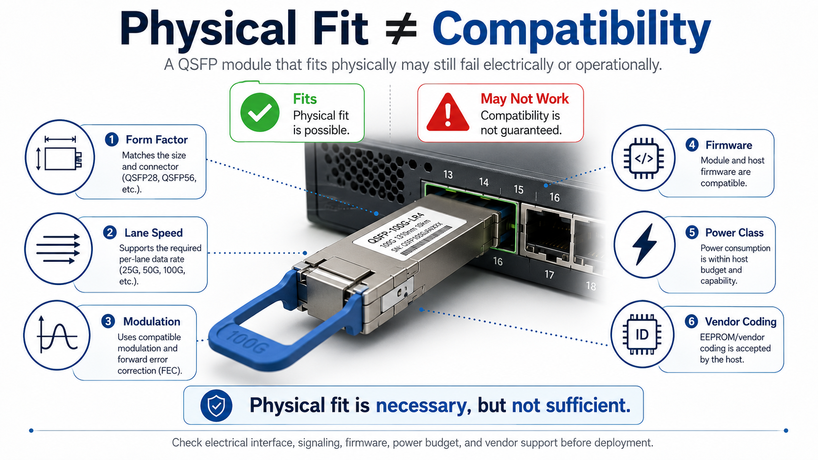
- •Form factor: QSFP+, QSFP28, QSFP56, and QSFP-DD share similar dimensions but use different electrical connectors and lane counts.
- •Electrical lane speed: QSFP+ uses 10 Gbps lanes, QSFP28 uses 25 Gbps lanes, QSFP56 uses 50 Gbps lanes, and QSFP-DD uses up to 100 Gbps lanes.
- •Modulation: NRZ signaling for 40G and 100G; PAM4 for 200G, 400G, and 800G.
- •Firmware support: Switch software must recognize the module and configure the port correctly.
- •Power class: A module that fits may draw more power than the port or switch can support.
- •EEPROM vendor coding: Some switches reject modules that do not carry an approved vendor identifier.
In short, physical fit is necessary but not sufficient. A module that slides into the cage must also match the port’s electrical, optical, and management requirements.
Why Compatibility Matters in Data Center Networks
Compatibility mistakes cause three common problems:
- Procurement risk: Ordering hundreds of QSFP28 modules for a QSFP+ switch wastes budget and delays deployment.
- Unplanned upgrades: A module that is mechanically compatible but electrically unsupported can force a switch or line-card replacement.
- Network instability: Speed mismatches, FEC errors, or vendor lock-in can cause links to flap or fail during production traffic.
For data center and telecom environments, verifying compatibility before installation is as important as verifying fiber type and transmission distance.
QSFP Form Factor Overview
The QSFP family includes four main variants used in modern optical networking infrastructure. Each variant builds on the same small form-factor pluggable concept but increases data transmission capacity through more lanes or higher lane speeds.
| Module |
Data Rate |
Lanes |
Lane Speed |
Modulation |
Typical Power |
Common Connector |
| QSFP+ |
40 Gbps |
4 |
10 Gbps |
NRZ |
1.5–3.5 W |
MPO-12 or LC duplex |
| QSFP28 |
100 Gbps |
4 |
25 Gbps |
NRZ |
3.5–5.5 W |
MPO-12 or LC duplex |
| QSFP56 |
200 Gbps |
4 |
50 Gbps |
PAM4 |
4–7 W |
MPO-12 or LC duplex |
| QSFP-DD |
400/800 Gbps |
8 |
50/100 Gbps |
PAM4 |
8–25 W |
MPO-16, MPO-12, or LC duplex |
QSFP+ modules deliver 40 Gbps over four 10 Gbps NRZ lanes. They follow the QSFP+ MSA and the SFF-8436 specification for mechanical, electrical, and management interfaces. QSFP+ remains common in legacy data center networks and enterprise core switches.
QSFP28 modules deliver 100 Gbps over four 25 Gbps NRZ lanes. They comply with the QSFP28 MSA, IEEE 802.3ba, IEEE 802.3bm, IEEE 802.3cd, IEEE 802.3bs, IEEE 802.3cu and SFF-8665/8679/8680 specifications. QSFP28 is the dominant form factor for 100G data center interconnect and spine-leaf architectures.
QSFP56 modules deliver 200 Gbps over four 50 Gbps PAM4 lanes. They use the same mechanical form factor as QSFP+ and QSFP28 but require host ports that support PAM4 signaling at 50 Gbps per lane.
QSFP-DD (Quad Small Form-factor Pluggable Double Density) uses an eight-lane electrical interface. It supports 400G Ethernet using 8 × 50G PAM4 electrical lanes, while the newer QSFP-DD800 variant supports 800G using 8 × 100G PAM4 lanes. The QSFP-DD MSA designed the form factor to accept older QSFP modules mechanically while adding four extra lanes for higher speeds. QSFP-DD modules typically implement the Common Management Interface Specification (CMIS), maintained by the Optical Internetworking Forum (OIF). Earlier QSFP modules generally use the SFF-8636 management interface.
QSFP Compatibility Matrix
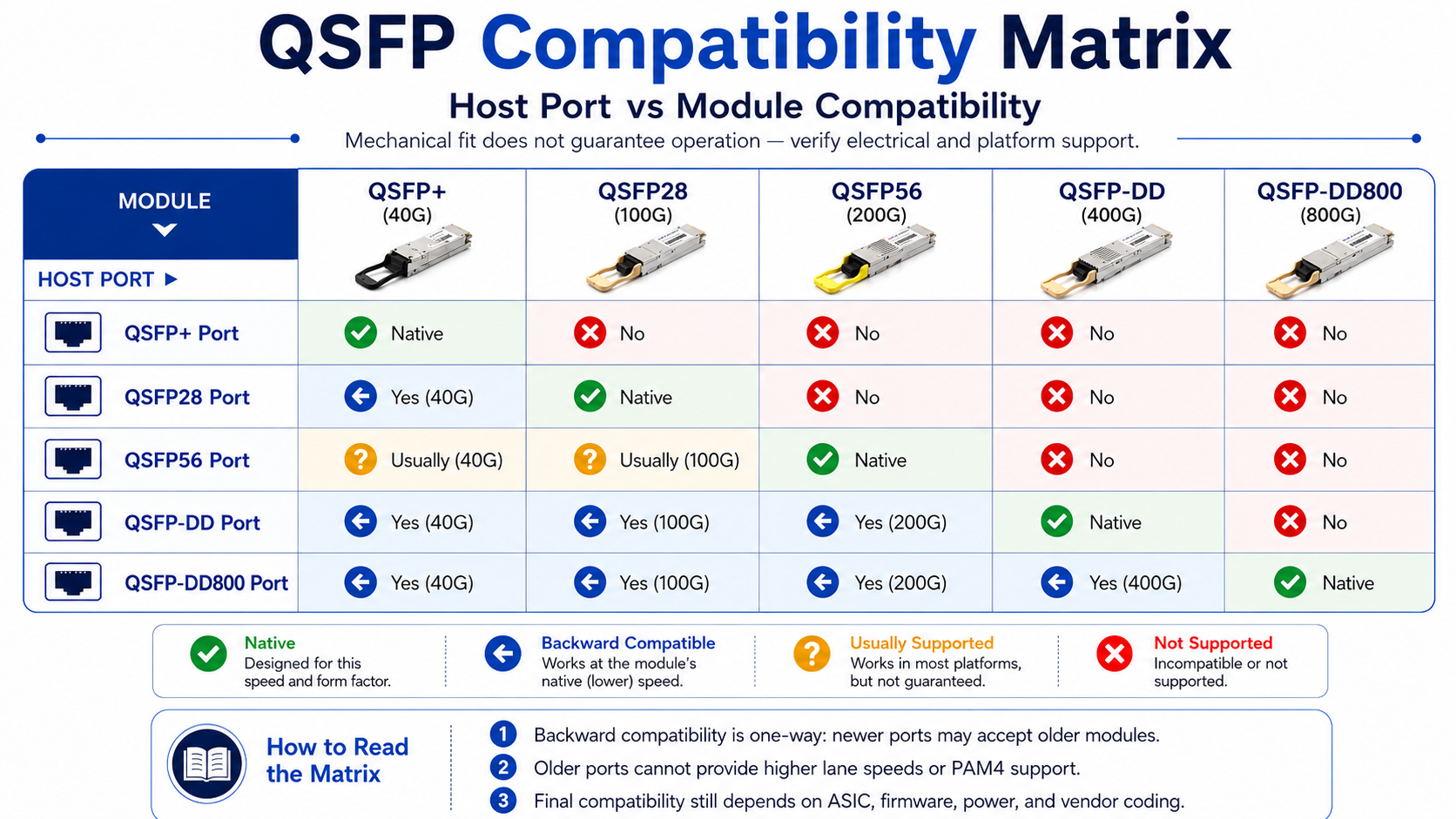
The easiest way to avoid mistakes is to consult a port-vs-module compatibility matrix before ordering. The table below covers the most common combinations.
| Host Port |
QSFP+ (40G)
|
QSFP28 (100G) |
QSFP56 (200G) |
QSFP-DD (400G) |
QSFP-DD800 (800G)
|
| QSFP+ port |
Native
|
No |
No |
No |
No
|
| QSFP28 port |
Yes (40G)
|
Native |
No |
No |
No
|
| QSFP56 port |
Usually (40G)
|
Usually (100G) |
Native |
No |
No
|
| QSFP-DD port |
Yes (40G)
|
Yes (100G) |
Yes (200G) |
Native |
No
|
| QSFP-DD800 port |
Yes (40G)
|
Yes (100G) |
Yes (200G) |
Yes (400G) |
Native
|
What “Backward Compatible” Actually Means
A newer port is backward compatible when it accepts an older module and runs it at the older module’s native data transmission rate. For example, a QSFP28 port accepts a QSFP+ module and operates it at 40 Gbps. The reverse is not true: an older QSFP+ port cannot support a QSFP28 module at 100 Gbps because the switch ASIC lacks the 25 Gbps SerDes lanes required by QSFP28.
This one-way compatibility is important for phased upgrades. A data center can deploy QSFP-DD switches, continue using existing QSFP28 modules, and upgrade to 400G optics later without replacing the switch.
Forward vs Backward Compatibility Explained
The difference between forward and backward compatibility comes down to electrical lane speed, not physical shape.
Backward compatibility works because the newer port already supports all lane speeds below its maximum. A QSFP28 port can run 10 Gbps lanes (QSFP+) and 25 Gbps lanes (QSFP28). A QSFP-DD or QSFP-DD800 host may support 10G, 25G, 50G, or 100G electrical lanes, depending on the ASIC design and firmware.
Forward compatibility fails because older ports do not gain new electrical capabilities. A QSFP+ port only has 10 Gbps SerDes lanes. It cannot reconfigure itself to support the 25 Gbps lanes of QSFP28 or the 50 Gbps PAM4 lanes of QSFP56.
Modulation Differences: NRZ vs PAM4
- NRZ (Non-Return-to-Zero): Each symbol carries one bit. Used by QSFP+ (10 Gbps per lane) and QSFP28 (25 Gbps per lane).
- PAM4 (Pulse Amplitude Modulation 4): Each symbol carries two bits. Used by QSFP56 (50 Gbps per lane), QSFP-DD 400G (50 Gbps per lane), and QSFP-DD800 (100 Gbps per lane).
Because PAM4 and NRZ use different signaling schemes, a port that only supports NRZ cannot decode a PAM4 module, even if the physical dimensions match.
QSFP Standards and MSA Compliance
QSFP interoperability begins with industry standards and Multi-Source Agreements (MSAs). These documents define mechanical dimensions, electrical interfaces, optical specifications, and management protocols so that modules from different vendors can work in the same port.
| Standard / MSA |
Applies To |
Defines |
| SFF-8436 |
QSFP+ |
Mechanical, electrical, and management interfaces for 40G QSFP+ modules |
| IEEE 802.3ba |
40G / 100G Ethernet |
40GBASE-SR4/LR4/ER4 and 100GBASE-SR10/LR4/ER4 optical PMDs |
| IEEE 802.3bm |
100G Ethernet |
100GBASE-SR4 and the CAUI-4 electrical interface used by QSFP28 |
| QSFP28 MSA + SFF-8665/8679/8680 |
QSFP28 |
100G module specifications, connectors, and cages |
| SFF-8636 / CMIS |
QSFP+/QSFP28/QSFP-DD |
Common Management Interface Specification for diagnostics and control |
| QSFP-DD MSA |
QSFP-DD |
Double-density form factor for 400G/800G modules |
Why MSA Compliance Alone Does Not Guarantee Switch Recognition
A module can be fully MSA-compliant and still be rejected by a switch. Many vendors use EEPROM-based authentication to limit support to modules coded with their vendor identifier. The switch reads the vendor name, OUI, and part number from the module’s memory and compares them against an internal allow list.
MSA compliance ensures the module meets the physical and electrical specifications. Vendor coding determines whether the switch accepts the module without warnings or error-disabled states.
QSFP Breakout Cables and Adapter Compatibility
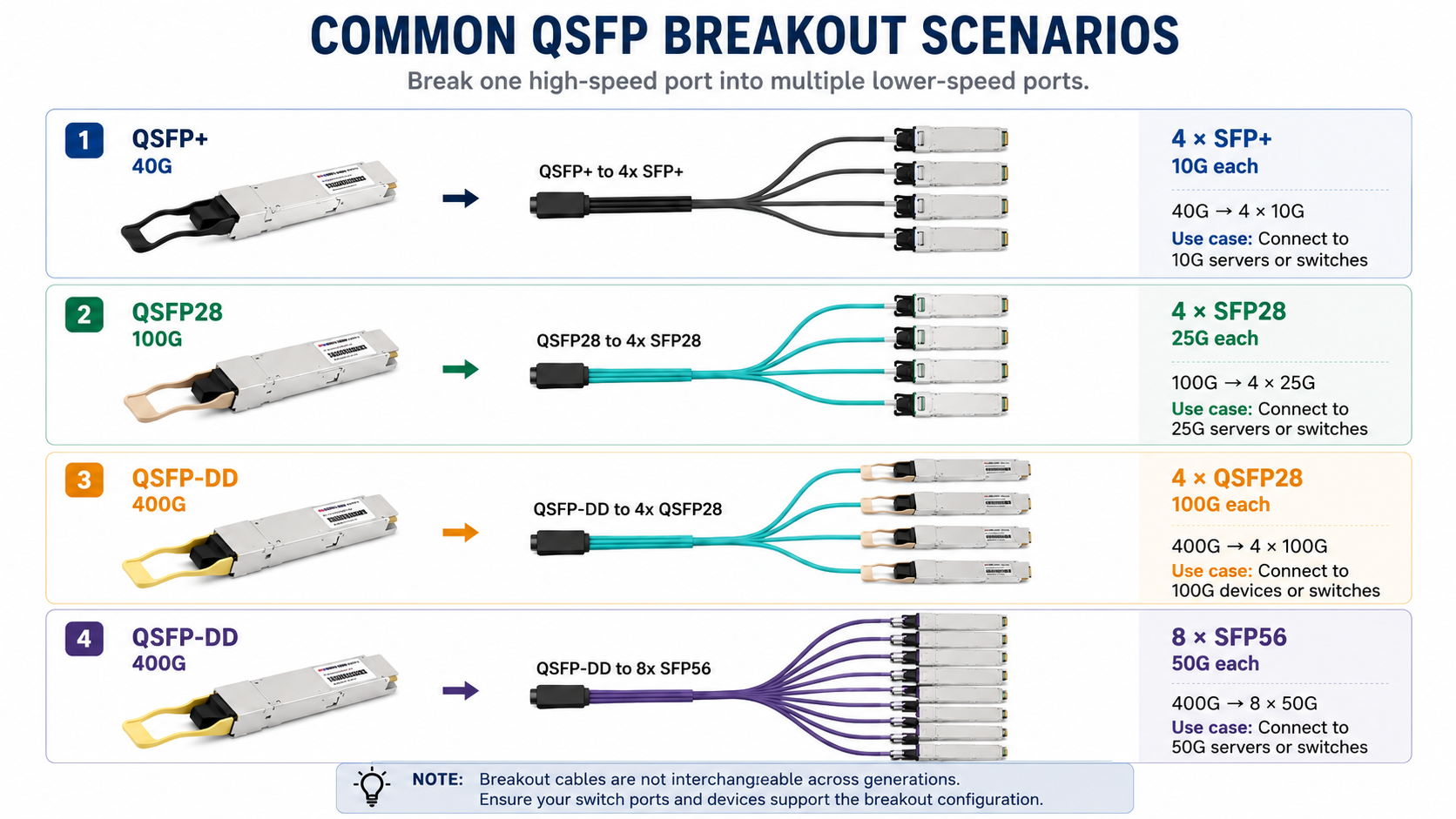
Breakout cables split one high-speed QSFP port into multiple lower-speed lanes. However, breakout cables are not interchangeable across QSFP generations because each generation uses different lane speeds.
| Breakout Type |
Source Form Factor |
Breaks Into
|
Use Case
|
| QSFP+ to 4×SFP+ |
QSFP+ |
4 × 10 Gbps SFP+ |
Connect the 40G switch port to four 10G servers |
| QSFP28 to 4×SFP28 |
QSFP28 |
4 × 25 Gbps SFP28 |
Connect a 100G switch port to four 25G servers |
| QSFP-DD to 4×QSFP28 |
QSFP-DD |
4 × 100 Gbps QSFP28 |
Connect the 400G switch port to four 100G switches |
| QSFP-DD to 8×SFP56 |
QSFP-DD |
8 × 50 Gbps SFP56 |
Connect a 400G switch port to eight 50G hosts |
QSA (QSFP-to-SFP Adapter) Use Cases
A QSA adapter lets a QSFP port accept a single SFP or SFP+ module. This is useful when you need to connect a low-speed device to a high-speed port. However, the adapter only activates one lane, so it does not convert a 100G port into four 10G ports. For that, you need a breakout cable.
Power Class and Thermal Compatibility
A module that fits and is electrically compatible can still fail if it draws more power than the port or switch can dissipate. QSFP power classes define the maximum power a module may consume.
| Form Factor |
Typical Power Range |
Notes |
| QSFP+ |
1.5–3.5 W |
Low heat, minimal cooling requirements |
| QSFP28 |
3.5–5.5 W |
Standard 100G modules stay below 5 W |
| QSFP56 |
4–7 W |
PAM4 DSP adds modest power increase |
| QSFP-DD |
8–25 W |
Class 4 to Class 8; high-power coherent modules exceed 15 W |
A fully populated 32-port QSFP-DD switch with Class 8 modules can draw 480 W or more for optics alone. Before deploying high-power modules, verify that the switch’s thermal design, airflow, and power supplies can handle the load.
Common QSFP Compatibility Issues and Troubleshooting
Even with the correct module and port, issues can occur. The table below lists common symptoms, likely causes, and first-step fixes.
| Symptom |
Likely Cause |
First Step |
| Module not detected |
Vendor lock-in or firmware mismatch |
Check the EEPROM with show interfaces transceiver detail |
| “Unsupported transceiver” warning |
Vendor coding not approved |
Apply the platform unlock command or use vendor-coded modules |
| Link up, but errors or flapping |
FEC mismatch or dirty fiber |
Verify FEC mode and clean MPO/MTP connectors |
| Speed mismatch |
Port configured for wrong rate |
Set port speed to match module lane capability |
| CMIS state machine hangs |
Firmware does not support CMIS revision |
Upgrade switch firmware |
| High temperature alarm |
Power class exceeds thermal budget |
Reduce port density or improve airflow |
Diagnostic Workflow
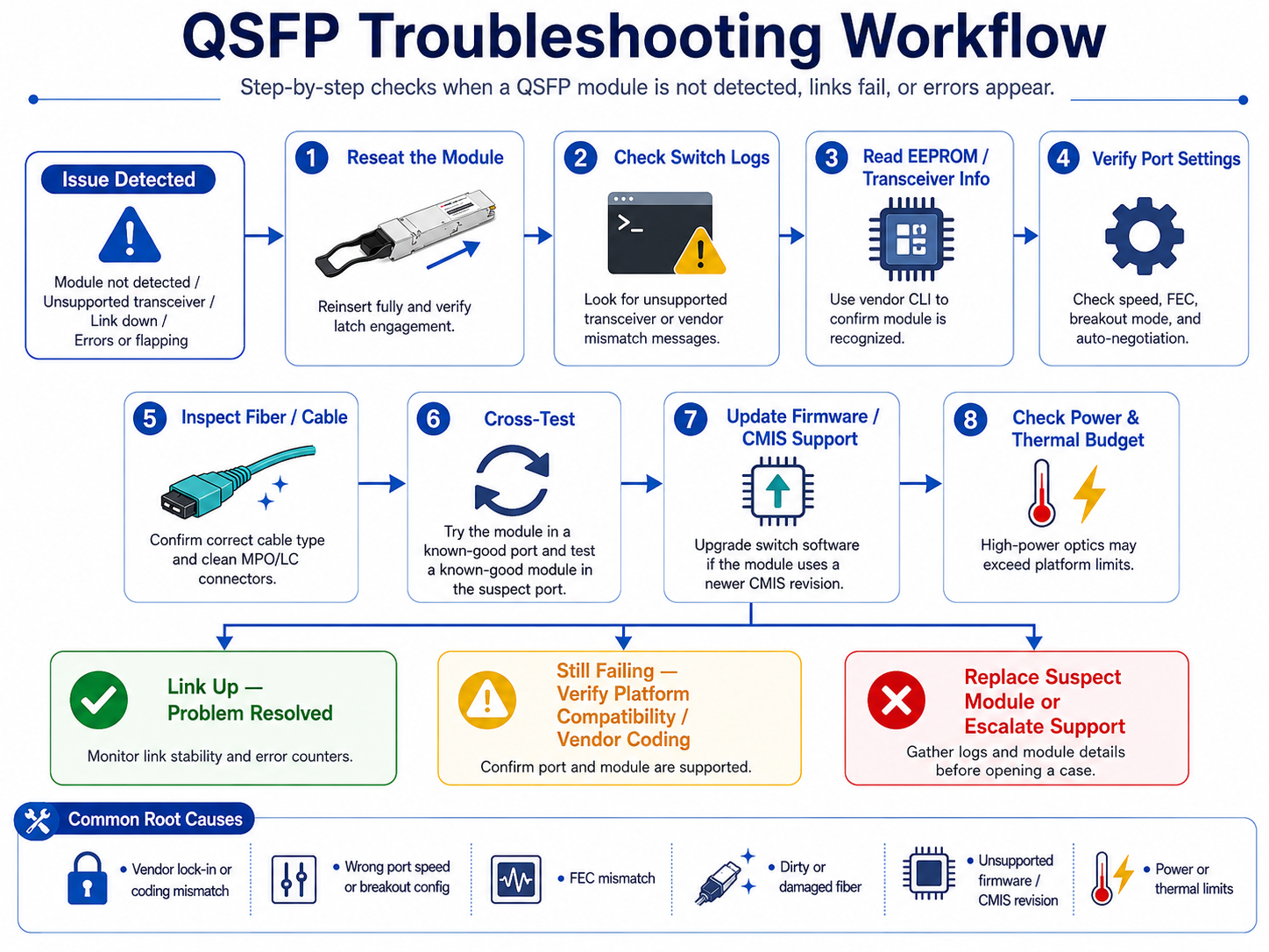
When a QSFP module does not behave as expected, follow these steps:
- 1. Reseat the module and confirm the latch engages fully.
- 2. Check switch logs for unsupported transceiver or vendor mismatch messages.
- 3. Verify EEPROM readability using vendor CLI commands.
- 4. Confirm the port speed, FEC, and breakout configuration match the module.
- 5. Test the module in a known-good port and insert a known-good module in the suspect port.
- 6. Update switch firmware if the module uses a newer CMIS revision.
Does Physical Compatibility Guarantee Interoperability?
Although QSFP modules share standardized mechanical dimensions, interoperability depends on several additional factors, including host ASIC support, firmware, EEPROM coding, CMIS compatibility, FEC configuration, and thermal design. A physically compatible module may still fail to initialize if any of these requirements are not met.
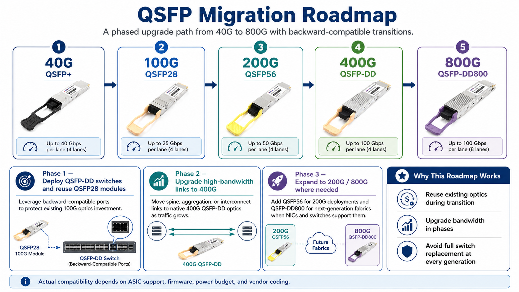
QSFP Migration Roadmap: 40G to 800G
Backward-compatible QSFP ports make network upgrades easier because you can reuse existing optics during transition phases. A typical migration path looks like this:
- Phase 1: Deploy QSFP-DD switches and reuse existing QSFP28 modules in backward-compatible ports. This protects existing investments while preparing the fabric for higher speeds.
- Phase 2: Upgrade high-bandwidth spine links to 400G QSFP-DD modules as traffic grows.
- Phase 3: Add 200G QSFP56 or 800G QSFP-DD800 modules when NICs and switches support them.
This staged approach lets organizations scale optical networking infrastructure without replacing switches at every generation.
Compatibility Best Practices
Selecting the right QSFP module involves more than matching the connector or form factor. Following these best practices can help prevent compatibility issues, reduce deployment risks, and ensure long-term network reliability.
Verify Switch and ASIC Compatibility
Before purchasing transceivers, confirm that your switch model and ASIC support the required module type, lane speed, and signaling technology. Even if a module fits physically, older hardware may not support higher-speed SerDes, PAM4 signaling, or specific breakout configurations.
Check Firmware and CMIS Support
Many modern QSFP-DD and QSFP-DD800 modules rely on the Common Management Interface Specification (CMIS). Ensure your switch firmware supports the required CMIS version and module features. Updating the operating system or firmware before deployment can prevent module initialization and management issues.
Match Speed, FEC, and Breakout Configuration
Configure the switch port to match the module’s operating speed and breakout mode. Verify that both ends of the link use compatible Forward Error Correction (FEC) settings, as mismatched FEC configurations are a common cause of link failures and excessive bit errors.
Consider Power and Thermal Budget
Higher-speed optical modules consume significantly more power than earlier generations. Before deploying large numbers of 400G or 800G transceivers, verify that the switch supports the required power class and provides sufficient airflow for reliable operation in fully populated systems.
Use Qualified or Vendor-Compatible Optics
Although MSA-compliant modules are designed for interoperability, some network equipment vendors enforce EEPROM-based module authentication. Using properly coded compatible optics or vendor-qualified transceivers helps avoid unsupported transceiver warnings and ensures full functionality.
Validate Before Large-Scale Deployment
Whenever possible, test new modules in a small pilot environment before rolling them out across production networks. Verifying interoperability, firmware compatibility, and link stability in advance can significantly reduce deployment time and troubleshooting costs.
Conclusion
QSFP compatibility extends far beyond mechanical fit. Successful deployment depends on multiple factors, including electrical lane architecture, signaling technology, firmware support, power requirements, and switch vendor implementation. Understanding how these elements interact helps avoid costly compatibility issues and simplifies network upgrades.
As data centers continue migrating from 40G and 100G to 200G, 400G, and 800G Ethernet, choosing transceivers that match both current infrastructure and future expansion plans becomes increasingly important. By verifying compatibility before deployment and following industry best practices, organizations can protect existing investments, reduce operational risks, and build scalable, high-performance networks that are ready for next-generation AI, cloud, and enterprise applications.
Frequently Asked Questions
Are QSFP modules from different vendors interchangeable?
QSFP modules adhere to Multi-Source Agreement (MSA) standards; therefore, modules from different vendors are mechanically and electrically interchangeable. However, many switch OEMs (such as Cisco, Juniper, Arista, etc.) encode vendor-specific identifiers into their optical modules. Third-party compatible modules must be correctly coded for your specific switch.
What is the power consumption of QSFP modules?
Typical power consumption ranges from 1.5W for QSFP+ SR4 to 3.5W for QSFP28 SR4, 4.5W for QSFP56, and 7–12W for QSFP-DD modules. In high-density deployment scenarios, thermal management may need to be considered for high-power modules.
Are QSFP modules backward compatible with lower-speed ports?
Generally, yes—QSFP-DD ports support QSFP56, QSFP28, and QSFP+ modules, while QSFP28 ports support QSFP+ modules. However, the link will operate at the lowest common speed supported by both components.
Can I use a QSFP28 100G module in a QSFP-DD 400G port?
In most cases, yes. QSFP-DD ports are physically and electrically backward compatible with QSFP28 modules. The host port can be configured to operate at 100G if the switch ASIC and operating system support backward compatibility. This enables a smooth network migration from 100G to 400G without requiring the replacement of all optical modules at once.
What types of cables do QSFP modules support?
QSFP modules support DACs (Direct Attach Copper cables for short-range links up to 5–7 meters), AOCs (Active Optical Cables for links up to 100 meters), and optical transceivers using LC or MPO/MTP interfaces (for longer-distance transmission). Single-mode fiber (SMF) supports transmission distances ranging from 10 km to over 80 km. Multi-mode fiber (MMF) using MPO-12 or MPO-16 connectors supports transmission distances of 100 m to 500 m, depending on the Ethernet or InfiniBand standard.
Can a QSFP56 port run a QSFP28 module?
In many cases, yes. Since QSFP56 ports support both PAM4 and NRZ signaling, they can often operate QSFP28 modules at 100G. However, support depends on the switch ASIC and firmware implementation, so compatibility should always be verified with the vendor.
Post Views: 34


