Deploying the QSFP112 module carries significant risks. Even a single compatibility oversight can bring the entire project to a standstill. Incorrect temperature calculations may force a rack redesign. A polarity check error could even render the leaf-spine link inoperable for hours.
Pre-Deployment Verification
Skipping pre-deployment checks is the single most common cause of QSFP112 deployment delays. A structured verification process prevents compatibility mismatches, thermal overloads, and cabling errors before a single module is installed.
Host Platform Compatibility Check
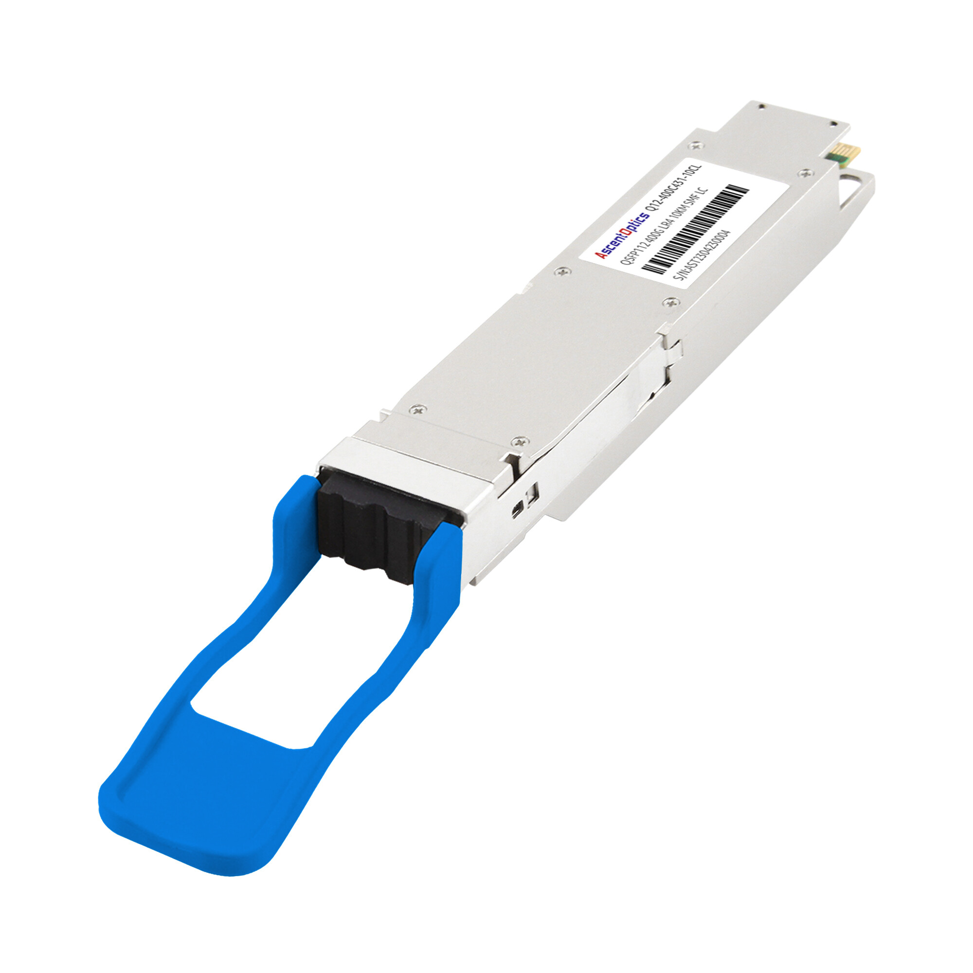
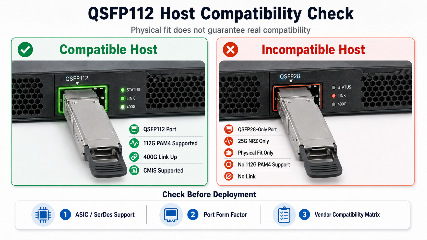
QSFP112 modules share the same mechanical form factor as QSFP28, but the electrical interface is fundamentally different. QSFP112 uses 112G PAM4 signaling across four lanes to achieve a 400Gbps total data transmission rate. QSFP28 uses 25G NRZ signaling. A QSFP112 module will physically seat in a QSFP28 port, but it will not function.
Verify the following before ordering modules:
- •ASIC SerDes support: Confirm the switch or NIC ASIC supports 112G PAM4. Common platforms supporting QSFP112 include NVIDIA ConnectX-7 NICs, NVIDIA Quantum-2 InfiniBand switches, Broadcom Tomahawk5 Ethernet switches, Jericho3-AI platforms, and selected Intel IPU solutions with native 112G PAM4 SerDes support.
- •Port form factor: Verify whether your equipment uses QSFP112, QSFP-DD, or OSFP. These are not interchangeable without adapters.
- •Vendor compatibility matrix: Review your switch vendor’s compatibility list. Some vendors restrict third-party optical transceiver modules through firmware checks.
Fiber Plant Audit
Matching the fiber infrastructure to the module variant is critical. A mismatch between fiber type and optical module will degrade signal integrity or prevent link establishment entirely.
| Module Variant |
Fiber Type |
Connector |
Reach |
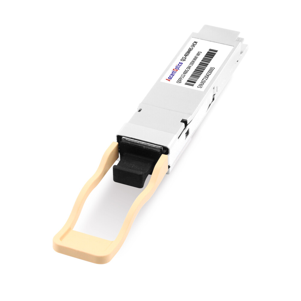
| SR4 |
OM4 / OM5 |
MPO-12 APC |
50m OM4 / 100m OM5 |
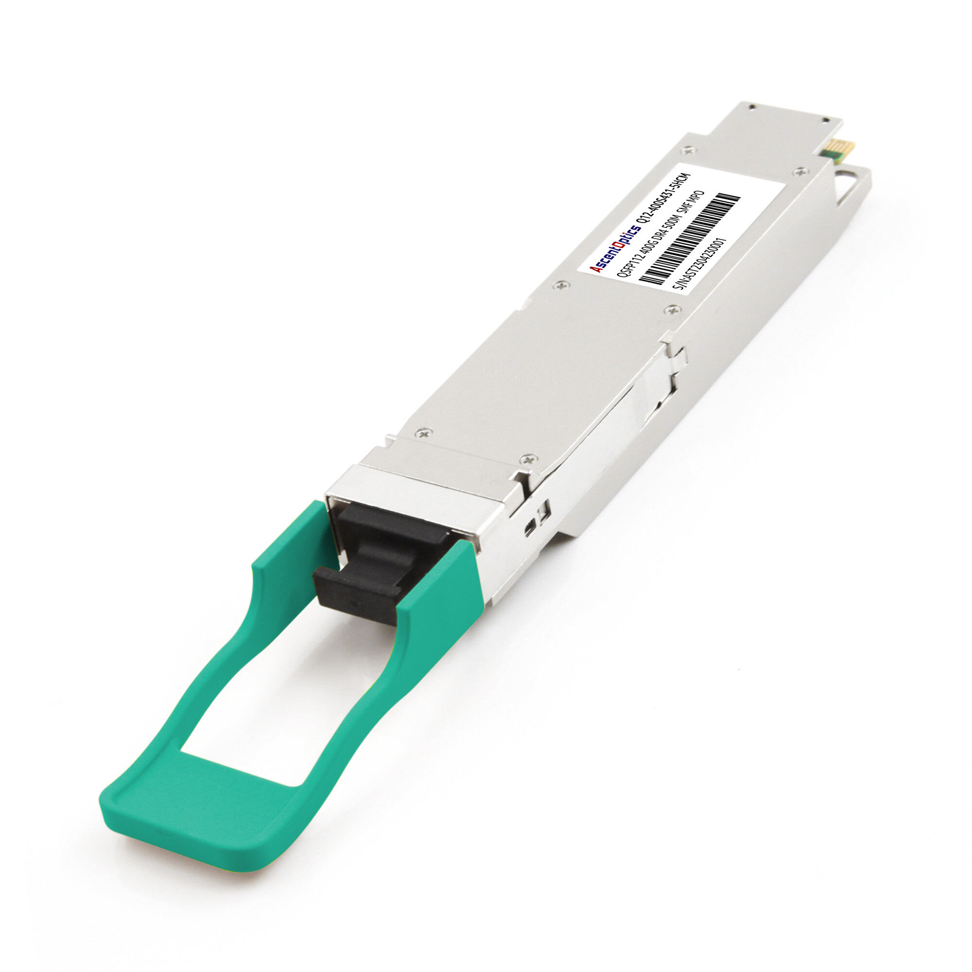
| DR4 |
OS2 |
MPO-12 APC |
500m |
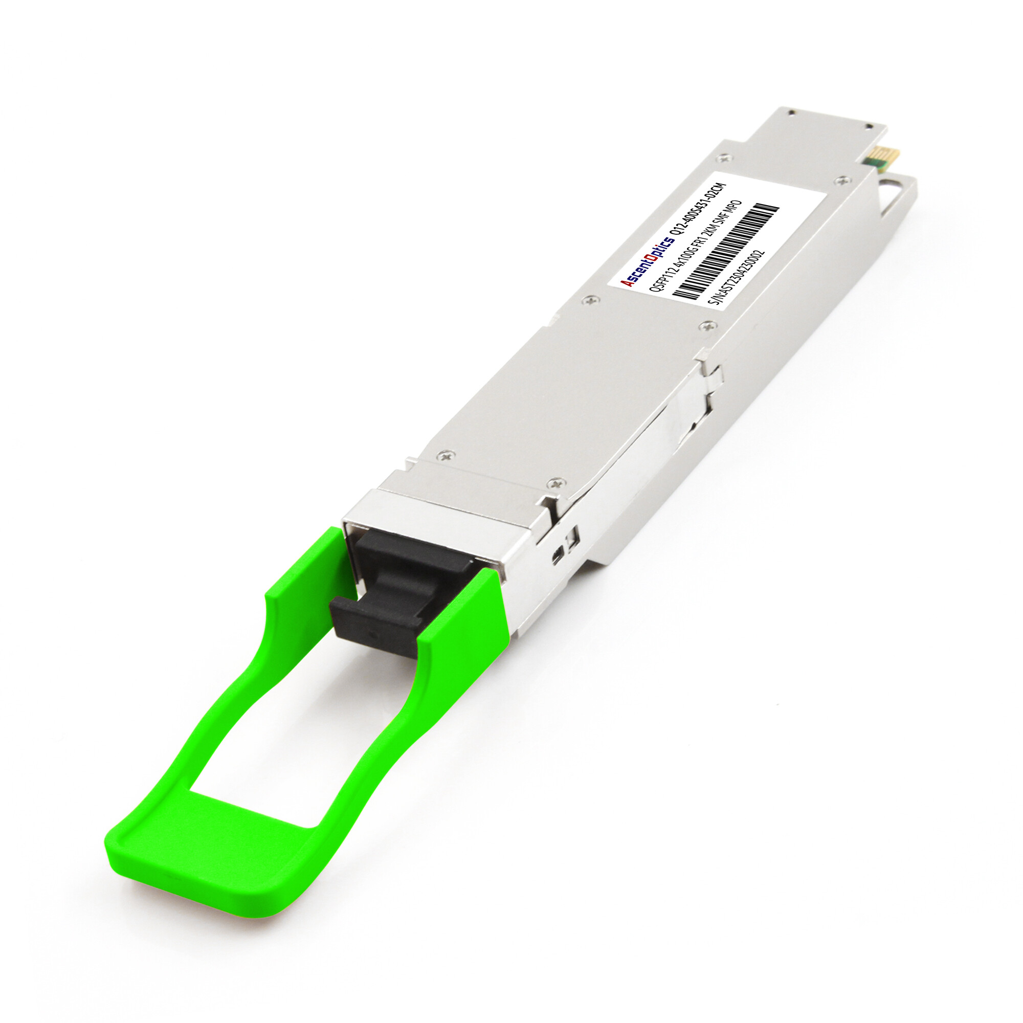
| 4x100G FR1 |
OS2 |
MPO-12 APC |
2km |
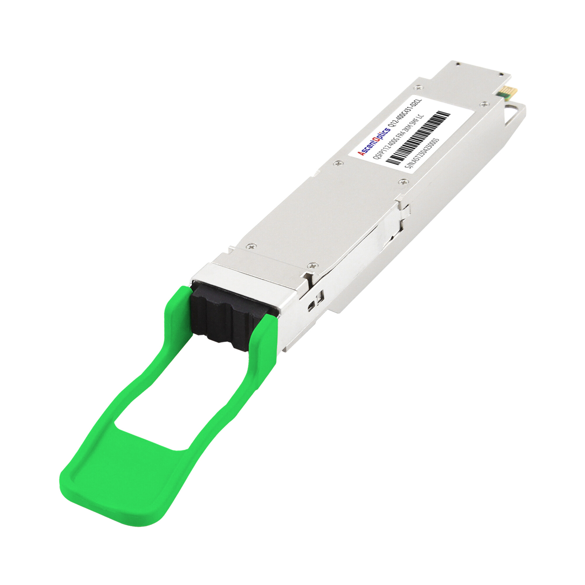
| FR4 |
OS2 |
Duplex LC |
2km |
| LR4 |
OS2 |
Duplex LC |
10km |
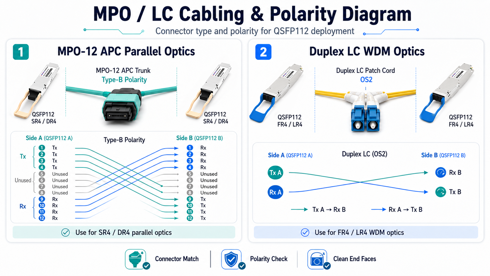
For parallel optics using MPO-12 APC connectors, validate fiber polarity. Type-B polarity is the most commonly deployed configuration for QSFP112 SR4 and DR4 links, although actual polarity design should follow the data center cabling architecture. A polarity mismatch will cause Tx/Rx lane misalignment and complete link failure.
Additionally, inspect the fiber plant for physical damage, excessive bend radius, and connector cleanliness. A single contaminated MPO ferrule can introduce insertion loss that exceeds the module’s power budget.
Power and Thermal Budgeting
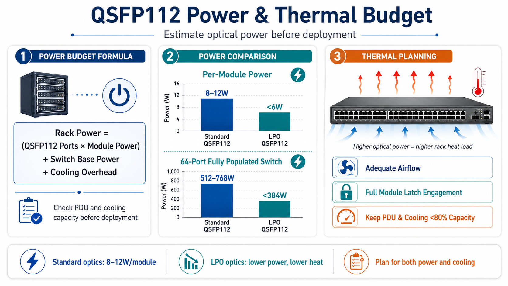
QSFP112 modules consume 8W to 12W per module under standard operation. LPO variants draw less than 6W. At rack scale, these numbers multiply quickly.
Calculate the total power budget using this formula:
Rack power = (Number of QSFP112 ports x Module power) + Switch base power + Cooling overhead
For example, a 64-port switch fully populated with standard QSFP112 modules will add approximately 512W to 768W of optical transceiver power alone. LPO modules would reduce this to under 384W. Ensure your rack PDU and cooling infrastructure can handle the combined load without exceeding 80% capacity.
Thermal management also requires attention. QSFP112 modules rely on direct metal contact between the module heat sink and the switch cage for heat dissipation. Verify that your switch platform provides adequate airflow and that the module latches engage fully to ensure thermal conductivity.
QSFP112 Module Selection by Deployment Scenario
Selecting the correct optical transceiver module depends on transmission distance, fiber type, and network topology. The following framework matches common deployment scenarios to the appropriate QSFP112 variant.
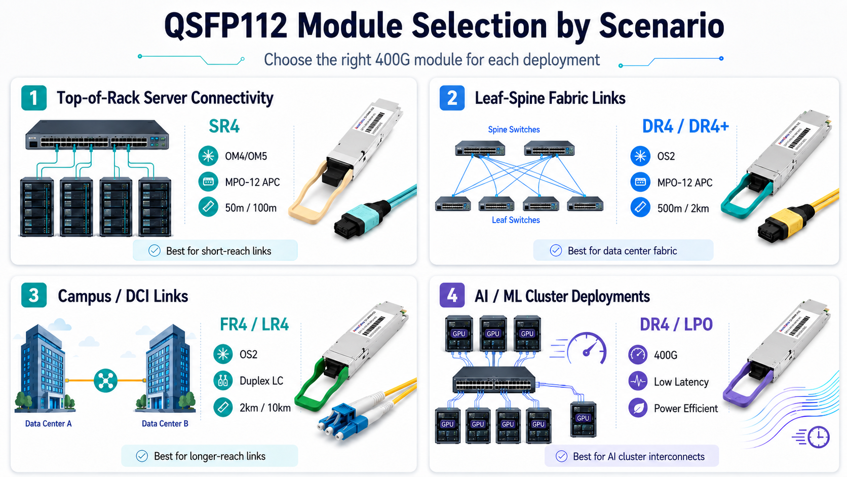
Top-of-Rack Server Connectivity
Top-of-Rack deployments typically require short-reach connectivity between servers and the access switch. For distances under 50 meters over multimode fiber, the 400GBASE-SR4 module is the standard choice. It uses MPO-12 APC connectors and supports 50 meters over OM4 or 100 meters over OM5.
Leaf-Spine Fabric Links
Leaf-spine architectures in modern data centers require medium-reach single-mode connectivity. The 400GBASE-DR4 module supports 500 meters over OS2 fiber using MPO-12 APC connectors. For extended reach up to 2 kilometers, the DR4+ variant provides additional power budget for longer fiber runs.
DR4 modules also support breakout configurations, allowing a single 400G port to connect to four 100G QSFP28 ports. This capability is essential during phased upgrades where legacy equipment must interoperate with new 400G infrastructure.
Campus and DCI Links
For campus networks and data center interconnects requiring 2-kilometer reach, the 400GBASE-FR4 module uses duplex LC connectors and CWDM wavelengths over a single fiber pair. For distances up to 10 kilometers, the 400GBASE-LR4 module provides extended reach with the same duplex LC interface.
AI and ML Cluster Deployments
AI training clusters demand high bandwidth and low latency. QSFP112 DR4 modules are widely deployed in NVIDIA Quantum-2 InfiniBand fabrics and Ethernet-based GPU clusters. Quantum-2 platforms use 400Gb/s NDR InfiniBand links based on 4×100G PAM4 lanes, making QSFP112 one of the dominant optical interfaces for large-scale AI clusters. For latency-sensitive workloads, LPO modules can reduce optical module latency by approximately 70–100ns compared with DSP-based optics.
When deploying QSFP112 in AI clusters, verify that your NICs and switches support the required InfiniBand or Ethernet application codes through CMIS application selection.
Physical Installation and Cabling
Proper physical installation protects both the optical transceiver module and the host equipment. Rushed insertions cause bent pins, damaged latches, and ESD failures.
Insertion Best Practices
Before handling any optical module, ground yourself using an ESD wrist strap. QSFP112 modules contain sensitive electro-optical components that can be damaged by static discharge.
Align the module with the cage carefully. The QSFP112 form factor includes a keyed housing that prevents incorrect orientation. Apply gentle, even pressure until the bottom latch clicks into place. Do not force the module if resistance is encountered.
After insertion, verify that the pull tab moves freely and that the module sits flush with the cage faceplate. A partially seated module will not make proper thermal contact and may overheat during operation.
Cable Installation
For MPO-12 APC connections, use a fiber tester to confirm polarity before connecting to the module. Label both ends of the cable clearly to prevent cross-connections during maintenance.
For duplex LC connections on FR4 and LR4 modules, ensure the transmit and receive fibers are correctly oriented. A simple Tx/Rx swap is one of the most common causes of link failure on WDM modules.
When using DAC or AOC cables, observe minimum bend radius specifications. Excessive bending degrades signal integrity in copper cables and can damage internal fibers in active optical cables.
CMIS Configuration and Breakout Setup
Modern QSFP112 modules use the Common Management Interface Specification (CMIS) to communicate with host platforms. Understanding CMIS application selection and breakout configuration is essential for successful deployment.
CMIS 4.0 and 5.x Application Selection
QSFP112 modules support multiple application codes that define the electrical and optical interface configuration. The host platform selects the active application using the Application Select (APSEL) register.
Common application codes for QSFP112 include:
- •400GAUI-4 C2M: 400G Ethernet over four lanes
- •400G InfiniBand: High-performance computing interconnect
- •100GAUI-1 C2M: 100G breakout lane configuration
400G to 4x100G Breakout Configuration
Breakout mode allows a single QSFP112 port to operate as four independent 100G links. This configuration requires support from both the module and the switch ASIC.
To configure breakout mode:
- 1. Verify switch firmware supports port bifurcation for QSFP112.
- 2. Select the breakout application code via CMIS APSEL.
- 3. Connect an MPO-12 to a 4x duplex LC harness cable for optical breakout.
- 4. Configure each breakout channel independently in the switch management interface.
FEC and Link Training
400G links rely on Reed-Solomon Forward Error Correction (RS-FEC 544,514) to maintain signal integrity at 112G PAM4. Both endpoints must use matching FEC modes. A mismatch will cause link flapping or persistent errors.
Link training calibrates the SerDes equalization settings for the specific cable and module combination. Enable link training during initial deployment, especially when using passive DAC cables or long fiber spans.
LPO QSFP112 Deployment Considerations
Linear Pluggable Optics (LPO) modules are entering widespread production in 2026. These modules remove the digital signal processor (DSP) chip, reducing power consumption and latency. However, LPO deployment introduces unique constraints.
When to Choose LPO
LPO QSFP112 modules are ideal for two scenarios. First, power-constrained racks where every watt matters. Second, latency-sensitive AI clusters where sub-60-nanometer latency provides measurable performance gains.
Industry testing has demonstrated that LPO architectures can significantly reduce module power consumption while lowering optical path latency compared with DSP-based designs.
Host Signal Integrity Requirements
LPO modules shift the signal compensation burden from the module DSP to the host ASIC. This means the switch or NIC must provide pre-emphasis and equalization capable of driving 112G PAM4 signals through the cable plant.
Before deploying LPO, confirm that your switch vendor has validated linear-drive operation with your specific module supplier. Interoperability testing is essential because LPO modules do not include the onboard DSP that normally compensates for signal degradation.
Reach and Environment Limits
LPO modules are designed for intra-data-center use only. The maximum reach is typically shorter than DSP-based equivalents, and performance depends heavily on fiber quality. Deploy LPO only in environments with clean, low-loss fiber plants and controlled temperatures.
Post-Deployment Validation
Installation is not complete until the link is validated under production-like conditions. A structured validation protocol catches intermittent issues before they affect live traffic.
DOM and Telemetry Verification
Digital Optical Monitoring (DOM) provides real-time visibility into module health. After establishing the link, verify the following parameters via the switch CLI or management interface:
- •Tx power: Within vendor-specified range for the module variant
- •Rx power: Within acceptable range for the fiber length and type
- •Temperature: Below 70 °C under steady-state operation
- •Voltage: Within 3.3V tolerance
Alarms for any of these parameters indicate a physical layer problem. Address the root cause before declaring the deployment complete.
Link Stability Burn-In
Run a 24-hour to 48-hour traffic test at production load levels. This burn-in period reveals thermal issues, intermittent FEC errors, and cable stress problems that do not appear during brief connectivity tests.
Monitor CRC errors, FEC symbol errors, and link flaps throughout the burn-in. A healthy QSFP112 link should show zero CRC errors and minimal FEC corrections under normal conditions.
Common Issues and Troubleshooting
| Symptom |
Likely Cause |
Resolution |
| Module not detected |
Firmware incompatibility |
Update switch firmware or verify CMIS support |
| Link up, but high CRC errors |
FEC mismatch |
Verify matching FEC mode on both endpoints |
| Intermittent link flaps |
Dirty fiber or loose connector |
Clean and reseat fiber connectors |
| High module temperature |
Poor thermal contact |
Reseat the module and verify latch engagement |
| Breakout lanes are not aligning |
Incorrect APSEL or polarity |
Check the CMIS register and MPO polarity |
Conclusion
Deploying QSFP112 transceivers successfully requires more than simply matching a module to a switch port. Network engineers must verify host platform compatibility, validate fiber infrastructure, calculate power and thermal budgets, configure CMIS applications correctly, and perform comprehensive post-deployment testing.
As 400G networking continues to expand across cloud data centers, AI clusters, and high-performance computing environments, QSFP112 has become one of the most important optical interfaces for next-generation infrastructure. Whether deploying SR4 for short-reach connectivity, DR4 for leaf-spine fabrics, or FR4 and LR4 for longer-distance links, following a structured deployment checklist helps minimize downtime, reduce troubleshooting effort, and ensure long-term network reliability.
For organizations planning large-scale 400G rollouts, careful attention to compatibility, cabling architecture, FEC configuration, and thermal management can significantly improve deployment success rates and operational efficiency. By applying the best practices outlined in this guide, engineers can build scalable, high-performance QSFP112 networks that are ready for the growing demands of AI, cloud, and data center applications.
Explore our QSFP112 product portfolio or contact our technical team for deployment guidance and compatibility recommendations.
Frequently Asked Questions
Q1: Can QSFP112 modules be used in QSFP28 ports?
No. Although QSFP112 and QSFP28 share the same physical dimensions, QSFP112 relies on 112G PAM4 electrical lanes while QSFP28 uses 25G NRZ signaling. The two interfaces are not electrically compatible.
Q2: During QSFP112 400G link initialization, what optical power parameters should be checked?
Ensure that the transmit optical power and the receive optical power fall within the range of the module’s nominal threshold. The attenuation loss of the single-mode/multimode fiber needs to be tested. In long-distance applications, it is important to test the cleanness of the fiber end face and the splice loss.
Q3: When configuring a 400G QSFP112 service, how do you verify the rate and negotiation mode?
Make sure that the port locks up at 400G rate and disables autonegotiate on speed reduction; verify that the code for the encoding method used is QSFP112, disable port FEC adaptive abnormal configuration, and ensure that the FEC error correction level matches the device.
Q4: During post-deployment stability checks, which operating parameters of the QSFP112 module should be checked?
Monitor the temperature, supply voltage, and bias current of the module; verify the port CRC error packets, bit error rate, and packet loss ratio statistics; monitor the long-term operating temperature, and set the speed of the chassis fan if the temperature is above threshold.
Q5: What are the specific checkpoints for QSFP112 400G in terms of cabling and physical links?
Verify the cables are QSFP112 dedicated cables/fiber optic patch cables, and check that the bending radius conforms to the specifications of the manufacturer; keep away from high-voltage cables which can cause parallel interference; observe proper antistatic procedures while inserting or removing power supplies; disable incompatible adapters.
Q6: How can I reduce power consumption in large QSFP112 deployments?
Consider using LPO (Linear Pluggable Optics) modules, optimizing airflow design, and selecting switches with high-efficiency cooling architectures.
Post Views: 20