100G SR4 Explained: Reach, Fiber, MPO Cabling, Applications, and Compatibility
June 15, 2023
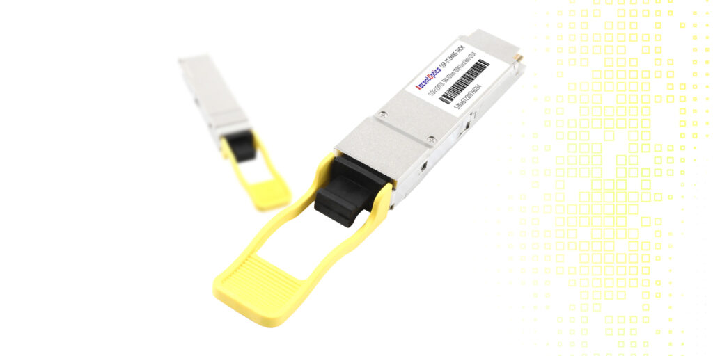
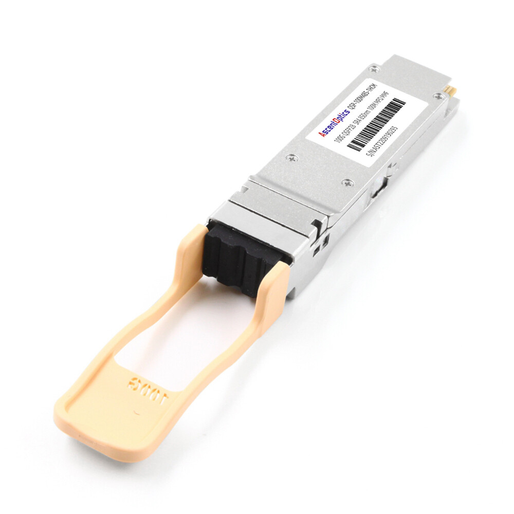
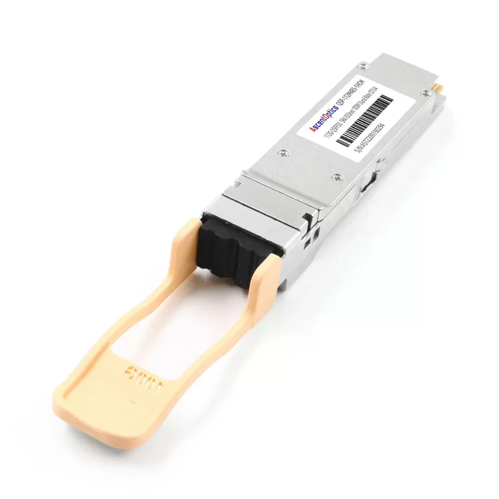
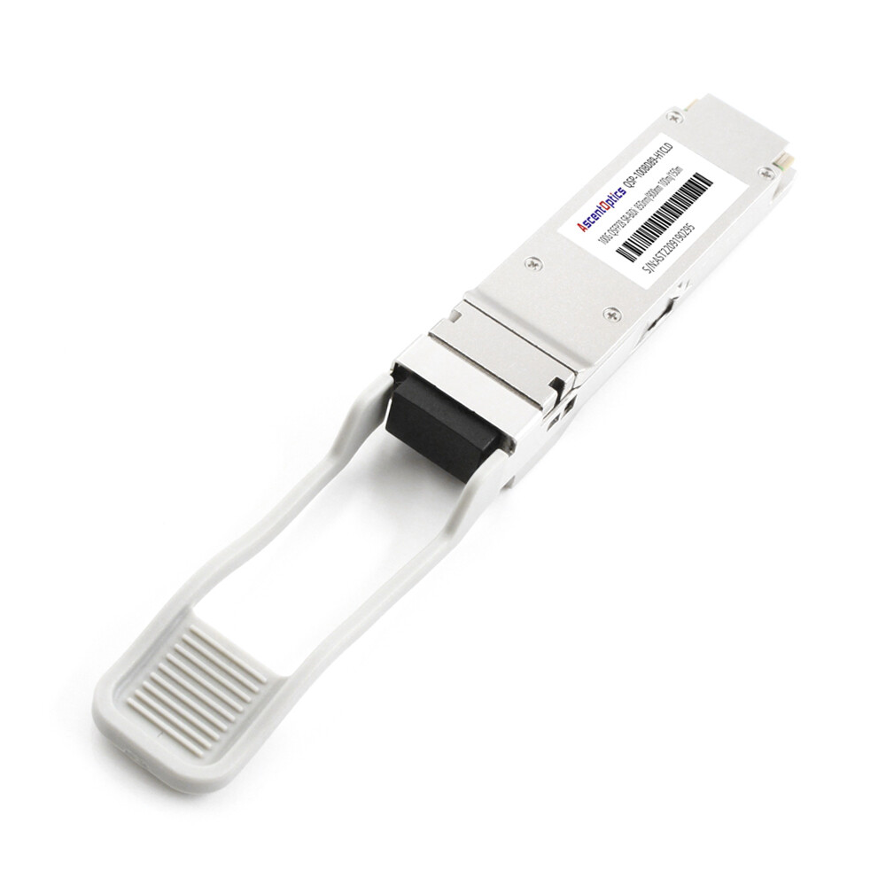
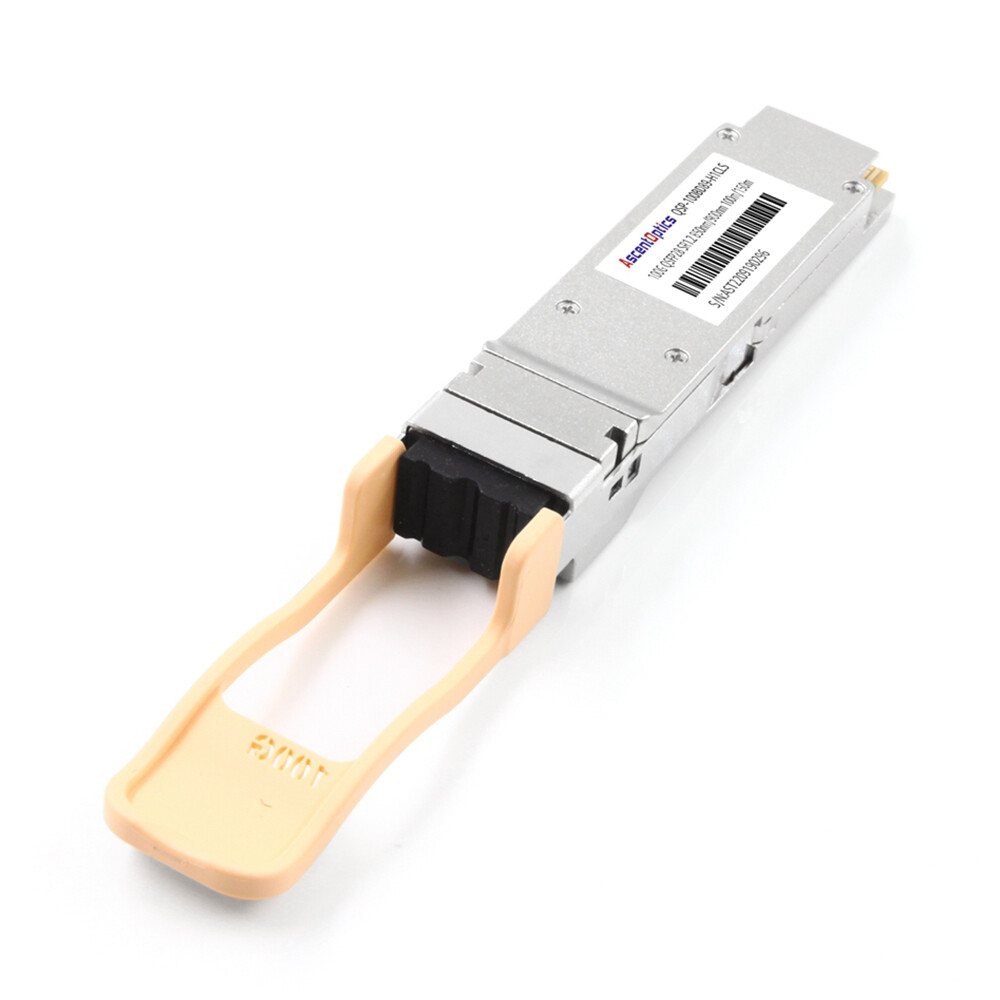
100G SR4 is one of the most widely deployed optical interfaces for short-reach 100 Gigabit Ethernet. It combines the compact QSFP28 form factor with four parallel 25G NRZ optical lanes at 850 nm, making it a cost-effective choice for high-density links inside data centers. A standard 100GBASE-SR4 connection reaches up to 70 meters over OM3 multimode fiber or 100 meters over OM4.
This guide explains how a 100G SR4 QSFP28 transceiver works, which cables and connectors it requires, where it is best used, how it compares with other 100G optics, and what to check before deployment.
A 100G SR4 transceiver is a short-reach, parallel-optics module for 100 Gigabit Ethernet over multimode fiber. The name can be read as follows: “100G” indicates a 100 Gb/s Ethernet interface, “SR” means short reach, and “4” refers to four optical lanes in each transmission direction.
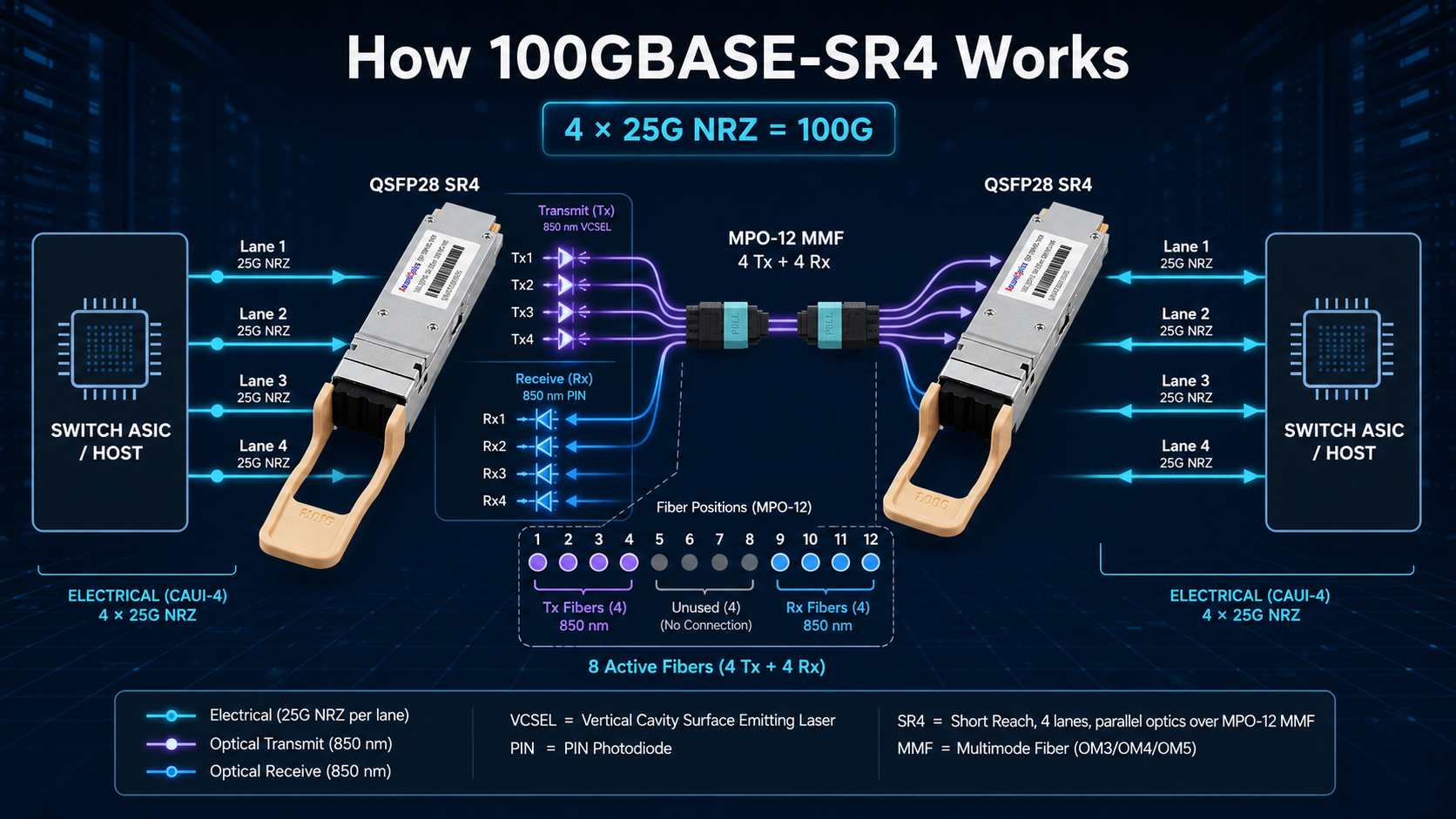
Unlike wavelength-multiplexed modules such as 100G CWDM4 or LR4, 100GBASE-SR4 does not combine multiple wavelengths onto a duplex fiber pair. Instead, it sends four independent 25G NRZ channels over four transmit fibers and receives four channels over four additional fibers. The link therefore uses eight active fibers inside a 12-fiber MPO interface.
100G SR4 at a Glance
Specification
Typical 100GBASE-SR4 Value
Ethernet specification
100GBASE-SR4, introduced by IEEE 802.3bm and incorporated into the current IEEE 802.3 standard
Form factor
QSFP28, hot-pluggable
Host electrical interface
Four 25.78125 Gb/s NRZ lanes, commonly described as 4 x 25G
Optical architecture
Four transmit lanes and four receive lanes in parallel
Nominal wavelength
850 nm near-infrared
Fiber type
OM3 or OM4 multimode fiber
Connector
MTP/MPO-12; eight fibers are active and four central positions are unused
Maximum reach
70 m over OM3; 100 m over OM4
Typical transmitter
850 nm VCSEL array
Typical power and temperature
Often below 3.5 W and 0 to 70 degrees C for commercial modules; verify the vendor datasheet
Note: Power consumption, operating temperature, alarm thresholds, and vendor coding are product-specific. Always confirm the actual transceiver datasheet and platform compatibility list.
How 100GBASE-SR4 Works
On the host side, a switch ASIC or network adapter presents four electrical lanes at approximately 25.78125 Gb/s per lane. Inside the QSFP28 module, a four-channel VCSEL array converts those electrical signals into four parallel 850 nm optical signals. At the far end, a matching receiver array converts the four optical lanes back into electrical signals and delivers them to the host.
1.The host sends four 25G-class NRZ electrical lanes to the QSFP28 module.
2. The module drives four 850 nm VCSEL transmitters, one for each optical lane.
3. The MPO-12 cable carries four transmit lanes and four receive lanes in parallel.
4. The receiving module converts the optical signals back to four electrical lanes.
5. The host PCS combines the lanes into a single 100 Gigabit Ethernet interface.
Because all four optical channels operate in parallel, lane alignment, FEC settings, fiber polarity, and optical loss must all be correct for a stable link.
MPO-12 Cabling, Fiber Count, and Polarity
Standard 100GBASE-SR4 uses an MTP/MPO-12 interface rather than a duplex LC connector. Although the connector contains 12 fiber positions, only eight are active: four transmit fibers and four receive fibers. The four center positions are normally unused.
For a direct SR4-to-SR4 link, verify all of the following:
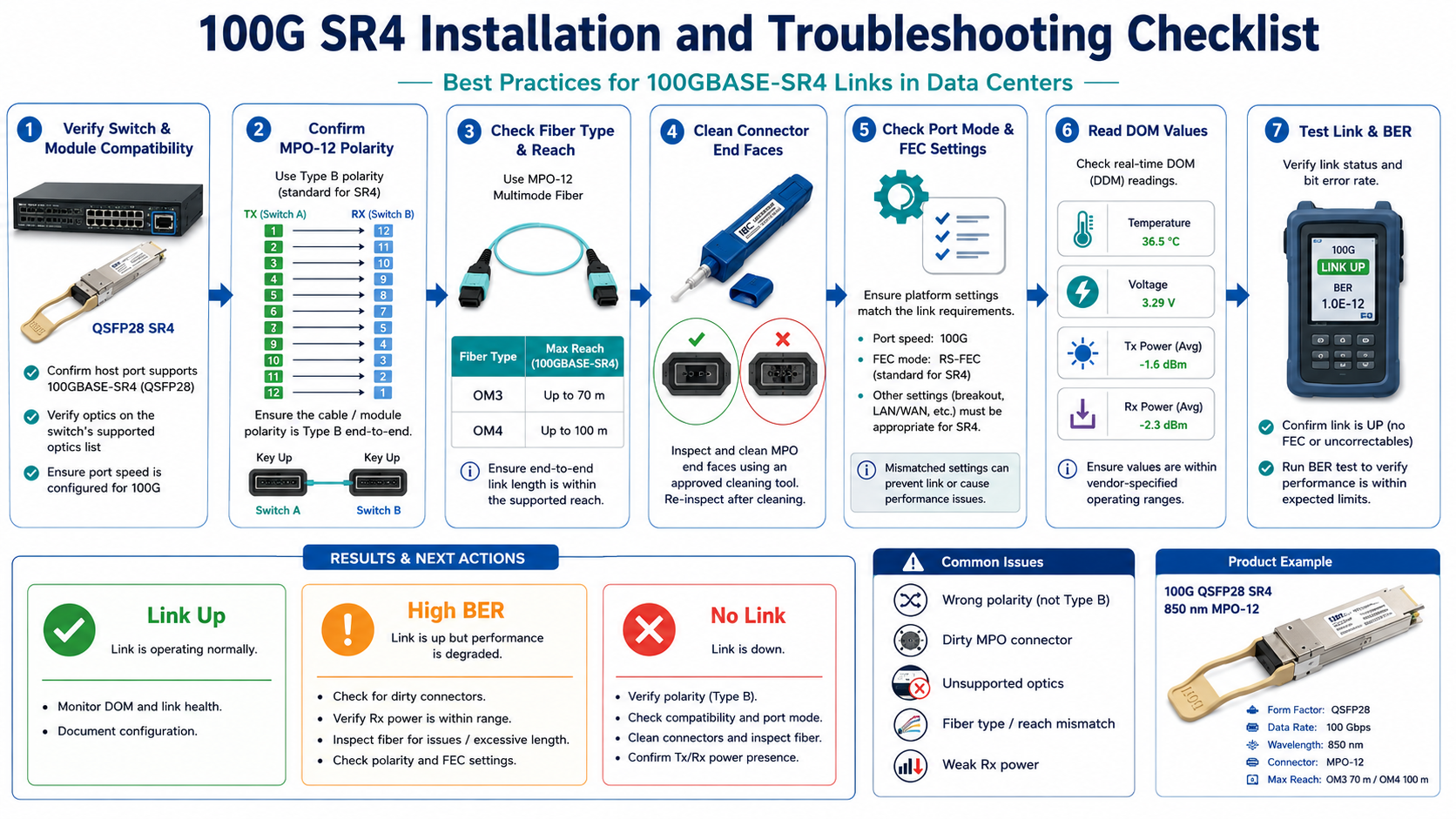
The patch cord is designed for parallel 100G SR4 service and uses the required MPO-12 polarity, commonly Type B for direct connections.
The connector pin and gender arrangement matches the transceiver and adapter system.
Both ends use OM3 or OM4 multimode fiber, not single-mode fiber.
Every MPO end face is inspected and cleaned before insertion.
The total channel loss, including connectors, adapters, and trunks, stays within the optical budget.
A duplex LC patch cord cannot plug directly into a standard 100G SR4 module. LC connectivity is possible only when using a supported MPO-to-4 x duplex LC breakout assembly, or when selecting a different 100G optic designed for duplex fiber.
100G SR4 Reach over OM3 and OM4 Fiber
The standardized maximum reach is 70 meters over OM3 multimode fiber and 100 meters over OM4 multimode fiber. OM4 supports the longer distance because its higher effective modal bandwidth reduces modal dispersion at 850 nm.
Fiber Type
Maximum Reach
Connector
Typical Use
OM3 MMF
70 m
MTP/MPO-12
Existing short-reach multimode infrastructure
OM4 MMF
100 m
MTP/MPO-12
New data center builds and longer in-row links
Longer operation may be possible with vendor-specific extended-reach optics, but those products are not standard 100GBASE-SR4. For example, 100GBASE-ESR4 modules may support substantially longer multimode links and must be qualified separately.
Best Applications for 100G SR4
100G SR4 is best suited to short, high-density connections where multimode fiber is already available or where the lower transceiver cost justifies deploying parallel-fiber cabling.
Switch-to-Switch Links
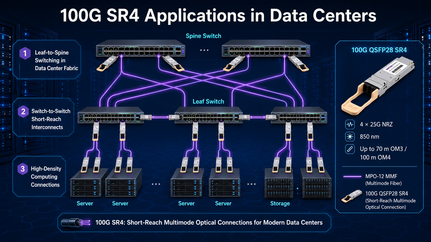
SR4 is commonly used between leaf and spine switches, top-of-rack and end-of-row switches, or adjacent network devices within the same data hall. OM4 provides enough reach for most in-row and many cross-row connections.
Switch-to-Server and Storage Links
Servers, storage platforms, and appliances equipped with 100G QSFP28 ports can connect directly to switches using a pair of compatible 100G SR4 modules and an MPO-12 multimode cable.
100G-to-4 x 25G Breakout
A 100G SR4 port can often be divided into four independent 25G links using an MPO-12 to 4 x duplex LC breakout cable. This application requires the switch port to support 4 x 25G breakout mode and the remote devices to use compatible 25GBASE-SR optics. FEC and lane mapping must be configured according to the platform requirements.
High-Performance Computing and Cloud Networks
The low latency, compact form factor, and high port density of QSFP28 SR4 make it useful in HPC clusters, cloud fabrics, storage networks, and other east-west traffic environments where link lengths remain below 100 meters.
100G SR4 vs PSM4, CWDM4, and LR4
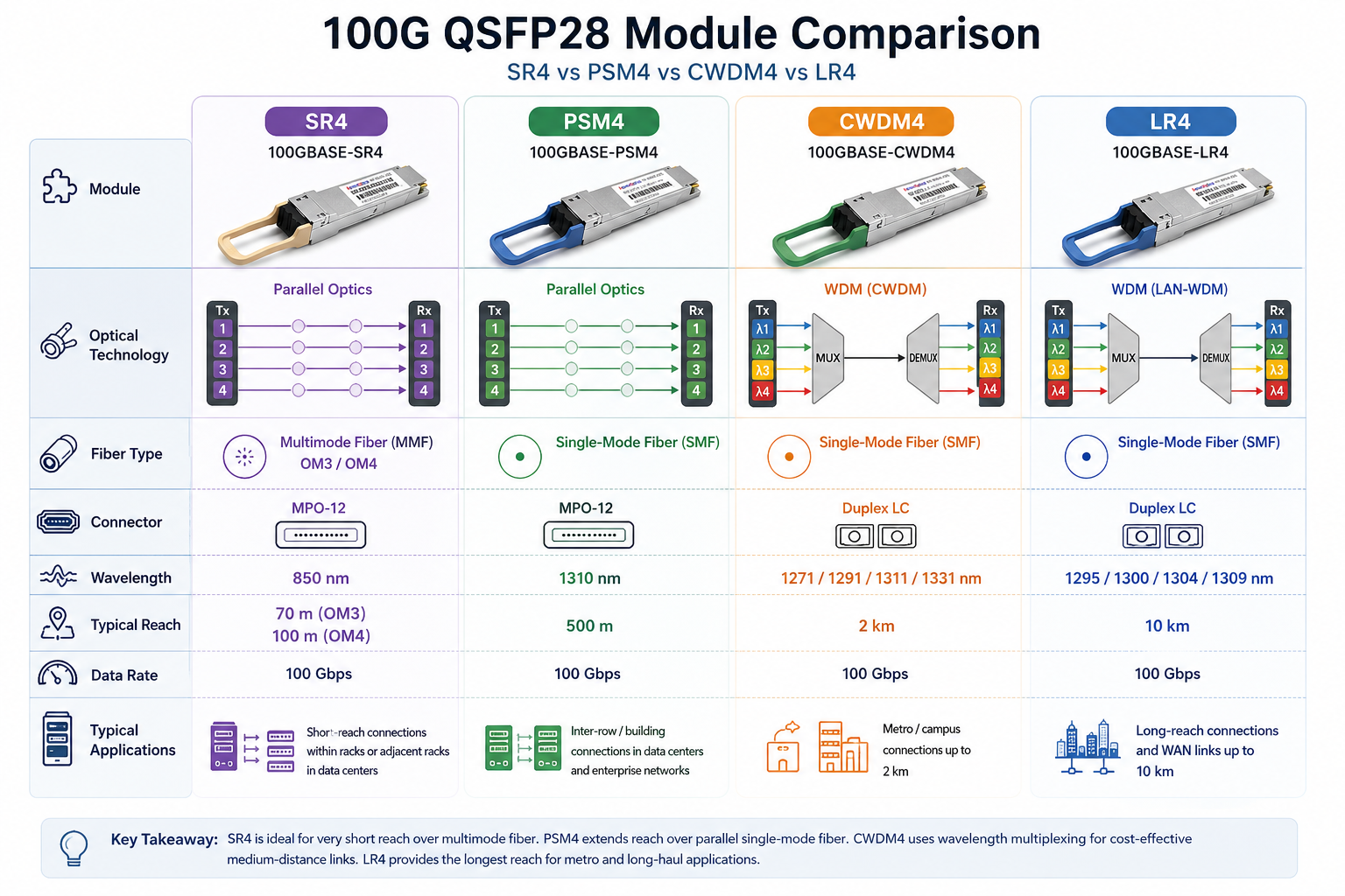
The best 100G QSFP28 optical transceiver depends primarily on link distance, installed fiber infrastructure, connector preference, and overall deployment cost. 100G SR4 is typically the preferred choice for links up to 100 meters in high-density data centers using multimode fiber. For longer distances over single-mode fiber, PSM4 offers a cost-effective parallel optics solution, while CWDM4 reduces fiber count by transmitting over a duplex LC interface. LR4 is designed for campus and metro enterprise networks where transmission distances of up to 10 km are required.
A module that physically fits a QSFP28 port is not automatically guaranteed to link. The host platform must support 100G operation, the selected transceiver type, the required FEC mode, and any breakout configuration.
Forward Error Correction
100GBASE-SR4 commonly uses host-based IEEE RS-FEC, also known as Clause 91 FEC. Many switches enable it automatically, while others expose explicit FEC settings. A mismatch between the two link ends can prevent the link from coming up or can create a high error rate. Follow the switch or NIC documentation and keep both ends configured consistently.
Vendor Coding and Platform Qualification
Some switches accept standards-compliant third-party optics without restriction, while others check module EEPROM coding, firmware versions, or approved part numbers. A claim such as “Cisco compatible” should therefore refer to a specific switch family and software release rather than to Cisco equipment in general.
Breakout Support
Breakout requires more than an MPO-to-LC cable. The host port must support 4 x 25G operation, the lanes must map correctly, and the remote interfaces must support the corresponding 25G signaling and FEC mode.
Digital Optical Monitoring (DOM)
Most modern 100G SR4 QSFP28 modules provide digital optical monitoring through the module management interface. Depending on the implementation, the host can read module temperature, supply voltage, laser bias current, and transmit and receive optical power for individual channels.
DOM helps operators:
Identify low receive power caused by dirty connectors, excessive loss, or a damaged fiber lane.
Detect abnormal temperature or supply voltage before a link fails.
Compare optical power across the four lanes and isolate lane-specific problems.
Set warning and alarm thresholds in network monitoring systems.
DOM does not measure ambient light, and a normal DOM reading does not replace connector inspection or an end-to-end link-loss test.
Installation and Troubleshooting Best Practices
Before installation:
Inspect and clean every MPO connector using tools designed for multifiber ferrules.
Keep dust caps installed until the connection is ready to be made.
Avoid excessive cable bends, twists, and tensile stress.
Label polarity and link endpoints clearly to reduce deployment errors.
When the link does not come up:
Verify that both ports are configured for 100G rather than 40G, 4 x 25G, or another breakout mode.
Check FEC settings on both ends.
Confirm module coding and platform support.
Verify the MPO polarity and lane mapping.
Inspect and clean both connectors, then reseat the modules.
Read DOM data and look for a weak or missing receive lane.
Test the cable plant for insertion loss and damaged fibers.
Conclusion
100G SR4 remains a practical and economical solution for short-reach 100 Gigabit Ethernet. Its four-lane 850 nm architecture delivers 70 meters over OM3 or 100 meters over OM4, while the QSFP28 form factor supports high port density and straightforward 4 x 25G breakout.
Successful deployment depends on more than selecting two SR4 modules. The fiber type, MPO polarity, connector cleanliness, FEC configuration, host support, vendor coding, and thermal limits must all be checked. When those details are controlled, 100GBASE-SR4 provides a reliable, low-latency connection for modern data center, cloud, storage, and HPC networks.
Frequently Asked Questions
Can 100G SR4 reach 100 meters?
Yes. A standards-based 100GBASE-SR4 link supports up to 100 meters over OM4 multimode fiber. The maximum standardized reach over OM3 is 70 meters.
Does 100G SR4 use LC connectors?
No. Standard 100GBASE-SR4 uses an MTP/MPO-12 parallel-fiber interface. A breakout cable can fan the MPO interface out to four duplex LC connections for 4 x 25G operation, but a duplex LC patch cord cannot connect directly to a standard SR4 module.
Can 100G SR4 run over single-mode fiber?
No. 100GBASE-SR4 is designed for OM3 or OM4 multimode fiber at 850 nm. For single-mode fiber, consider PSM4, CWDM4, DR, FR, LR4, or another optic that matches the required reach and host platform.
How many fibers does 100G SR4 use?
It uses eight active fibers: four transmit fibers and four receive fibers. These are presented through a 12-fiber MPO interface, with the four central positions normally unused.
Can a 100G SR4 module break out to four 25G links?
Often yes. The switch must support 4 x 25G breakout mode, and the link requires an MPO-12 to 4 x duplex LC breakout cable plus compatible 25G SR optics at the remote ends.
Is 100G SR4 compatible with 40G SR4?
Not automatically. The two technologies share a similar parallel-fiber concept and may use the same MPO cabling, but their electrical lane rates and Ethernet modes are different. Interoperation is possible only when the modules and host ports explicitly support the required dual-rate or breakout mode.
Is every third-party 100G SR4 module compatible with Cisco switches?
No universal claim is reliable. Compatibility depends on the exact Cisco platform, software release, EEPROM coding, FEC behavior, and supported optics policy. Use a module qualified for the specific device and verify the current interoperability information.
What does DOM monitor in a 100G SR4 module?
Typical DOM data includes module temperature, supply voltage, laser bias current, and transmit and receive optical power. Some hosts expose per-lane values and alarm thresholds.
What is the normal operating temperature of a 100G SR4 module?
Commercial-temperature modules commonly operate from 0 to 70 degrees C, but industrial and extended-temperature versions differ. Use the module datasheet and the host platform thermal guidelines as the final authority.
What is the difference between QSFP+ and QSFP28?
They belong to the same compact QSFP mechanical family, but QSFP28 supports higher per-lane electrical rates for 100G applications. QSFP28 is not simply a smaller version of QSFP+; compatibility depends on the host port and supported speed modes.