With the widespread use of mobile internet and and the Internet Of Thing, data center traffic is experiencing explosive growth. According to the Cisco’s Global Cloud Index report, as of 2020, cloud computing traffic has accounted for 92% of global data center traffic. Among them, hyper-scale data centers contributed 53% of global data center traffic. Hyper-scale data centers experience a nearly doubling of network bandwidth demand every one and a half to two years. Consequently, they upgrade their network systems, on average, every three years to meet the increasing data center traffic.
In China, hyper-scale data centers started deploying 40G Ethernet Hin 2014, followed by the development of 100G Ethernet in 2017. Following this timeline, Chinese hyper-scale data centers were expected to commence deploying 400G Ethernet in 2020. It was anticipated that around by 2022, 400G Ethernet would transition into the large-scale deployment phase.
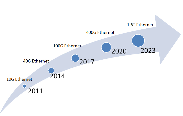
Figure 1 Evolution Path of Ultra-Large-Scale Data Center Networks in China
Construction of Optical Module
The composition of Optical Modules
The main function of an optical module is to achieve the mutual conversion of electrical-optical(E-O) signals and optical-electrical(O-E) signals. Optical modules are typically composed of optical components, circuits, optical interfaces, and electrical interfaces. Among them, the optical components include the receiver optical sub-assembly(ROSA), the transmitter optical sub-assembly(TOSA), and the bidirectional optical sub-assembly(BOSA).
In the circuit section, the optical module contains an emitting laser driver circuit, a receiver amplifier circuit, and a temperature monitoring/control circuit. Transmitter optical sub-assembly(TOSA) is mainly responsible for the electric-optical conversion function. It includes devices such as the laser driver(LDD), laser diode(LD), thermorelectric cooler(TEC), isolator, mux combiner and coupling lens.
The receiving optical sub-assembly(ROSA) is primarily responsible for the optical-electrical conversion function. Its composition includes a photodetector(PD), transimpedance amplifier(TIA) used in conjunction with the photodetector for signal amplification, demux splitter, and limiting amplifier(LA) that converts the amplified logic signal from a TIA into a digital signal.
In addition, the circuit is responsible for the direct current(DC) driving and signal modulation of the laser diode(Tx part). It also amplifies and processes signals from the photodetector(Rx part). The entire optical module is controlled by the MCU( Main Control Unit). The MCU performs logical control functions such as timing control, power control, temperature control, and alarm functions.
In summary, the optical module achieves the conversion between electrical-optical and optical-electrical signals through the collaborative work of optical components and circuits. The MCU provides effective logic control, ensuring the proper functioning and optimized performance of the optical module.
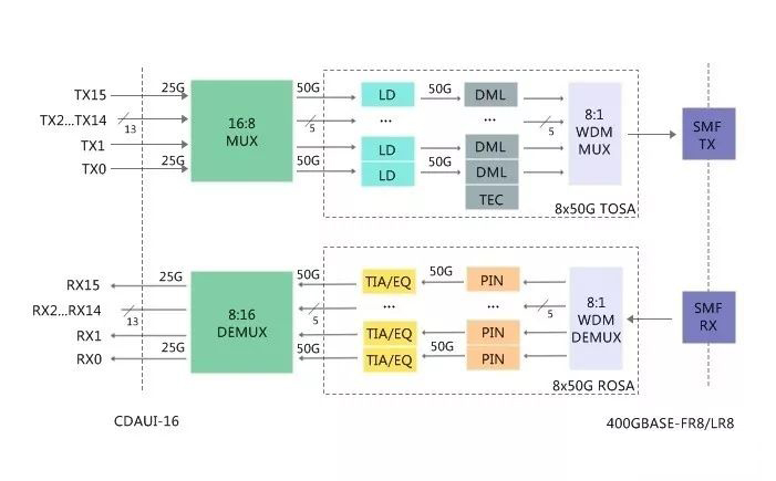
Figure 2 The main components of optical module
Classification of optical chips and electrical chips
In the optical module, the optical and electrical chips are the most critical components, accounting for approximately 80% of the module’s cost. The optical chips primarily consist of laser diode chips and photodetector chips. The electrical chips, on the other hand, encompass components such as CDR( Clock and Data Recovery), TIA transimpedance amplifiers, LA limiting amplifiers, LDD laser driver, and the MCU main controller.
Regarding laser chips, based on their emission method, they can be categorized as surface-emitting lasers is predominately led by VCSELs. VCSELs offers advantages such as compact size, high coupling efficiency, low power consumption, ease of integration, and cost-effectiveness.
As a result, they are commonly employed for short-distance applications in data centers. Edge emitting lasers encompass FP( Fabry-Perot) lasers and DFB (Distributed Feedback) lasers. FP lasers offer the advantages of higher output power and a smaller divergence angle. They are suitable for low-speed, mid-range applications such as distances within 10km. DFB lasers, built upon the foundation of FP lasers, incorporate a diffraction grating that allows for wavelength selection, achieving signal longitudinal mode output. DFB lasers offer benefits including higher output power, narrow spectral linewidth, low dispersion, high modulation rates, and longer transmission distances.
They are generally employed for high-speed applications within distances of up to 40km. For laser diode (LD) chips, based on their modulation methods, they can be categorized as Direct Modulation Lasers(DML) and External Modulation Lasers(EML). DML control their output intensity by varying the injected current, characterized by their small size and low power consumption. However, they have a small extinction ratio and higher chirp, making them generally suitable for applications within 10km.
EML are an extension of DML lasers that incorporate an Electro-Absorption Modulator (EAM). EAM modulates signal intensity through the electro-absorption effect. EML lasers offer high modulation rates, low jitter, minimal dispersion, high extinction ratio, low chirp, and ample eye diagram margin. However, compared to DML lasers, they have higher power consumption. To ensure the stability of the modulated signal, EML lasers typically require expensive TECs for cooling. As a result, EML lasers have higher costs and generally suitable for long-distance applications within 40km.
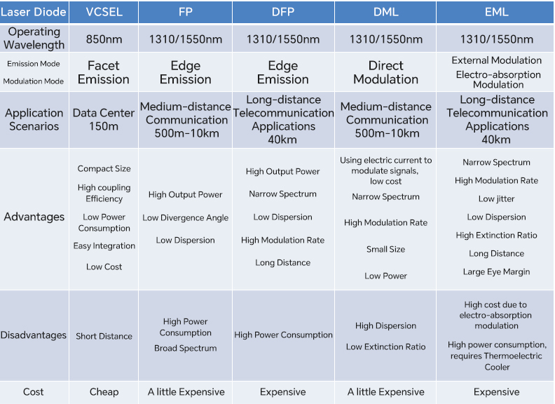
Figure 3 Classification of Lasers
The main role of the detector PD(Photodetector) chip in an optical module is to convert optical signals into electrical signals. In terms of detectors, there are two primary types: one is the Photodiode (PIN), and the other is the Avalanche Photodiode (APD). APD utilizes the avalanche multiplication effect to significantly enhance the sensitivity of signal reception. Due to its superior performance, APDs are commonly employed in scenarios that require longer distance transmission, such as distances exceeding 40km for long-distance transmission.
However, due to its complex structure and high-performance demands, APDs come with a significantly higher cost compared to PIN photodiodes. Therefore, in optical modules, considering the requirements and cost considerations, it is possible to select the appropriate detector type based on the scenario. For shorter distance transmissions, the more cost-effective option of a Photodiode(PIN) can be chosen. However, for longer distance transmissions, the higher sensitivity but more expensive option of an Avalanche Photodiode(APD) can be considered.
The Form Factor for 400G Optical Modules
The main metrics for data center optical modules include density, power consumption, and cost. Among them, thermal capacity is an important indicator that measures the power consumption of optical modules. A higher thermal capacity indicates that the optical module can handle greater power consumption.
Currently, 400G optical modules are primarily categorized into several types based on form factor, including CDFP, CFP8, QSFP-DD, and OSFP. CDFP and CFP8 have larger dimensions and higher thermal capacity, making them more suitable for the telecom market.
CDFP and CFP8 have larger dimensions and higher thermal capacity, making them more suitable for the telecom market. On the other hand, QSFP-DD is backward-compatible with the previous QSFP28, featuring a smaller size and higher density. As a result, QSFP-DD is better suited for short-distance transmission within data centers. It has gained widespread support from companies such as Facebook, Alibaba, and Tencent.
Another Type is the OSFP MSA, which has garnered support from companies like Google and Arista. The OSFP form factor is slightly larger than QSFP-DD. But in comparison to QSFP28, an additional adapter is required for the OSFP optical module to be compatible with the OSFP socket. OSFP also possesses the capacity to support backward compatibility up to 800G. Additionally, it comes equipped with its own heatsink capable of handling a thermal capacity ranging from 12 watts to 15 watts. As a result, OSFP is better suited for the telecommunications market.
In general, based on different requirements and application scenarios, one can choose optical modules with different form factor. Factors such as density, power consumption, and cost are all crucial elements that need to be comprehensively considered.

Figure 4 The form factor for 400G optical modules
400G Optical Module Naming Conventions
The IEEE 802.3 working group has defined a clear naming convention for optical modules. For instance, in the name “400G SR4.2”, each components carries the following meanings:
- “400G” represents a transmission rate of 400 gigabits per second (Gbps) for the optical module.
- The “S” indicates that this optical module is suitable for interconnections within data center equipment racks, with a typical transmission distance of up to 150 meters.
- The “4” represents the use of 4-core optical fibers, meaning there are four individual optical fibers used for data transmission.
- lThe “2”indicates that each individual optical fiber supports two wavelengths, allowing each fiber to simultaneously transmit two different wavelengths.
By using this naming convention, we can gain a clear understanding of key characteristics of the optical module such as its transmission rate, applicable scenarios, the number of optical fibers used, and the wavelengths it supports. This assists in making accurate selections and using optical modules effectively.
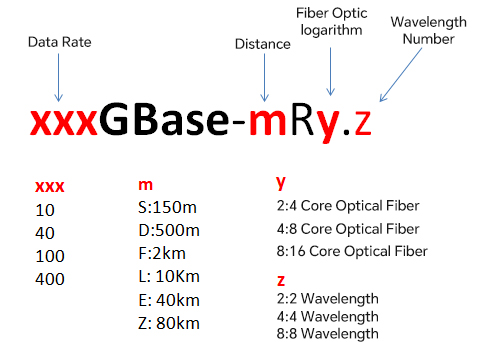
Figure 5 IEEE Optical Module Naming Conventions
“m” represents the Physical Medium Dependent sublayer (PMD) within the Ethernet standard. The PMD is responsible for taking the signals from the Physical Medium Attachment(PMA) layer and converting them into signals that can be transmitted over specific media. For example, copper cables, single-mode or multi-mode optical fibers. There are several types of PMD:
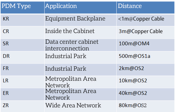
Figure 6 Types of optical modules
Comparison of 400G solutions for data centers
Data centers primarily encompass three main application scenarios, including:
1. Interconnection of Top-of-Rack switches and servers within cabinets:
In this scenario, Top-of-Rack switches are connected to servers to facilitate efficient communication among servers and between servers and switches.
2. Interconnection of Switches between cabinets:
Within data centers, switches in different cabinets need to be interconnected to establish large-scale and more flexible network architectures.
3. Data Center Interconnection(DCI):
This scenario involves connectivity between different data centers and is typically utilized for communication between data centers across geographical regions or cities to achieve resource sharing and backup.
By effectively configuring and interconnecting these three application scenarios, data centers can provide a high-performance and highly available network architecture. This architecture can effectively support diverse business requirements and application scenarios.

Figure 7 Data center application scenarios ( Source: C-Link)
Interconnection of Top-of-Rack switches and servers
In the interconnection between ToR switches and servers, there are two primary solutions, namely using direct attach copper(DAC) cables and active optical cables(AOC). As network speeds increase, the transmission distance of DAC becomes shorter. DAC can be further categorized into active copper cables (ACC) and passive copper cables(PCC). For instance, in a 40-0G connection, the maximum transmission distance for 400G PCC passive copper cables us 2.5 meters. The 400G ACC active copper cables can reach a maximum transmission distance of 5 meters.
The advantage of DAC lies in its cost-effectiveness. But it also has evident drawbacks, mainly manifesting in limited transmission distance, relatively bulky cables, and complex wiring. As data center server network speeds continue to increase and server density grows, DAC poses a significant challenge to the heat dissipation within server cabinets.
Another solution is AOC, which boasts several advantages, including lightweight design, extended transmission distances, electromagnetic interference (EMI) resistance, and easy installation. Theoretically, AOC can achieve a maximum transmission distance of up to 150 meters using multi-mode optical fibers. However, due to the presence of modules on both ends of AOC, it is not suitable for inter-cabinet deployment. Therefore, AOC is typically employed in scenarios where transmission distances are less than 30 meters.
In conclusion, the choice of interconnection solution between ToR switches and servers should be based on specific requirements. DAC is suitable for shorter distance connections, offering a relatively lower cost, but it may face challenges in terms of heat dissipation. On the other hand, AOC is suitable for longer distance connections, providing advantages in interference resistance and easy installation. However, it has limitations when it cones to inter-cabinet deployment.
Comparison of interconnected switch optical modules
Currently, there are four 400G solutions for interconnecting spine-leaf switches or leaf-TOR switches in data centers. Firstly, the 400G SR16 solution, due to its utilization of a higher number of optical fiber cores, is generally nit preferred by most users in large-scale data centers. Therefore, it will not be discussed further here.
400G SR8 Solution:
Looking at the cost perspective of optical modules, the next consideration is the 400G SR8 solution. This solution utilizes well-established 25G baud rate VCSEL laser chips available in the market and employs PAM4 pulse amplitude modulation technology. Currently, the 25G baud rate VCSEL laser chips are highly mature in the market. Thus making the cost of the 400G SR8 optical module the lowest.
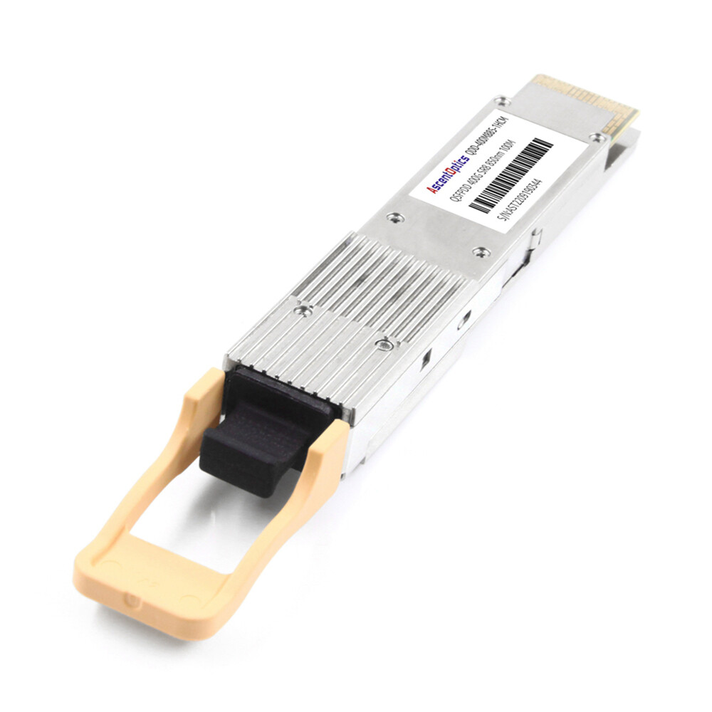
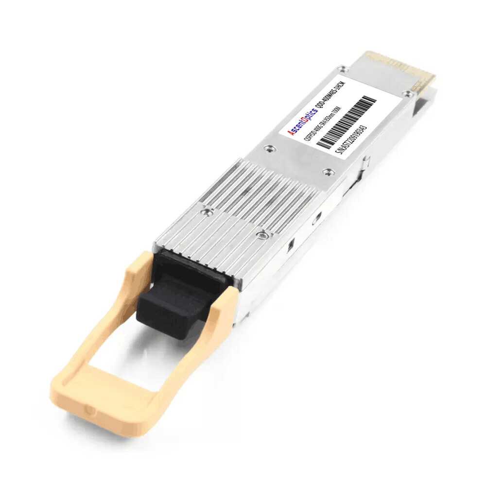
400G SR4.2 Solution:
On the other hand, the 400G SR4.2 optical module employs a dual-wavelength 25G baud rate VCSEL laser chip and requires a 2:1 mux combiner and 1:2 Demux splitter. This increases the cost of the optical module. Furthermore, the ecosystem for the 400G SR4.2 optical module is not as well-established. There are limited suppliers for the optical chips. As a result, the cost of the 400G SR4.2 optical module is notably higher than that of the 400G SR8 optical module.
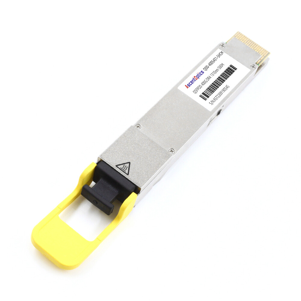
400G DR4 Solution:
Another option is the 400G DR4 optical module. It utilizes the relatively expensive DML (Distributed Feedback Laser) lasers or SiPh(Silicon Photonics) technology. Silicon Photonics technology enables the integration of conventional optical components like modulators and detectors onto a silicon substrate using complementary metal-oxide-semiconductor (CMOS) processes. This integration results in significant reductions in power consumption, size, and packaging costs of optical modules.
However, Silicon Photonics technology is currently in the early stages of industrial development, with relatively low shipment volumes. As a result, it has not yet achieved economies of scale. According to recent research reports by LightCounting, modules based on Silicon Photonics technology exhibit lower overall shipment volumes compared to traditional InP (Indium Phosphide) or GaAs (Gallium Arsenide) material-based optical modules.
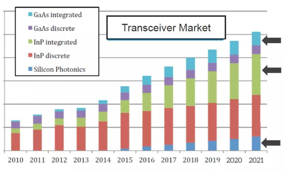
Figure 8 Comparison of market shares between traditional module and silicon photonics module(source: LightCounting)
Currently, mainstream switch ASIC chips typically employ 25G baud rate PAM-4 signals. While the 400G DR4 optical module utilizes 50G baud rate PAM-4 signals, translating to a single-wavelength 100Gbps transmission rate. In order to maintain consistency between switch electrical signals and optical module electrical signals, a gearbox needs to be incorporated within the 400G DR4 optical module. This gearbox is used to convert 8 channels of 50Gbps into 4 channels of 100Gbps. The addition of this gearbox results in increased costs and power consumption, making the 400G DR4 optical module the most expensive among these three solutions.
However, the 400G DR4 optical module is suitable for scenarios where switch interconnect distances range from 150 to 500 meters. Despite its higher cost, it holds an advantage in data center applications that require longer interconnect distances due to its support for extended transmission ranges. Therefore, when considering various application scenarios and requirements, selecting the appropriate optical module solution is crucial.

Figure 9 Schematic Diagram of 400G DR4 Gearbox (Source: Arista)
Cabling solutions for different 400G optical modules:
From a cabling perspective, different 400G optical module solutions utilize varying types of optical fibers and fiber connectors to meet the connectivity requirements of data centers.
For 400G DR4, it utilizes 8-core single-mode optical fibers for parallel transmission. Fiber optic connectors use the angled physical contact (APC) of 8 degrees, such as MPO/MTP-12 or MPO-MTP-8 connectors. These connectors effectively reduce return loss, minimize overall fiber link loss, and ensure the stability and reliability of data transmission.
For 400G SR4.2, it employs 8-core multi-mode optical fibers for parallel transmission, and the fiber connectors also utilize MPO/MTP-12 or MPO/MTP-8 connectors. On the other hand, 400G SR8 utilizes 16-core multi-mode optical fibers for parallel transmission. To reduce return loss, its fiber connector employs the MPO/MTP-16 connector with an angled physical contact (APC) end face of 8 degrees. The keying of the MPO/MTP-16 fiber connector is designed with offsets to prevent confusion with MPO/MTP-12 or MPO/MTP-8 connectors.
By carefully selecting the appropriate fiber types and connectors, data centers can implement efficient cabling solutions that ensure the performance and reliability of fiber optic transmission, meeting the connectivity requirements of various 400G optical module solutions.

Figure 11 MPO/MTP-16 Fiber Connector (Source: US CONEC)
For newly constructed data centers, to support 400G SR8 optical modules, it’s recommended to deploy an MPO/MTP-16 fiber cabling system directly catering to the requirements of 400G SR8 Ethernet applications. By utilizing the MPO/MTP-16 fiber cabling system, the demands of high-speed transmission can be met, enabling high-density and high-bandwidth network connections within the data center. This type of cabling system can provide suitable fiber pathways for 400G SR8 optical modules, ensuring that the data center possesses sufficient scalability and performance for future networking needs.
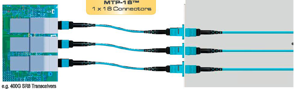
Figure 12 400G SR8 Cabling Scenario for New Data Center (Source: US CONEC)
For data centers that have already deployed MPO-MTP-12 or MPO/MTP-24 cabling, a smooth upgrade to 400G SR8 can be achieved by replacing with 4×3 MPO/MTP conversion boxes. By using 4×3 MPO/MTP conversion boxes, the existing 12-core or 24-core cabling can be converted to the required 16-core MPO/MTP cabling compatible with the 400G SR8 optical modules.
This upgrade approach maximizes the utilization of the existing cabling infrastructure, avoiding the need for a comprehensive overhaul of the fiber cabling system, thus reducing the costs and effort involved in the upgrade. Through this seamless upgrade approach, data centers can conveniently accommodate the application of 400G SR8 optical modules, meeting the demands of high bandwidth and high-speed transmission.
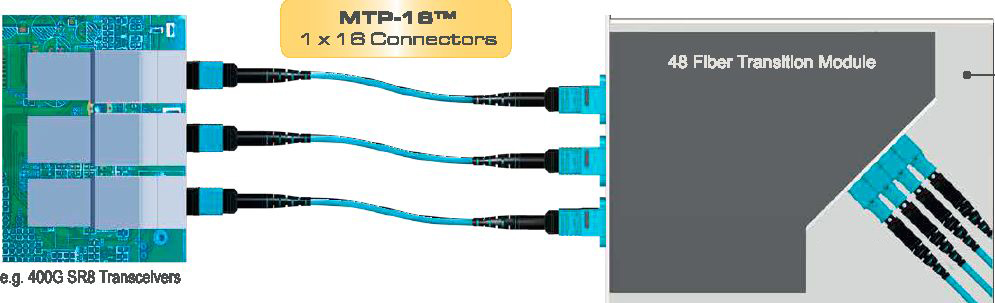
Figure 13 400G SR8 Cabling Scenario for Existing Data Center (Source: US CONEC)
The 400G SR8 optical module offers a broader range of breakout options, including 4x100G, 8x50G, and 2x200G. On the other hand, the 400G SR4.2 and 400G DR4 optical modules only support 4x100G breakout. Therefore, when selecting optical modules, it’s essential to determine the most suitable solution based on the specific requirements of the data center. This ensures stable high-speed data transmission and connectivity.
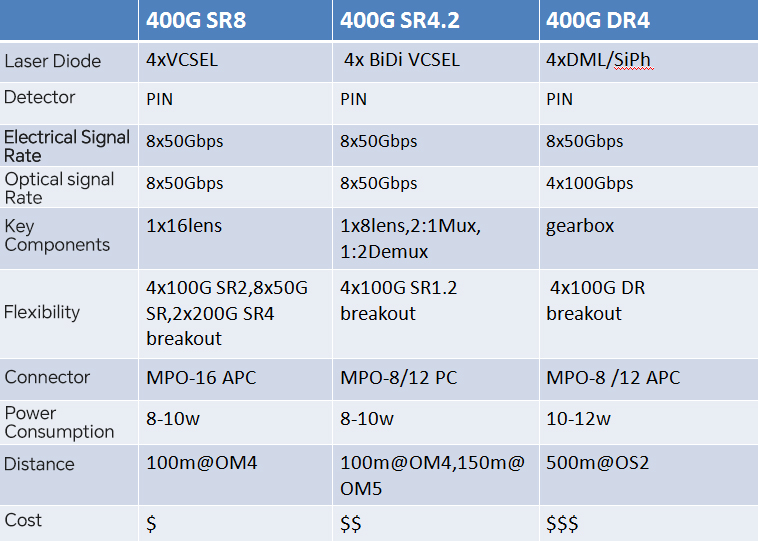
Figure 14 Comparison of 400G optical modules for switch interconnection 100m-500m
The cost of a data center network comprises both optical modules and cabling. While the 400G SR8 optical module requires a higher number of optical fiber cores, data centers usually employ modular designs, and the interconnect distances for switches are generally around 50 meters. As a result, the differences in cabling costs are relatively small compared to the cost of optical modules. Additionally, the 400G SR8 optical module boasts a well-established ecosystem with numerous suppliers, supporting various breakout applications. Therefore, for newly deployed data centers, within a range of 115 meters, the 400G SR8 offers the lowest overall cost and the highest cost-effectiveness for 400G switch interconnect solutions.
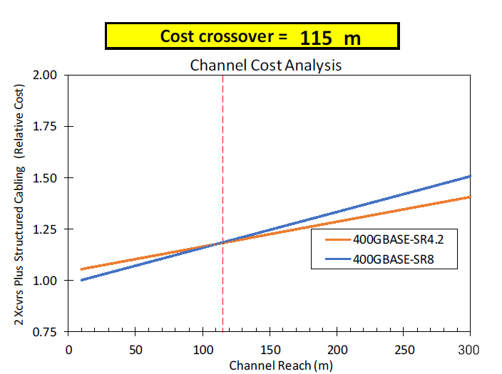
Figure 15 Overall cost comparison for data center switch interconnection (Source: Panduit)
Data Center Interconnection(DCI)
Comparison of Data Center Interconnection Optical Modules for 2-10km
For data center interconnection within the range of 2km to 10km, there are four available options.
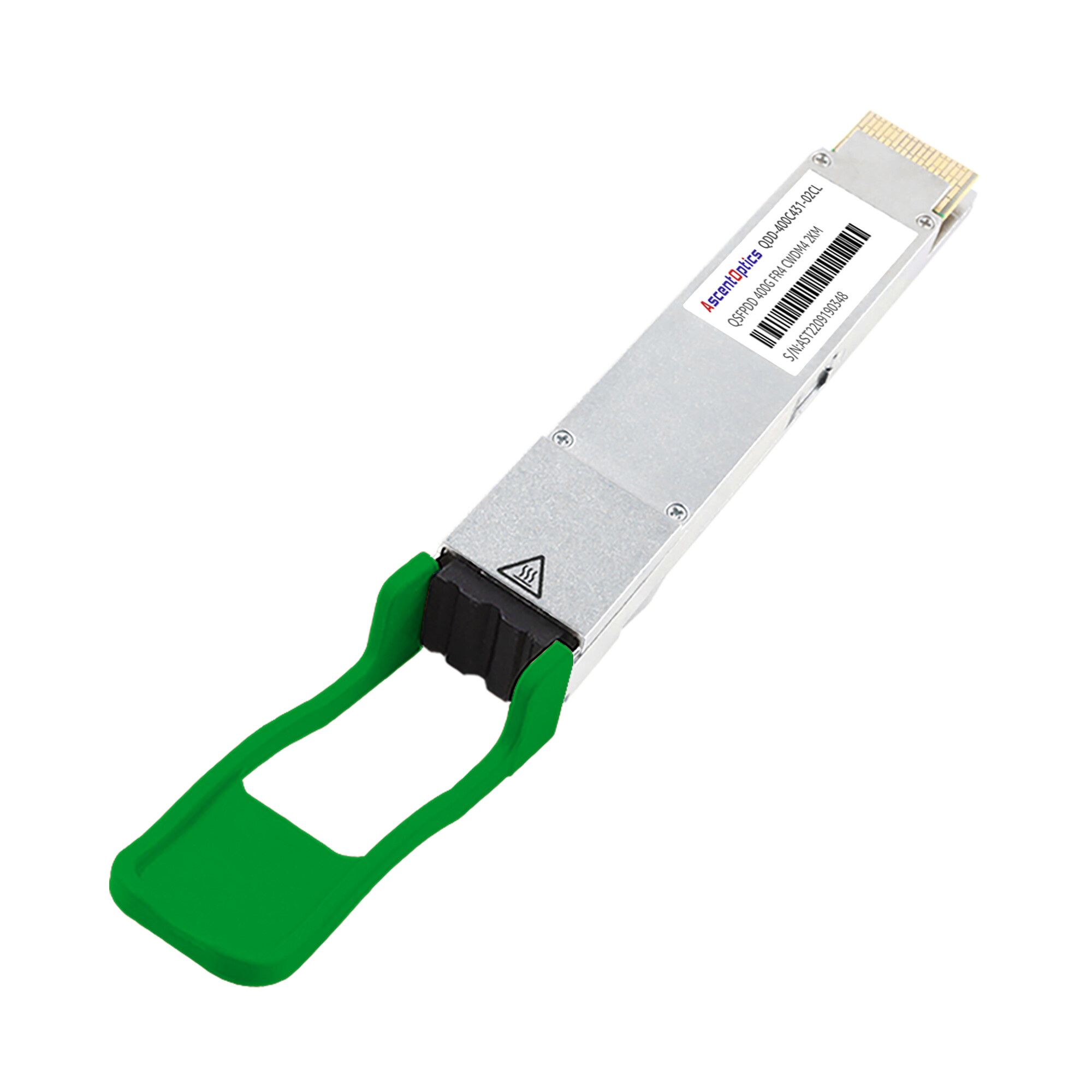
The 400G FR8 solution requires 8 DML lasers. In order to reduce the number of lasers and complexity, the 400G FR4 optical module only requires 4 EML lasers, thus decreasing component and assembly costs.The 400G FR8 solution adopts LAN-WDM wavelength division multiplexing technology, supporting 8 wavelengths with a transmission rate of 50Gbps per wavelength.On the other hand, the 400G FR4 solution utilizes CWDM technology, supporting 4 wavelengths with a transmission rate of 100Gbps per wavelength.
Currently in the market, achieving a single-wavelength 100Gbps transmission requires the use of expensive 50G baud-rate optical and electrical chips. To achieve 100G DR transmission, there are three options available.
Option 1 employs a 4:1 gearbox, converting the 4x25Gbps electrical signals from the switch to a single 1x100Gbps electrical signal for the optical module, with a power consumption of 3.5W. The option 2 uses a 2:1 gearbox, converting the 4x25Gbps electrical signals to a single 1x100Gbps electrical signal for the optical module, with a power consumption of 2.5W. And option 3 utilizes a single-wavelength 100Gbps solution, eliminating the need for costly gearboxes and reducing power consumption to 1.5W.
Based on specific requirements and budget considerations, we can choose suitable optical modules and transmission schemes to meet the high-speed transmission needs of data center interconnections.

Figure 16 Power consumption comparison of different 100G DR schemes (Source: Arista)
The adoption of a single-wavelength 100Gbps solution eliminates the need for costly gearboxes, resulting in reduced device costs and power consumption. With ongoing improvements and widespread adoption of 50Gbaud-rate chips, the 400G FR4 is expected to gradually replace the 400G FR8. While 400G FR8 is currently mature and widely used, technological advancements and market competition are driving 400G FR4 to become a more appealing high-speed data transmission solution. This transition will cater to the growing demands while aligning with energy-efficient and environmentally-friendly trends.
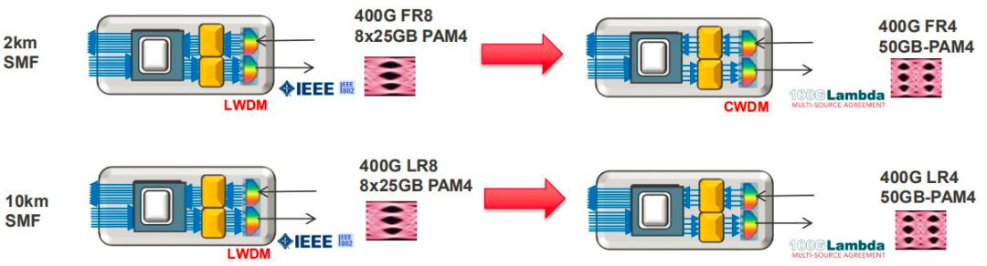
Figure 17 Road map for Data center interconnect network evolution (Source: Molex)
The 400G FR4 utilizes a larger 20nm wavelength spacing, which relaxes the requirements for the multiplexer (Mux) and demultiplexer (Demux) components, and the lasers do not require cooling. This reduction in cooling requirements leads to lower costs for the optical module. In contrast, the 400G LR4 uses a narrower 5nm wavelength spacing, which requires the integration of costly temperature control equipment (TEC) for cooling purposes. This inclusion of TEC leads to higher costs for the 400G LR4 optical module. Therefore, within a transmission distance of 2 kilometers, the 400G FR4 is considered a more cost-effective solution.
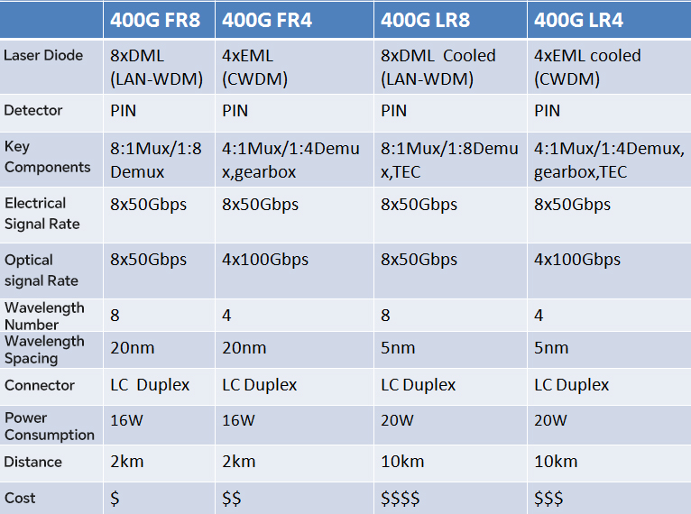
Figure 18 Comparison of data center interconnect optical modules for 2-10km
Comparison of Data Center Interconnect Optical Modules for 40km
For data center interconnect within a 40km distance, the options include the 400G ER8 and 400G ER4 solutions. However, the 400G ER8 comes with higher costs due to the utilization of expensive EML lasers and APD detectors, along with the requirement for Mux and Demux components. Additionally, the higher power consumption of EML lasers necessitates the inclusion of a temperature control device (TEC) to ensure stable modulation signals. These factors collectively contribute to the higher cost of both the 400G ER8 and 400G ER4 optical modules.
The 400G ER4 solution employs single-wavelength 100Gbps transmission, using expensive 50Gbps baud rate EML laser chips. In contrast, the 400G ER8 solution utilizes the currently market-established 25Gbps baud rate EML laser chips. Additionally, the 400G ER4 optical module requires the conversion of 8x50Gbps electrical signals from the switch side to 4x100Gbps electrical signals, necessitating the inclusion of a gearbox. This extra component significantly raises the cost of the 400G ER4 solution compared to the 400G ER8, making it a more expensive option.
Therefore, for data center interconnect within a 40km distance, the 400G ER8 proves to be the more economical choice. Both the 400G ER4 and 400G ER8 have their own advantages. However, selecting the appropriate optical module solution based on specific requirements and budget is crucial.
Comparison of Data Center Interconnect Optical Modules for 80km
As network speeds increase, traditional methods like simple on-off keying amplitude modulation with direct detection pose challenges in data center interconnect scenarios, leading to reduced transmission distances and issues with interference. Coherent detection communication is a complex multidimensional signal modulation technique. It combines amplitude, phase, and polarization modulation, enabling the transmission of more information within a single baud rate.
The Optical Internetworking Forum(OIF) is currently developing the 400G ZR specification, which combines coherent detection and dense wavelength division multiplexing (DWDM). This approach employs sophisticated 16-level quadrature amplitude modulation and polarization multiplexing techniques to support transmission distances of up to 80km.
The 400G ZR optical module requires costly integrated tunable lasers, IQ phase modulators, high-performance digital signal processors for signal compensation, and coherent receivers for detecting intricate modulation signals. As a result, the price of a 400G ZR optical module is approximately twice that of a 400G ER4 module. Despite its higher cost, the 400G ZR technology offers greater transmission distances and higher signal capacity. This makes it a compelling solution for data center interconnection scenarios requiring long-distance, high-capacity transmission.

Figure 19 Comparison of data center interconnect optical modules for 80km
Conclusion
Conclusion of data center 400G optical module options:
1. Interconnect scenario between ToR switch and server within 2.5m: Utilize 400G DAC (Direct Attach Cable).
2. Interconnect scenario between ToR switch and server with 30m: Opt for 400G AOC (Active Optical Cable).
3. Interconnect scenario between Spine-Leaf switches within 100m: Employ 400GBASE-SR8 QSFP-DD optical module, utilizing MPO/MTP-16 OM4 Multi-mode fiber for cabling.
4. Interconnect scenario between Spine-Leaf switches within 150m: Opt for 400GBASE-SR4.2 QSFP-DD optical module, with cabling utilizing MPO/MTp-12 OM5 multi-mode fiber.
5. Interconnect scenario between Spine-Leaf switches within 500m: Select 400G DR4 QSFP-DD optical module, with cabling using MPO/MTP-12 OS1a single-mode fiber.
6. Interconnect scenario within 2km for data centers: Employ 400G FR8 QSFP-DD optical module, with cabling utilizing OS2 single-mode fiber.
7. Interconnect scenario within 10km for data centers: Opt for 400G-LR8 OSFP optical module, with cabling using OS2 single-mode fiber.
8. Interconnect scenario within 40km for data centers: Choose 400G-ER8 OSFP optical module, with cabling using OS2 single-mode fiber.
9. Interconnect scenario within 120km for data centers: Utilize 400G-ZR coherent CSFP2 optical module, with cabling utilizing OS2 single-mode fiber.
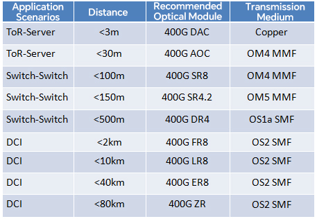
Figure 20 Data Center Application Scenarios and Optical Module Selection
We can choose suitable 400G optical module solutions based on the requirements and distance of data centers to ensure efficient and stable data transmission.
Post Views: 8,466