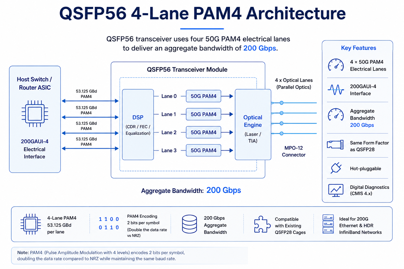
The QSFP56 transceiver is a high-speed, hot-pluggable optical module that uses four 50 Gbps PAM4 electrical lanes to deliver an aggregate bandwidth of 200 Gbps. It is widely deployed in 200G Ethernet and HDR InfiniBand networks, providing high-density, energy-efficient connectivity for modern data centers.
Featuring four electrical lanes operating at 50G PAM4, QSFP56 delivers an aggregate bandwidth of 200G while maintaining the same compact footprint as QSFP28. It serves as an important transition technology between 100G QSFP28 and higher-density 400G QSFP-DD deployments.
The module is hot-swappable, compatible with mainstream network equipment, and equipped with digital diagnostic functions for real-time link status monitoring. With its excellent signal integrity and energy efficiency, the QSFP56 has become an ideal choice for short-reach optical interconnects in next-generation cloud computing and high-performance computing clusters, effectively meeting the ever-growing bandwidth demands of hyperscale data centers.
What Is a QSFP56 Transceiver?
A QSFP56 transceiver is a hot-pluggable optical module that supports 200 Gigabit Ethernet using four 50 Gbps PAM4 electrical lanes. It shares the same mechanical form factor as QSFP28 but requires host hardware capable of 200G PAM4 signaling.
QSFP56 stands for Quad Small Form-Factor Pluggable 56. Although “56” is part of the product name inherited from the MSA, QSFP56 modules actually use four 53.125 GBd PAM4 electrical lanes to deliver an effective payload rate of 50 Gbps per lane. Four lanes combined deliver an aggregate 200 Gbps, making QSFP56 the natural bridge between 100G QSFP28 and 400G QSFP-DD networks.
Key specifications of a typical QSFP56 transceiver module include:
- •Form factor: QSFP56 MSA, same mechanical size as QSFP28
- •Electrical interface: 200GAUI-4 (4 x 53.125 Gbps PAM4)
- •Aggregate data rate: 200 Gbps
- •Power supply: Single +3.3V
- •Power consumption: 3 W to 7 W depending on the reach class
- •Digital diagnostics: DDM/DOM via I2C with CMIS 4.0 management
- •Operating temperature: 0 °C to 70C commercial grade, typical
- •Standards: IEEE 802.3bs, IEEE 802.3cd, QSFP56 MSA, SFF-8665, SFF-8679
Because QSFP56 uses PAM4 modulation instead of NRZ, it can double the data rate without adding lanes or enlarging the module. That is why network teams can often reuse existing QSFP28 cages and cabling infrastructure when upgrading to 200G, provided the switch ASIC supports 200G PAM4 signaling.
How QSFP56 Works: PAM4 vs NRZ
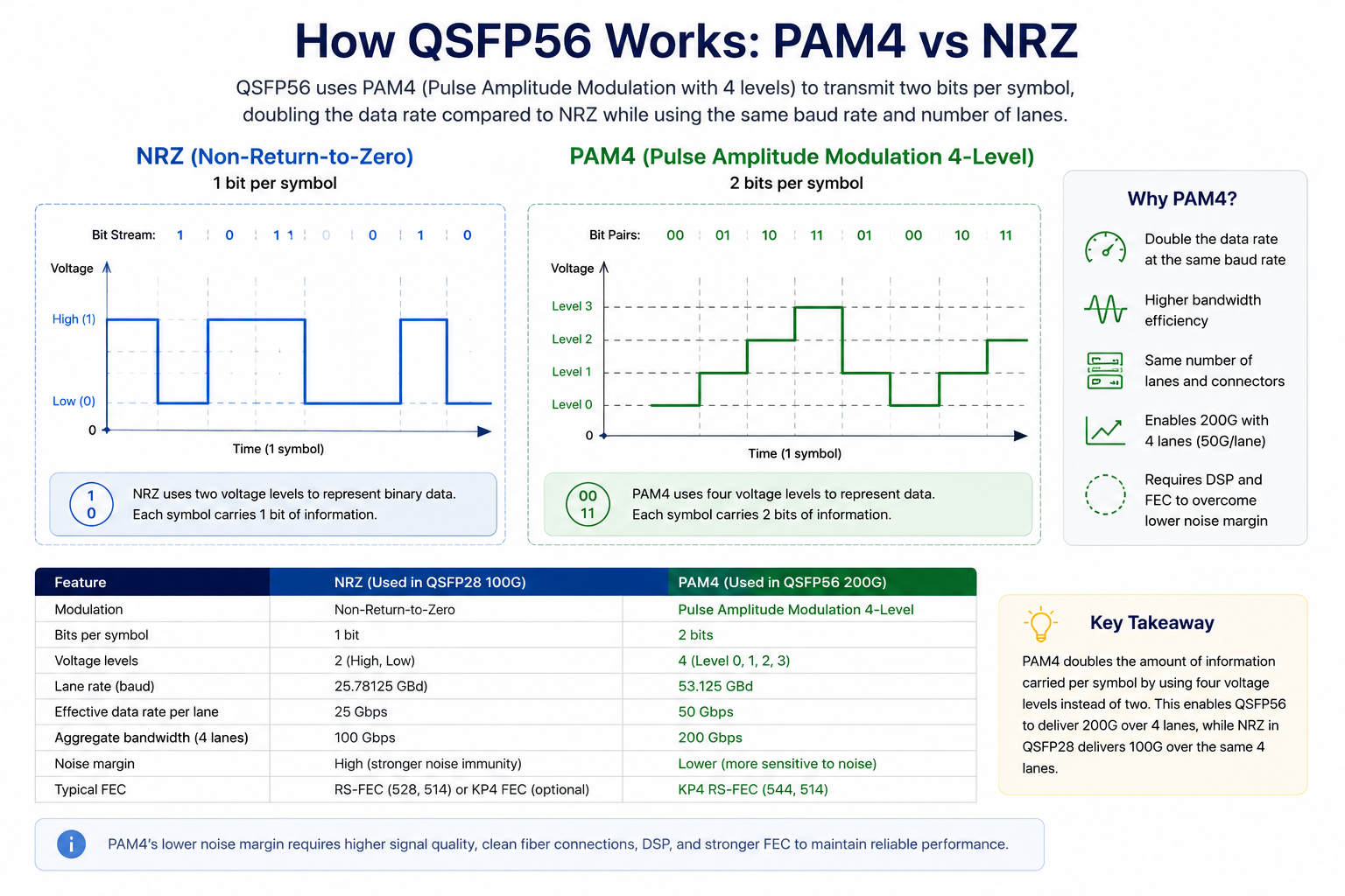
Understanding QSFP56 starts with understanding modulation. Older 100G QSFP28 modules use NRZ, or Non-Return-to-Zero, signaling. NRZ transmits one bit per symbol: a high voltage level represents a 1, and a low voltage level represents a 0. It is simple, has strong noise immunity, and works reliably across long distances.
QSFP56 uses PAM4, or Pulse Amplitude Modulation 4-level. PAM4 encodes two bits per symbol across four voltage levels: 00, 01, 10, and 11. By packing twice as much information into each symbol, PAM4 doubles the bit rate at the same baud rate. This is how QSFP56 achieves 200 Gbps across only four lanes instead of the eight lanes a traditional NRZ approach would require.
The trade-off is the noise margin. Because PAM4 distinguishes four signal levels instead of two, each level is closer together, making the signal more sensitive to noise, crosstalk, and insertion loss. To compensate, QSFP56 modules rely on digital signal processors, or DSPs, and stronger forward error correction, typically KP4 RS-FEC (544,514).
The practical impact for network engineers is threefold:
- 1. Higher power consumption: DSPs and FEC add wattage. A QSFP56 module typically consumes 4 W to 7 W, compared with 3 W to 3.5 W for QSFP28.
- 2. Shorter reach at the same fiber quality: PAM4 links have lower signal-to-noise margins and tighter insertion-loss budgets than NRZ, making channel quality more critical even when the supported transmission distance remains the same.
- 3. Stricter cabling cleanliness: MPO connector contamination that might be tolerable at 25 Gbps NRZ can cause bit errors at 50 Gbps PAM4. Proper cleaning and polarity management become essential.
Despite these trade-offs, PAM4 has become the industry standard for 200G, 400G, and 800G Ethernet because it preserves port density and form-factor compatibility across generations.
QSFP56 Module Types and Specifications
QSFP56 transceivers are classified by IEEE 802.3bs and 802.3cd standards according to reach, fiber type, and optical interface. Choosing the right variant means matching distance requirements, fiber plant, and connector strategy.
| Module Type |
Fiber Type |
Wavelength |
Max Distance |
Connector |
Typical Power |
Common Use Case |
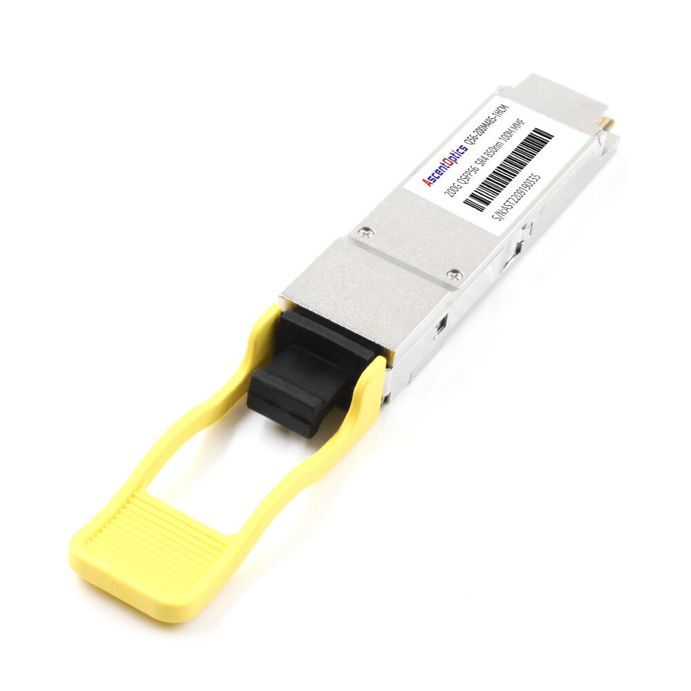
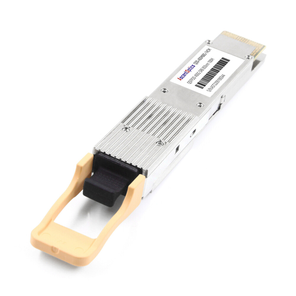
| 200GBASE-SR4 |
MMF OM3/OM4/OM5 |
850 nm |
70 m OM3 / 100 m OM4 |
MPO-12 |
3.3 W – 4.5 W |
Top-of-rack, intra-data-center |
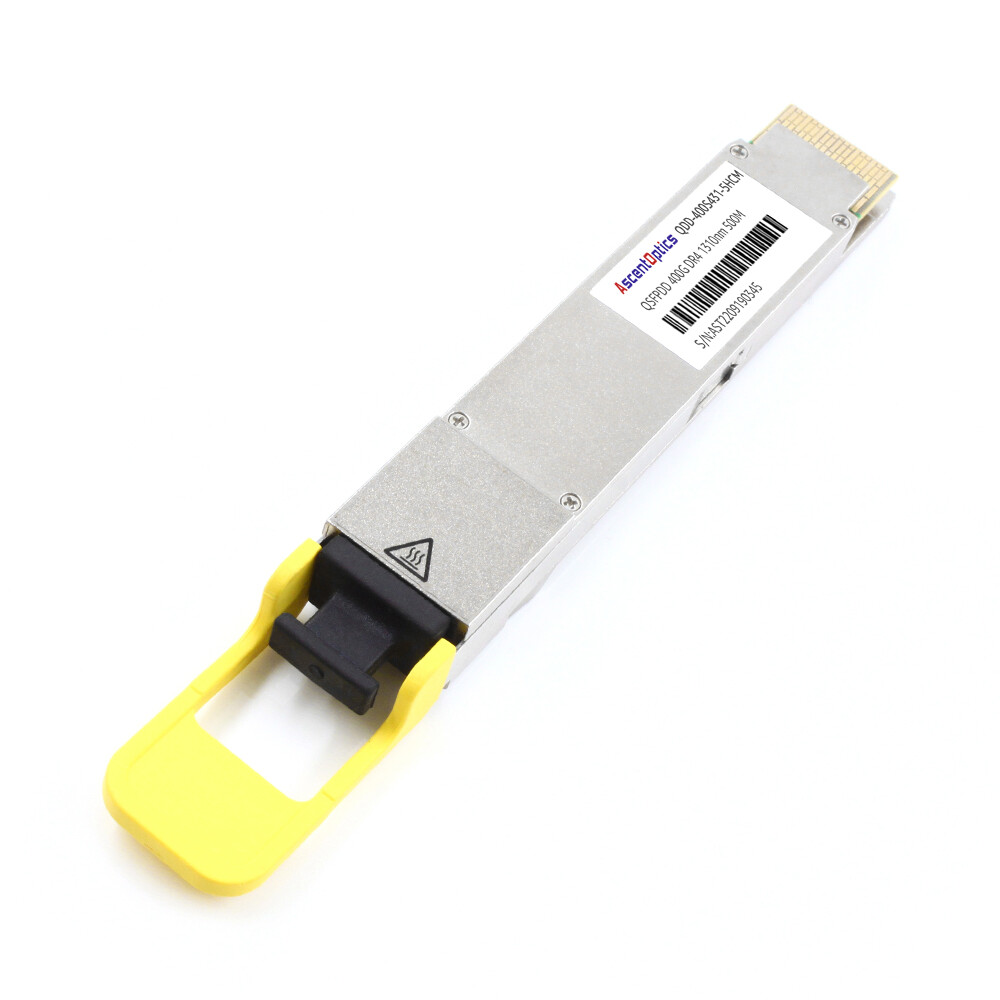
| 200GBASE-DR4 |
SMF |
1310 nm |
500 m |
MPO-12 |
4.5 W – 6 W |
Data center interconnects |
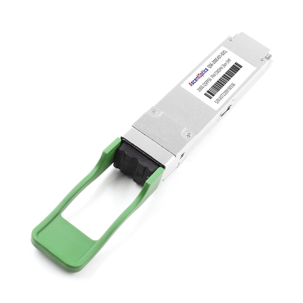
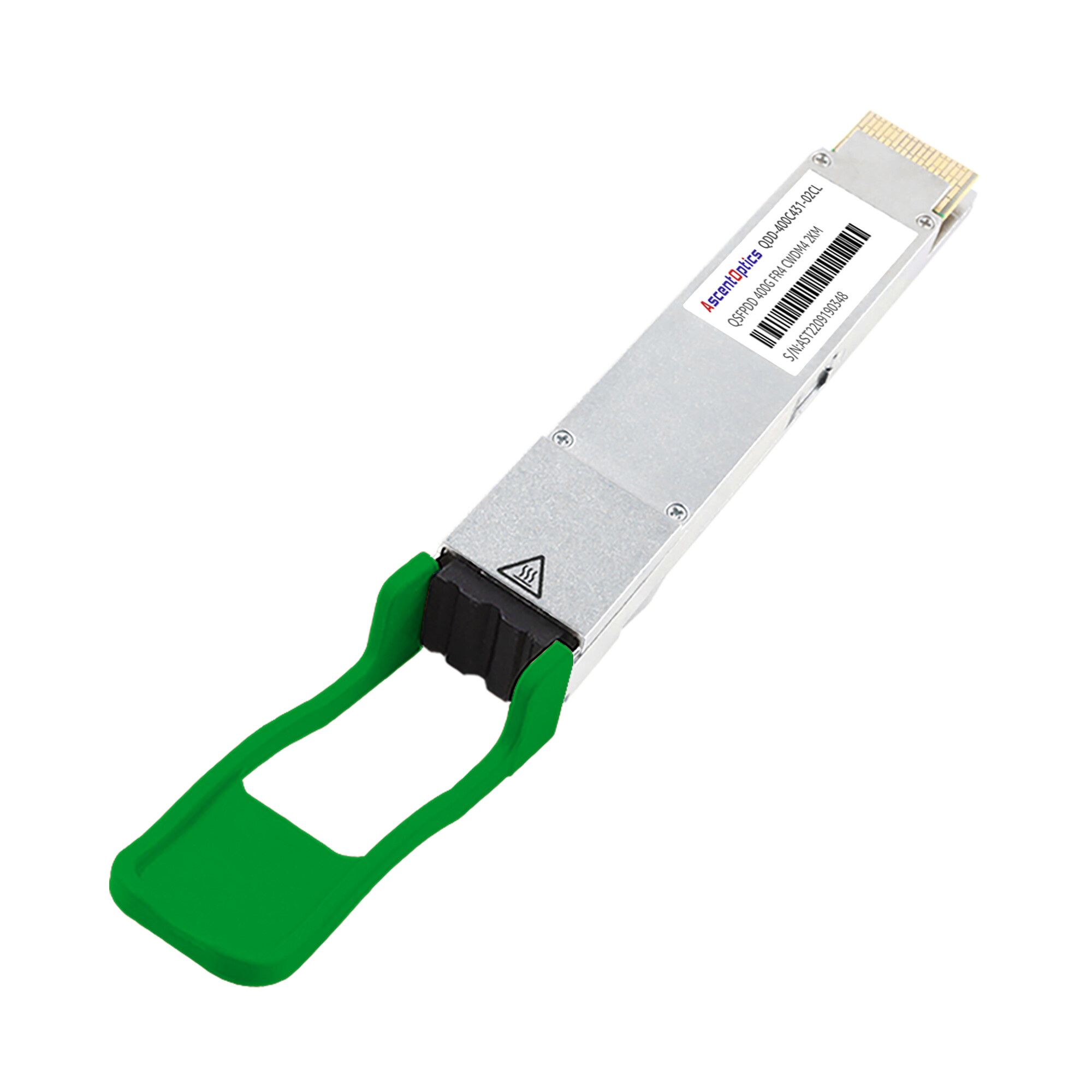
| 200GBASE-FR4 |
SMF |
1271-1331 nm CWDM4 |
2 km |
LC duplex |
5 W – 6.5 W |
Campus, metro aggregation |
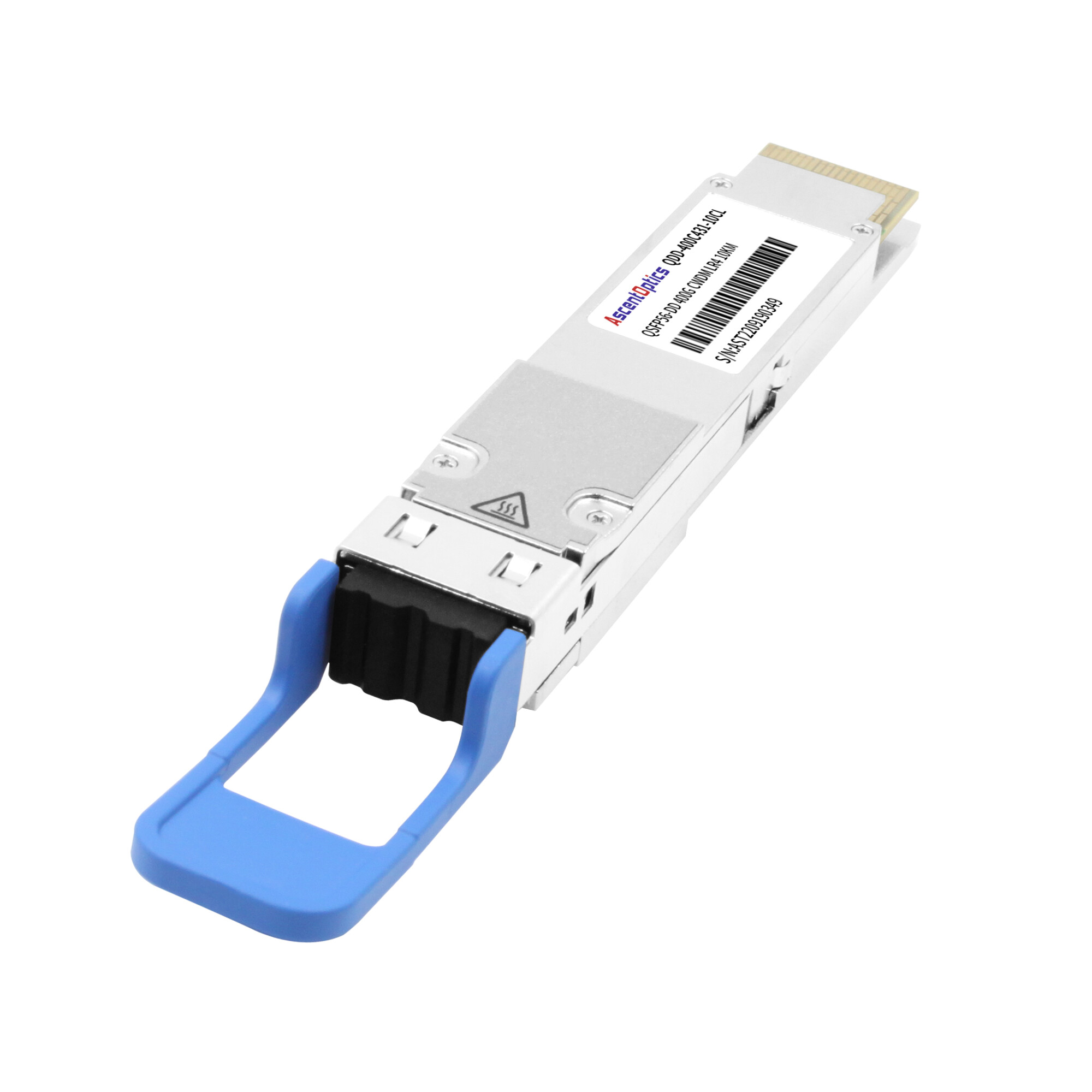
| 200GBASE-LR4 |
SMF |
1295-1309 nm LAN-WDM |
10 km |
LC duplex |
5.5 W – 7 W |
Telecom, long-distance links |
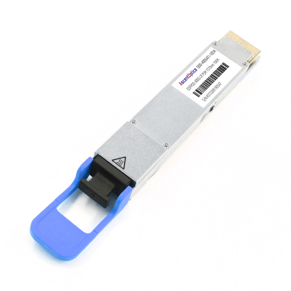
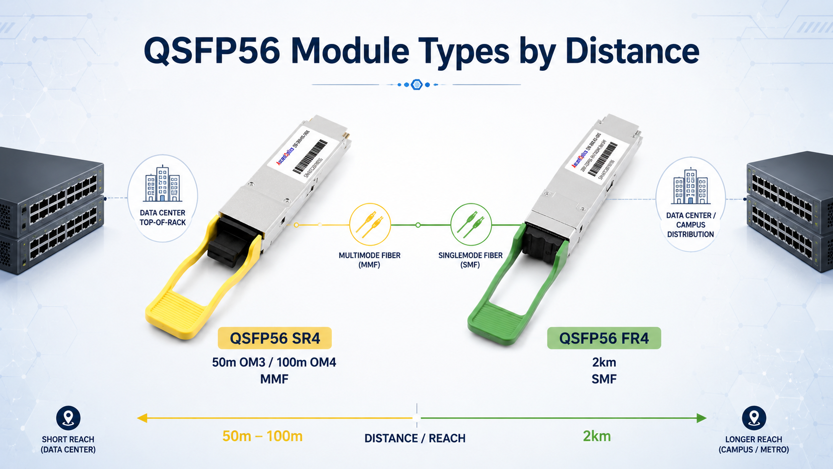
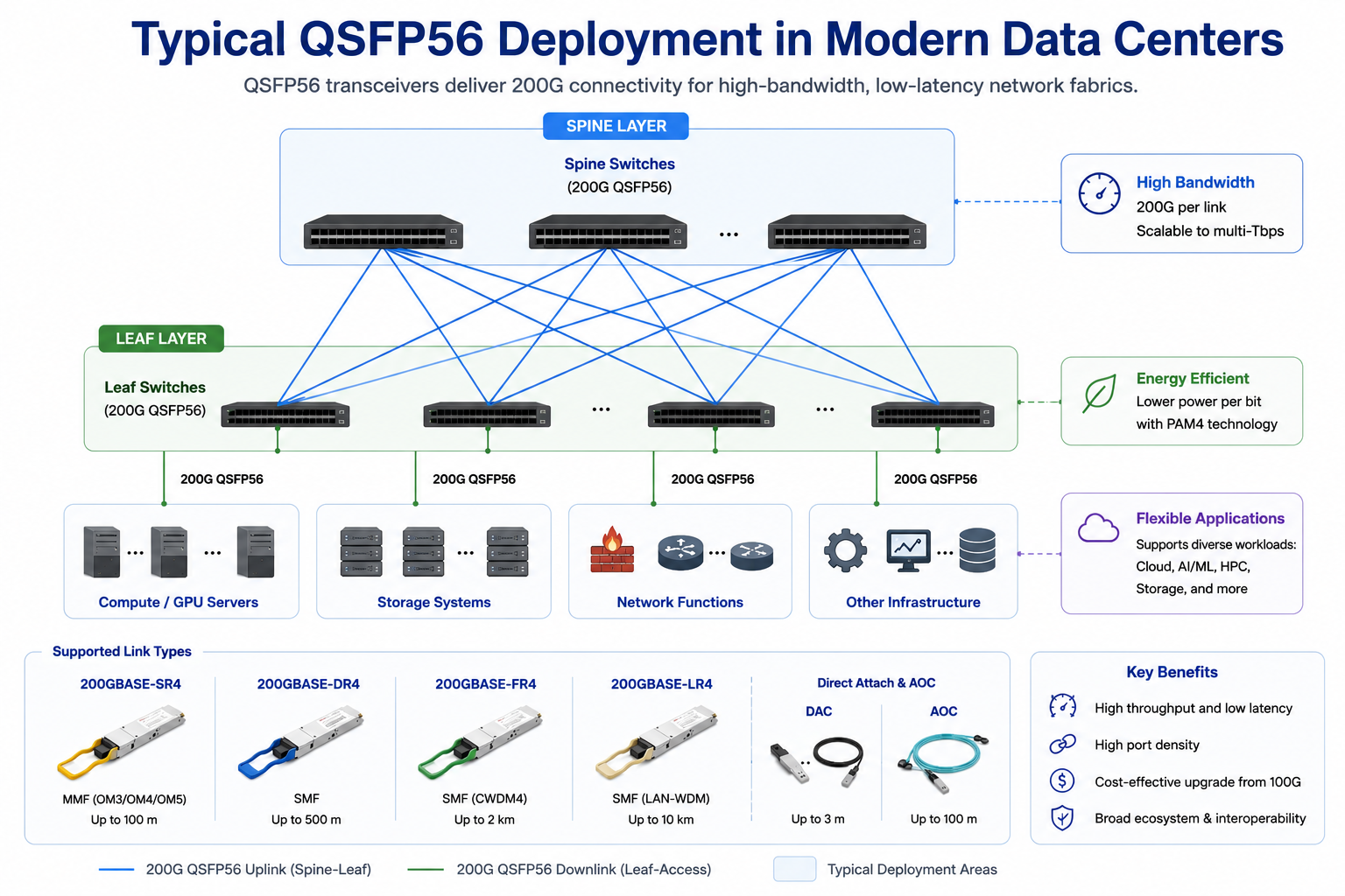
SR4 is the short-reach multimode workhorse. It uses four VCSEL lasers at 850 nm and an MPO-12 connector. For data centers with existing OM4 MPO cabling, SR4 is usually the lowest-cost path to 200G. A 200G QSFP56 SR4 module can support up to 100 meters on OM4 fiber, with slightly longer reach possible on OM5.
200GBASE-DR4
DR4 extends reach to 500 meters on single-mode fiber using four parallel 1310 nm lanes and an MPO-12 connector. It is commonly used for data center interconnects between buildings or across large colocation facilities. The move to single-mode fiber adds cost but removes the distance limitations of multimode optics.
FR4 uses four CWDM wavelengths multiplexed onto a single fiber pair, enabling a duplex LC connector and a 2 km reach. It is popular for campus networks and metro aggregation where distance exceeds DR4 limits, but the LR4 cost is not justified.
200GBASE-LR4
LR4 supports 10 km over single-mode fiber using LAN-WDM wavelengths. Telecom operators and enterprises with geographically distributed sites often choose LR4 for backbone and aggregation links.
DAC and AOC Options
In addition to optical transceivers, QSFP56 supports passive direct attach copper, or DAC, cables and active optical cables, or AOCs. DACs are cost-effective for very short links, typically under 3 meters, but consume no optical power and add minimal latency. AOCs support longer distances, up to 100 meters, and are lighter and more flexible than DACs for dense racks.
Network architects often face a three-way decision: stay with 100G QSFP28, deploy 200G QSFP56, or jump directly to 400G QSFP-DD. Each choice has different implications for bandwidth, power, cost, and migration path.
| Feature |
QSFP28 |
QSFP56 |
QSFP-DD |
| Data rate |
100 Gbps |
200 Gbps |
400 Gbps / 200 Gbps |
| Lanes |
4 x 25 Gbps |
4 x 50 Gbps |
8 x 50 Gbps |
| Modulation |
NRZ |
PAM4 |
PAM4 for 400G |
| Form factor |
Standard QSFP |
Standard QSFP |
Double-density QSFP |
| Mechanical size |
18.35 x 72.3 x 8.5 mm |
Same as QSFP28 |
18.35 x 89.4 x 8.5 mm |
| Power consumption |
3 W – 3.5 W |
4 W – 7 W |
7 W – 13 W |
| Backward compatibility |
QSFP+ cages |
QSFP+/QSFP28 cages (mechanical) |
QSFP+/QSFP28/QSFP56 cages |
| Typical use case |
Mature 100G links |
200G upgrade step |
Future-proof 400G |
QSFP56 is not backward compatible with QSFP28 at the signal level. A QSFP56 module requires a QSFP56-capable port. However, the mechanical form factor is identical, so QSFP56 modules physically fit into QSFP28 cages. Some switches support configuring a QSFP56 port to operate at 100G with a QSFP28 module, but the reverse is not true: a QSFP28 port cannot run a QSFP56 module at 200G.
QSFP-DD, by contrast, doubles the number of electrical lanes to eight while maintaining backward compatibility with older QSFP modules. It is the preferred choice when future-proofing for 400G is the priority. However, QSFP-DD switches and modules still carry a price premium, and not every network needs 400G density today.
QSFP56 Compatibility and Standards
Interoperability is where 200G deployments often succeed or fail. QSFP56 modules must comply with the QSFP56 MSA, IEEE 802.3bs, IEEE 802.3cd, IEEE 802.3cm, and SFF-8665 / SFF-8679 specifications. These standards define the mechanical, electrical, and optical interfaces that allow modules from different vendors to work in the same switch port. QSFP56 ports are generally backward compatible with QSFP28 modules at the mechanical level, provided the host platform supports 100G operation.
In practice, however, several factors affect compatibility:
- •Switch ASIC support: The switch must have ports capable of 200GAUI-4 signaling. Not all 100G switches support this.
- •Firmware version: Some platforms require a minimum firmware release to enable 200G mode or to recognize third-party QSFP56 modules.
- •FEC matching: Both ends of a 200G link must use the same FEC mode. RS-FEC (544,514) is typical for 200GBASE-SR4 and 200GBASE-DR4, while some FR4/LR4 implementations may use a different FEC configuration.
- •Vendor coding: Major OEM switches may check vendor identifiers in the module EEPROM. Third-party modules coded for the target platform usually resolve this, but uncoded generic modules may be rejected.
- •CMIS version: QSFP56 modules use CMIS 4.0 for management. Ensure your switch supports the correct CMIS revision to read DOM thresholds and alarms reliably.
Vendor Compatibility Notes
|
Vendor Platform
|
QSFP56 Support Notes
|
| Cisco |
Available on Nexus 9000 and Catalyst 9000 families; verify port speed and FEC settings per line card |
| Arista |
Broadly supported on 7060X, 7260, and 7320 series; check firmware for 200G breakout modes |
| Juniper |
Supported on QFX5000 and PTX series; confirm optics compatibility matrix |
| NVIDIA/Mellanox |
Native for InfiniBand HDR and 200GbE Spectrum switches; commonly uses QSFP56 SR4 and DR4 |
| Dell |
Supported on select Z-Series switches; verify port configuration and FEC requirements |
QSFP56 Applications: Data Centers, AI/ML, and Telecom
The 200G data rate sits at a practical inflection point. It doubles spine-layer bandwidth without requiring a full 400G investment, and it supports several high-growth use cases.
Hyperscale Data Center Spine-Leaf Upgrades
In leaf-spine architectures, 200G QSFP56 modules are commonly used for spine-to-leaf uplinks. A spine switch with 32 x 200G ports can deliver 6.4 Tbps of fabric capacity, sufficient for many mid-scale data centers before moving to 400G spine layers.
AI/ML Clusters and InfiniBand HDR
AI training clusters demand low-latency, high-bandwidth interconnects between GPU servers and leaf switches. 200G QSFP56 modules are widely used in InfiniBand HDR fabrics and 200GbE RDMA networks. In rail-optimized GPU clusters, 200G links connect compute nodes to top-of-rack switches with minimal cabling complexity.
NVIDIA Quantum HDR and Spectrum-2/3 Ethernet switches remain common QSFP56 deployment platforms, although newer AI clusters are increasingly transitioning to NDR (400G) and XDR (800G) interconnects.
HPC and RDMA Fabrics
High-performance computing environments use 200G QSFP56 modules for RoCEv2 and InfiniBand links. The low latency and high throughput support tightly coupled workloads where every microsecond matters.
Enterprise and Telecom Aggregation
Service providers and large enterprises deploy 200GBASE-FR4 and LR4 modules for campus interconnects, mobile backhaul aggregation, and metro Ethernet. The 2 km and 10 km reach classes cover most intra-city requirements without the cost of coherent optics.
How to Choose the Right QSFP56 Transceiver
Selecting a QSFP56 transceiver module comes down to four practical steps.
Step 1: Determine Required Reach and Fiber Type
Measure the physical link distance and identify the installed fiber. Multimode fiber supports SR4 for short links. Single-mode fiber is required for DR4, FR4, LR4, and ER4. If you are reusing existing cabling, confirm the fiber type, connector type, and polarity before ordering modules.
Step 2: Confirm Host Platform and FEC Support
Verify that your switch or router supports QSFP56 ports at 200G. Check the firmware version, FEC requirements, and whether the platform requires vendor-coded optics. Plan a sample qualification if you are using third-party modules.
Step 3: Select Connector and Cabling Strategy
Parallel optics such as SR4 and DR4 use MPO-12 connectors. WDM optics such as FR4 and LR4 use LC duplex. Make sure your patch panels, trunk cables, and polarity scheme match the module connector. If you need a breakout, confirm whether the switch supports 200G to 2 x 100G or 200G to 4 x 50G split modes.
Step 4: Evaluate Power, Thermal, and Warranty
Add up the per-module power consumption for all ports in a switch. At 5 W to 7 W per module, a 32-port switch can generate 160 W to 220 W of optical heat alone. Ensure your rack airflow and cooling can handle the load. Finally, evaluate the supplier’s warranty, testing documentation, and technical support capability.
Installation, Troubleshooting, and Best Practices
Even a correctly specified QSFP56 link can fail if installation details are overlooked. The following practices help avoid common problems.
Port Enablement and Configuration
- 1. Insert the module and verify that the switch recognizes it via the CLI or management interface.
- 2. Set the port speed to 200G if it does not auto-negotiate.
- 3. Configure FEC mode consistently on both ends of the link.
- 4. Check DOM/DDM thresholds for voltage, temperature, transmit power, and receive power.
- 5. Monitor pre-FEC BER, post-FEC BER, laser bias current, and module temperature through CMIS diagnostics to identify early degradation before link failures occur.
Common Link Failures and Diagnostics
- •Link does not come up: Check firmware version, port speed setting, and module vendor coding.
- •High bit error rate: Clean MPO or LC connectors, verify polarity, and inspect for bent pins or damaged ferrules.
- •FEC mismatch errors: Ensure both ends use the same RS-FEC configuration.
- •Thermal alarms: Verify airflow direction, ambient temperature, and whether adjacent ports are overloading the switch thermal budget.
- •Link flapping: Reseat the module, check cable bend radius, and confirm the cable is rated for 200G signaling.
MPO Polarity and Fiber Cleaning
MPO polarity methods A, B, and C determine how transmit and receive fibers align between modules. Using the wrong polarity method causes a link failure even when all hardware is functional. Always clean MPO and LC connectors with approved tools before installation, and use dust caps when cables are not connected.
Thermal and Rack-Level Power Planning
A fully populated 32-port 200G switch can draw 160 W to 220 W just from optical modules. Combined with switch ASIC power, this creates significant heat density. Plan front-to-rear airflow, blanking panels for unused ports, and adequate rack cooling before deploying dense 200G fabrics.
Conclusion
The QSFP56 transceiver gives network engineers a clear upgrade path from 100G to 200G without forcing a premature jump to 400G. By using four 50 Gbps PAM4 lanes, QSFP56 doubles bandwidth in the same QSFP form factor that data centers already know. The key to a successful deployment is matching the right module type, SR4, DR4, FR4, LR4, or ER4, to your distance, fiber, and connector requirements, and then confirming switch compatibility, FEC settings, and firmware support before scaling.
Although many hyperscale operators are adopting 400G and 800G networking, QSFP56 continues to offer an excellent balance of bandwidth, cost, and infrastructure reuse for enterprise, HPC, and mid-scale cloud environments. By understanding PAM4 signaling, module types, compatibility requirements, and deployment best practices, network architects can confidently build scalable 200G Ethernet and InfiniBand networks while preparing for future upgrades.
FAQ
-
1. What is a QSFP56 transceiver used for?
A QSFP56 transceiver is primarily used to deliver 200G network connectivity in modern data centers, cloud computing environments, high-performance computing (HPC) clusters, and AI infrastructure. It supports 200 Gigabit Ethernet and HDR InfiniBand networks, providing high bandwidth, low latency, and high port density for switch-to-switch and switch-to-server interconnects.
-
2. What is the difference between QSFP56 and QSFP28?
The main difference is the signaling technology and bandwidth. QSFP28 uses four 25 Gbps NRZ lanes to deliver 100 Gbps, while QSFP56 uses four 50 Gbps PAM4 lanes to achieve 200 Gbps. Although both share the same physical form factor, a QSFP56 module requires a host platform that supports 200G PAM4 signaling.
-
3. Is QSFP56 compatible with QSFP28 ports?
Physically, QSFP56 modules have the same dimensions as QSFP28 modules. However, a QSFP56 transceiver cannot operate at 200G in a QSFP28 port because the host does not support PAM4 signaling. Many QSFP56 switches, on the other hand, can accept QSFP28 modules and operate them at 100G, depending on the switch hardware and software.
-
4. Does QSFP56 support breakout connectivity?
Yes. Many QSFP56 switches support breakout configurations, such as 1×200G to 2×100G, allowing a single 200G port to connect to two independent 100G interfaces. Breakout support depends on the switch ASIC, operating system, and firmware, so compatibility should be verified before deployment.
-
5. How much power does a QSFP56 transceiver consume?
Power consumption typically ranges from 3 W to 7 W, depending on the module type and transmission distance. Short-reach SR4 modules generally consume less power, while long-reach FR4 and LR4 modules require additional optical components and DSP processing, resulting in higher power consumption.
Post Views: 24