Marcus Chen stared at the packing list for his new NVIDIA Quantum-2 switch delivery and felt a familiar knot form in his stomach. The spine switches supported 800G OSFP ports, but his data center still housed over six hundred servers with 400G ConnectX-7 NICs. A full endpoint replacement would cost $3.2 million and require four months of coordinated downtime across three facilities. His CFO had already rejected the capital request once.
Then Marcus discovered OSFP breakout cables. Instead of replacing every server NIC, he could split each 800G spine port into two independent 400G connections using a single passive copper cable. The total cable investment was under $80,000. The migration completed in six weeks with zero service interruptions, and his team deferred the endpoint upgrade by eighteen months.
If you are facing a similar infrastructure transition, this guide explains exactly how OSFP breakout cable technology works, which configurations are available, and how to select the right breakout type for your specific deployment. You will learn lane mapping fundamentals, compare DAC, ACC, AEC, and AOC breakout options, and understand the compatibility considerations that determine deployment success.
What Is an OSFP Breakout Cable?
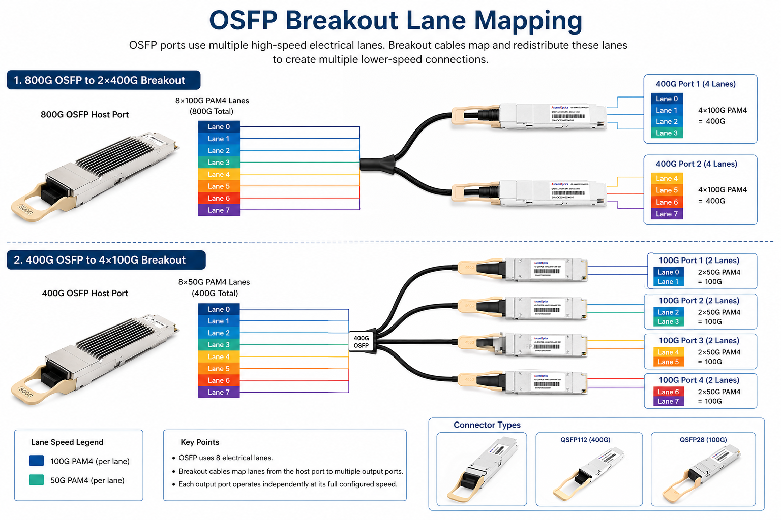
An OSFP breakout cable is a specialized cabling solution that divides a single high-speed OSFP port into multiple lower-speed connections. Unlike standard cables that maintain one-to-one port mapping, breakout cables enable one 800G port to simultaneously connect to two 400G endpoints, or one 400G port to connect to four 100G endpoints.
The technology works by redistributing electrical or optical lanes from the host port across multiple connector legs. An 800G OSFP interface typically uses eight 100G-class PAM4 electrical lanes (112G SerDes). A breakout cable maps four lanes to each 400G leg, creating two independent links that each operate at full 400 Gbps bandwidth.
This lane mapping happens internally within the cable assembly. For passive copper cables, direct traces handle the lane redistribution. For active cables, internal signal conditioning chips manage lane assignment while maintaining signal integrity. Network administrators can connect modern 800G switches directly to existing 400G equipment without external muxponders or protocol converters.
Need to understand standard OSFP connectivity first? Our complete 800G OSFP transceiver guide covers module types, form factors, and switch compatibility in detail.
OSFP Breakout Configurations
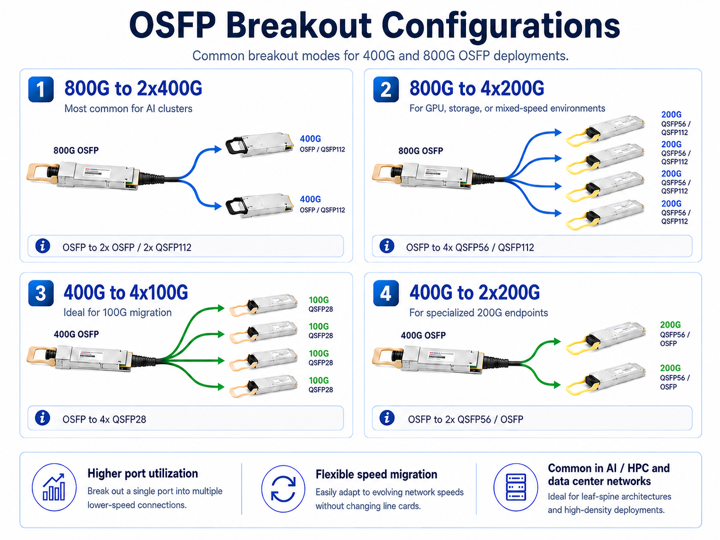
OSFP breakout cables support several configurations depending on the data rate of the host port and the speed requirements of the endpoint devices.
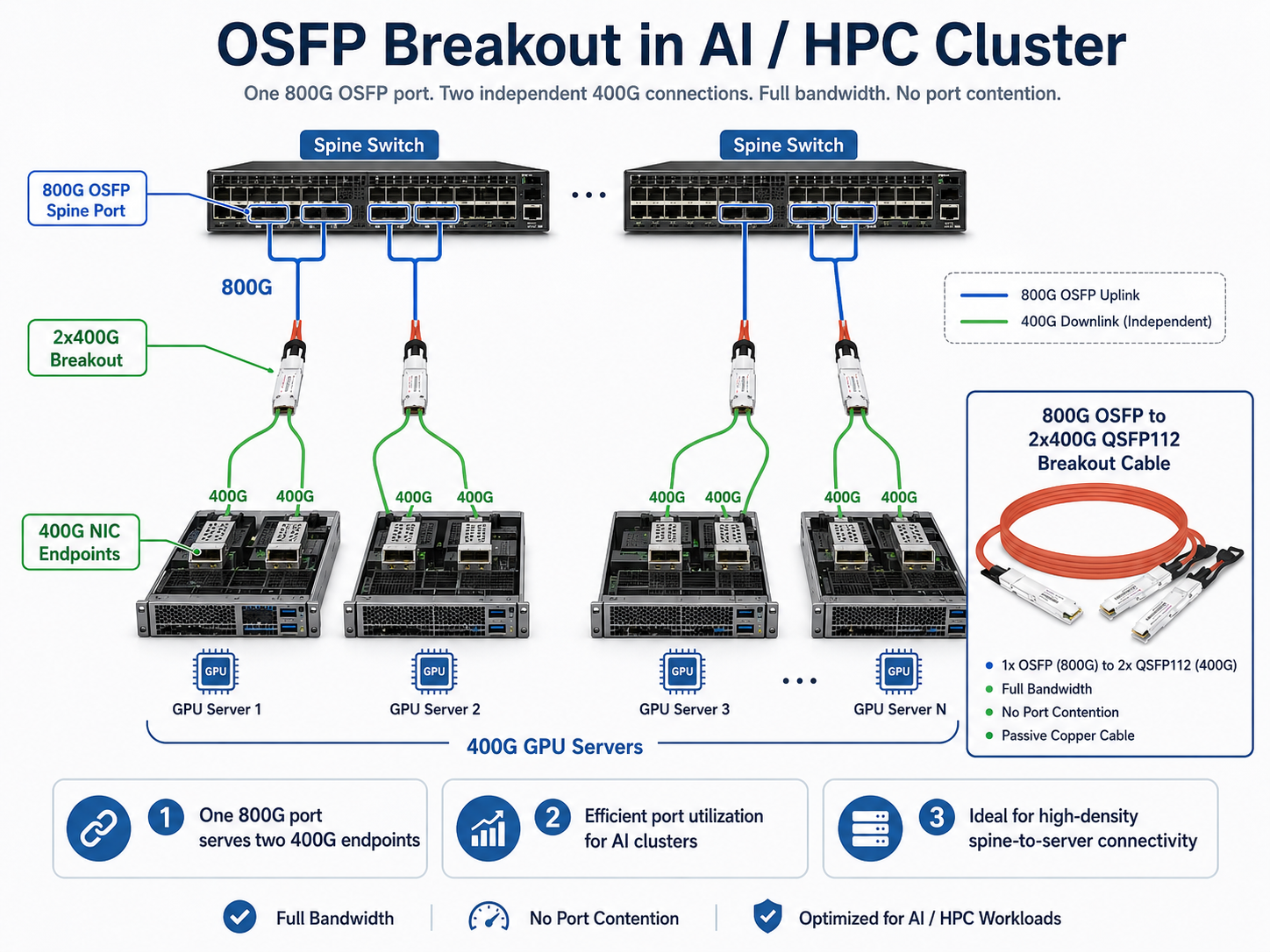
800G to 2x400G Breakout
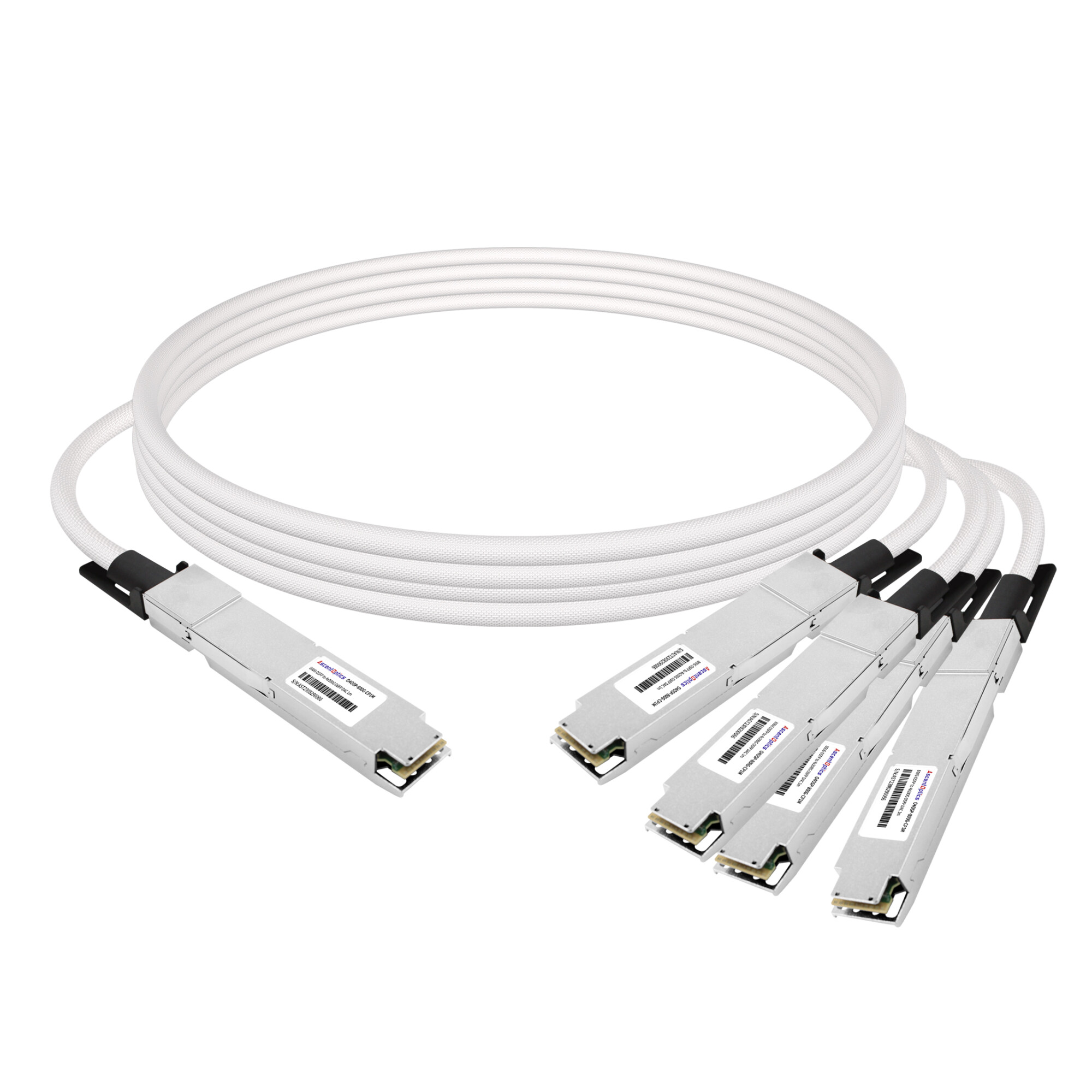
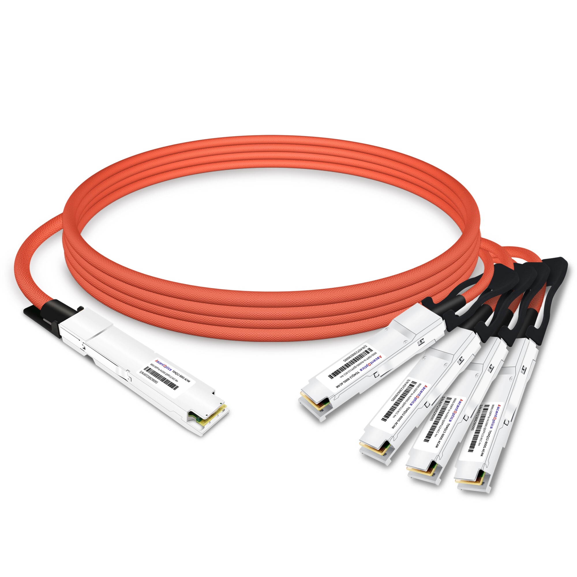
The 800G to 2x400G configuration is the most common OSFP breakout deployment in modern data centers. This configuration takes a single 800G OSFP port and splits it into two independent 400G connections.
Lane Mapping: The 800G host port provides eight 100G-PAM4 lanes. The breakout cable assigns lanes 0-3 to the first 400G leg and lanes 4-7 to the second 400G leg. Each leg operates as an independent 400G link with full bandwidth capability.
Connector Options:
- •OSFP to 2x OSFP: Both legs use OSFP connectors, ideal when connecting to servers or switches that also use OSFP ports
- •OSFP to 2x QSFP112: The host uses OSFP while the legs use QSFP112, common when connecting to NVIDIA ConnectX-7 or BlueField-3 adapters
Typical Applications:
- •Connecting 800G spine switches to dual 400G server NICs
- •Splitting 800G aggregation ports to serve two independent 400G leaf switches
- •Maximizing port efficiency in high-density AI training clusters
When Sarah Park’s team at a hyperscale AI provider deployed their first NVIDIA DGX H100 cluster, they faced exactly this challenge. Their Quantum-2 switches had 64 OSFP ports at 800G, but each DGX system needed two 400G connections for its InfiniBand adapters. Using 800G to 2x400G passive DAC breakout cables, they connected each switch port to two DGX nodes without consuming additional switch capacity. The breakout cables paid for themselves in the first month by eliminating the need for additional switch hardware.
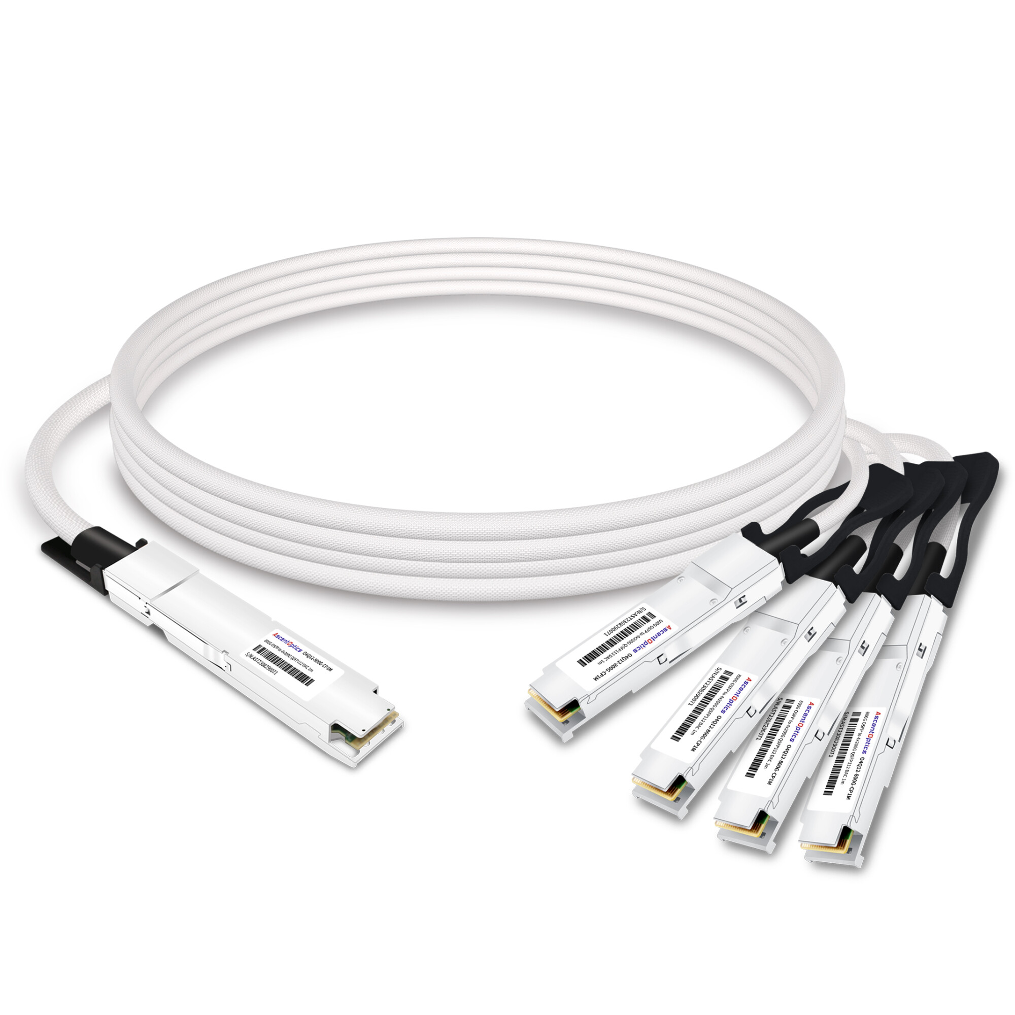
800G to 4x200G Breakout
The 800G to 4x200G configuration splits a single 800G port into four independent 200G connections. Each leg receives two 100G-PAM4 lanes, achieving 200 Gbps per connection.
Connector Options:
- •OSFP to 4x QSFP56: Connects to 200G endpoints using QSFP56 form factor
- •OSFP to 4x QSFP112: Connects to 200G endpoints using the newer QSFP112 form factor
Typical Applications:
- •GPU clusters where individual GPUs connect at 200G
- •High-density storage fabrics requiring many lower-speed connections
- •Test and development environments with mixed-speed equipment
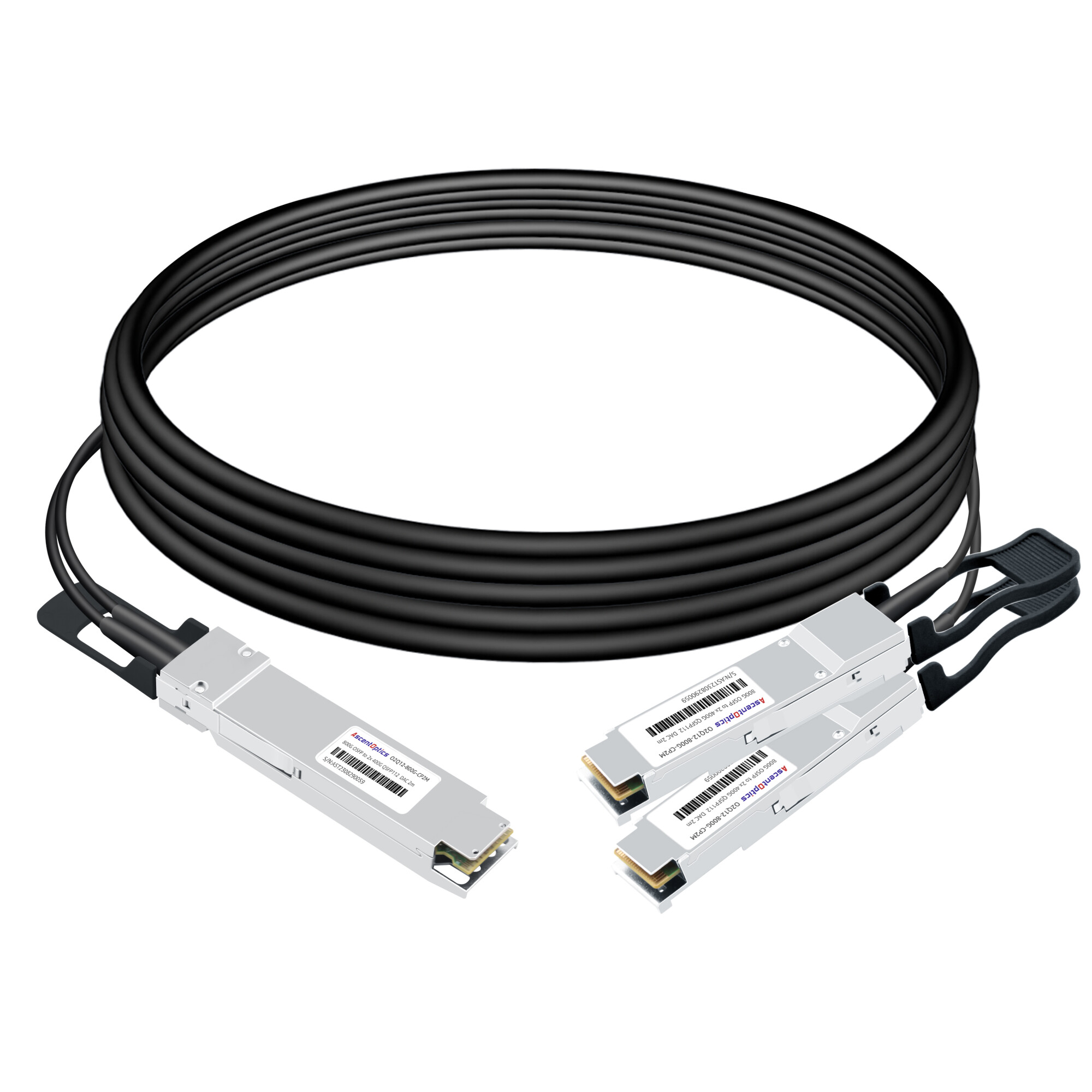
400G to 4x100G Breakout
The 400G to 4x100G breakout configuration is primarily used during infrastructure migration periods when organizations upgrade spine switches to 400G while maintaining existing 100G leaf and server equipment.
Lane Mapping: Depending on the module architecture, a 400G OSFP interface may use either 8×50G PAM4 lanes or 4×100G PAM4 lanes. In breakout scenarios targeting 4×100G, the host side commonly maps two 50G lanes to each 100G connection.
Connector Options:
- •OSFP to 4x QSFP28: The most common configuration for 100G endpoint connectivity
Typical Applications:
- •Spine-to-leaf connectivity during phased 100G to 400G upgrades
- •Connecting 400G aggregation switches to legacy 100G server NICs
- •Maximizing port utilization during transition periods
Want a detailed comparison with other breakout technologies? Our QSFP-DD breakout cable guide explains 400G to 100G breakout from the QSFP-DD perspective.
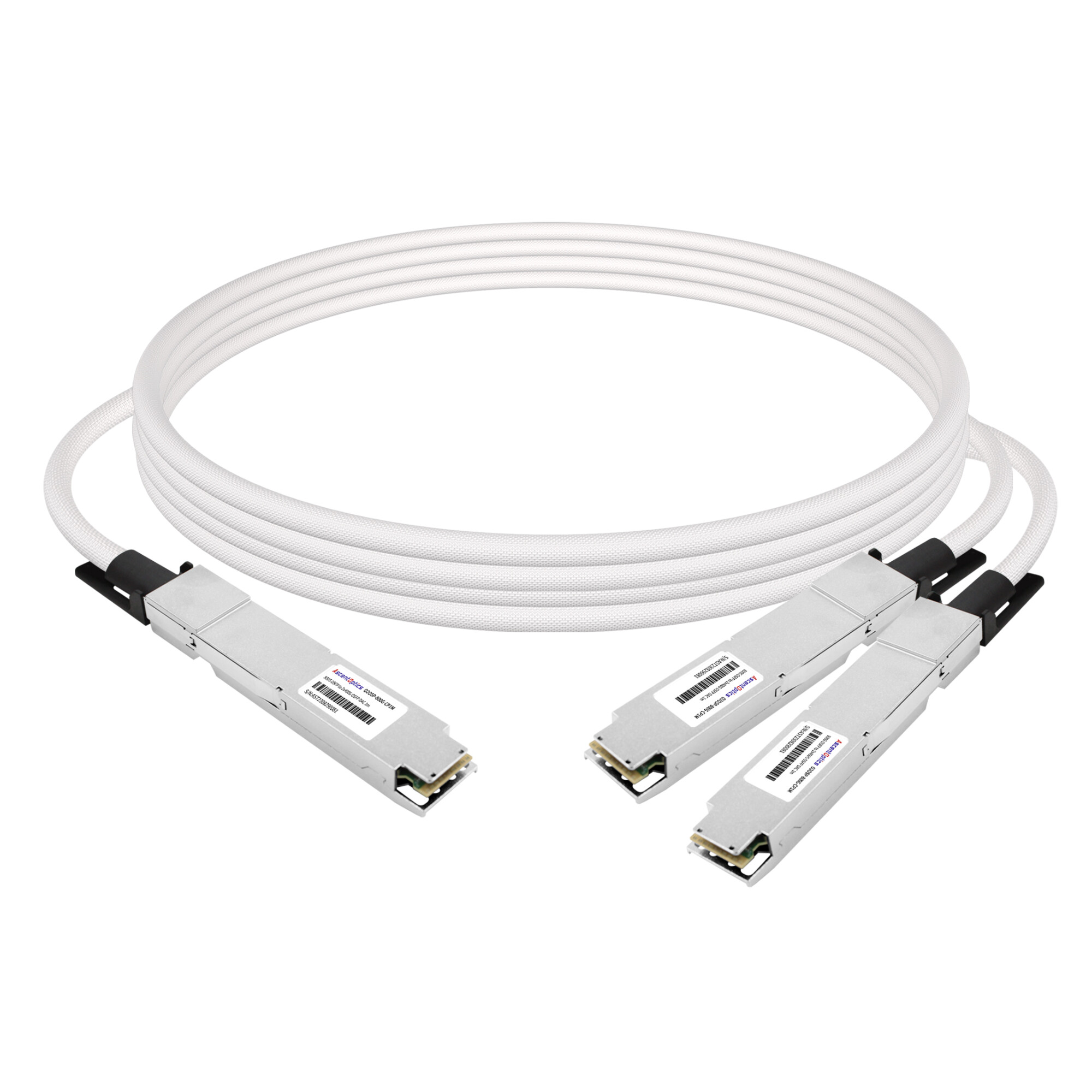
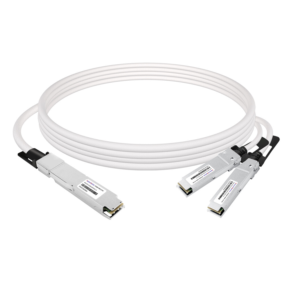
400G to 2x200G Breakout
The 400G to 2x200G configuration splits a single 400G OSFP port into two independent 200G connections. This is less common than the four-way split but useful when connecting to 200G endpoints such as storage controllers or specialized accelerators.
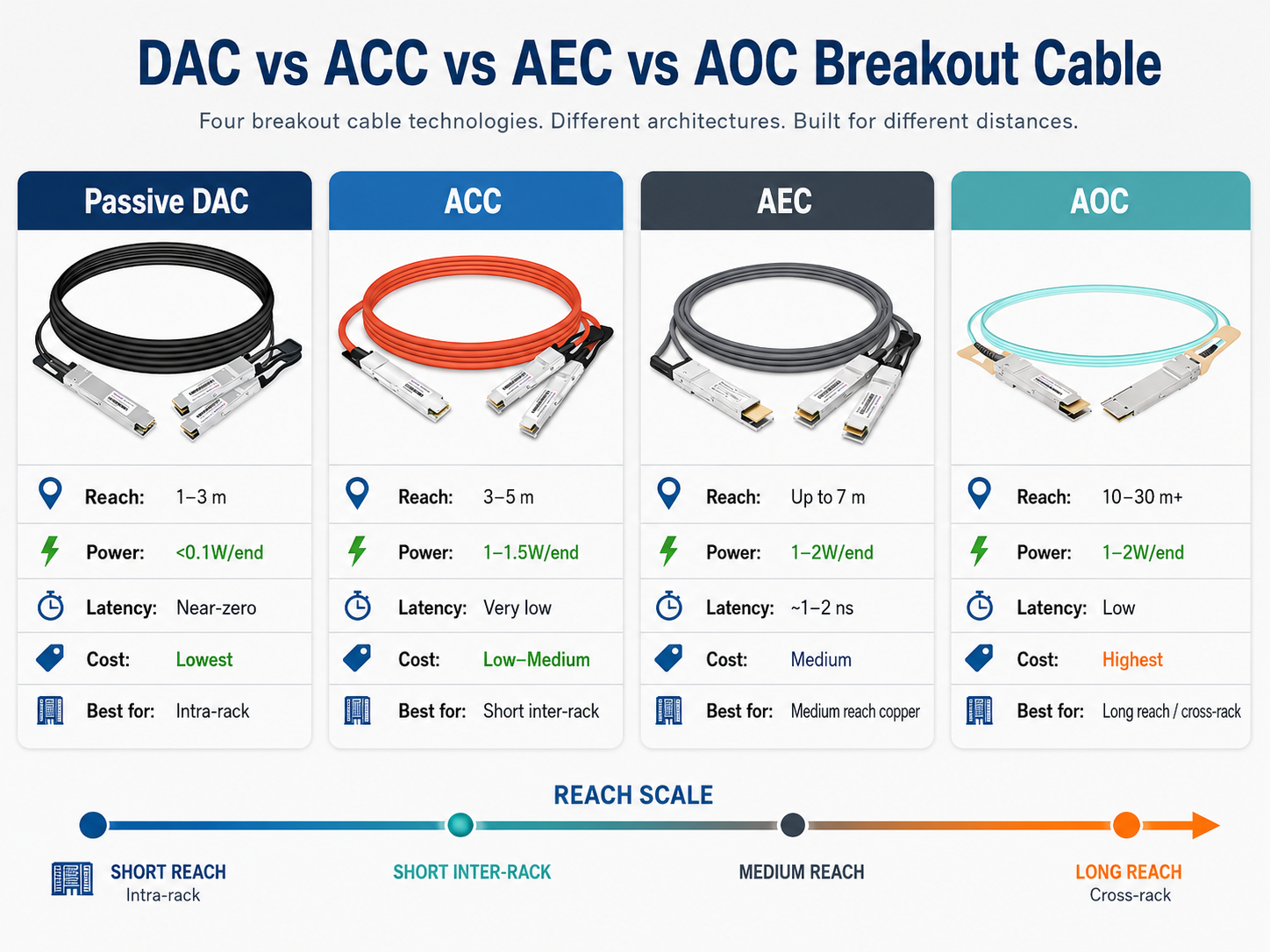
Breakout Cable Types: DAC, ACC, AEC, and AOC
OSFP breakout cables are available in four primary technologies, each offering different trade-offs between reach, power consumption, latency, and cost.
Passive Direct Attach Copper breakout cables are the simplest and most cost-effective option for OSFP breakout connectivity. They contain no active electronics. Lane mapping is handled through direct copper traces within the cable assembly.
| Specification |
Value |
| Maximum Reach |
1-3 meters (passive) |
| Power Consumption |
Less than 0.1W per end |
| Latency |
Near-zero (cable propagation only) |
| Cost |
Lowest |
| AWG Options |
28AWG (up to 2m), 26AWG (2.5-3m) |
Passive DAC breakout cables are ideal for intra-rack connections where the switch and endpoints reside in the same rack. The extremely low power consumption and near-zero latency make them the preferred choice for AI training clusters where every nanosecond of latency matters.
The primary limitation is reach. Signal integrity degrades rapidly in passive copper beyond beyond approximately 2–3 meters in most 800G deployments. Cable bend radius and installation stress also affect performance. For connections that span multiple racks or require routing through cable managers, active cable types are necessary.
Active Copper Cable breakout solutions add signal conditioning amplifiers to the cable assembly. These active components boost signal strength without full retiming, extending reach beyond passive DAC limitations while maintaining relatively low power consumption.
| Specification |
Value |
| Maximum Reach |
3-5 meters |
| Power Consumption |
Approximately 1-1.5W per end |
| Latency |
Low (minimal amplification delay) |
| Cost |
Low-Medium |
ACC breakout cables are well-suited for connections that need slightly more reach than passive DAC can provide. The additional power consumption is modest, and the cost premium over passive DAC is typically 20-30%. Many data centers use ACC breakouts for row-to-row connections within the same cold aisle.
Active Electrical Cable breakout solutions incorporate retimer chips that fully reshape and reclock the PAM4 signals. This provides the best signal integrity of any copper-based solution and enables the longest copper reaches. Terminology may vary slightly between vendors, especially for ACC and AEC classifications.
| Specification |
Value |
| Maximum Reach |
Up to 7 meters |
| Power Consumption |
Typically 1–2W per end depending on cable length and retimer design. |
| Latency |
Low (~1-2 ns added) |
| Cost |
Medium |
AEC breakout cables represent a middle ground that is increasingly popular for 400G and 800G deployments. The in-cable retimers compensate for signal degradation, enabling reliable operation at distances where passive DAC fails and ACC struggles. The power consumption is higher than passive DAC but lower than AOC solutions.
For 400G to 4x100G breakout configurations, AEC is often the only viable option when the cable run exceeds 3 meters. The retimer technology handles the complex lane mapping and signal conditioning required for reliable four-way splits over longer distances.
Active Optical Cable breakout solutions convert electrical signals to optical signals at the host connector, transmit over fiber, and convert back to electrical at each leg connector. This provides the longest reach and best signal integrity of all breakout cable types.
| Specification |
Value |
| Maximum Reach |
10-30 meters (up to 100m for some variants) |
| Power Consumption |
1-2W per end |
| Latency |
Low (typically below 100 ns) |
| Cost |
Highest |
| Fiber Type |
Multimode OM3/OM4 or single-mode |
AOC breakout cables are the right choice for cross-rack, row-to-row, or inter-cluster connections. The optical transmission is immune to electromagnetic interference and provides consistent performance regardless of cable routing. The lightweight fiber is also easier to manage in high-density environments compared to thick copper twinax.
The trade-off is cost. AOC breakout cables typically cost 3-5x more than equivalent passive DAC solutions. Power consumption is also higher due to the optical transceivers embedded in each connector.
Breakout Cable Type Comparison
| Feature |
Passive DAC |
ACC |
AEC |
AOC |
| Reach |
1-3m |
3-5m |
Up to 7m |
10-30m+ |
| Power |
Less than 0.1W |
1-1.5W |
~1W |
1-2W |
| Latency |
Near-zero |
Very low |
Low |
Low |
| Cost |
Lowest |
Low |
Medium |
Highest |
| Best For |
Intra-rack |
Short inter-rack |
Medium reach |
Long reach |
Form Factor Considerations
OSFP breakout cables involve multiple connector form factors on the same cable assembly. Understanding these form factors ensures compatibility between the host switch and endpoint devices.
Finned Top vs Flat Top
The 800G or 400G host end of a breakout cable typically uses a finned top OSFP connector. The integrated heatsink fins improve thermal dissipation when the connector is installed in a switch cage with restricted airflow.
The 400G or 200G leg connectors may use either flat top (RHS) or finned top depending on the endpoint device:
- •Flat top OSFP: Used on NICs and adapters that have their own riding heatsinks or operate in environments with better airflow
- •Finned top OSFP: Used when the endpoint also requires enhanced thermal management
Always verify the form factor requirements of both the host switch and endpoint devices before ordering breakout cables. Installing a finned top connector in a cage designed for flat top can damage the connector or prevent proper seating.
OSFP vs QSFP112 Legs
When the host port uses OSFP and the endpoints use a different form factor, breakout cables bridge the physical gap:
- •OSFP to OSFP legs: Used when both host and endpoints support OSFP. This is the simplest configuration and offers the most straightforward compatibility.
- •OSFP to QSFP112 legs: Used when connecting to 400G endpoints that use the QSFP112 form factor. QSFP112 is backward compatible with QSFP56 and QSFP28, providing a migration path for mixed-speed environments.
Looking for compatible switch options? Our OSFP-compatible switches guide lists platforms from NVIDIA, Cisco, Arista, and Juniper that support breakout configurations.
OSFP Breakout Applications
AI and HPC Clusters
AI training clusters represent the fastest-growing application for OSFP breakout cables. NVIDIA Quantum-2 InfiniBand switches and Spectrum-4 Ethernet switches use 800G OSFP ports that commonly need to fan out to ConnectX-7 adapters.
In a typical deployment, each Quantum-2 switch port connects via an 800G to 2x400G breakout cable to two DGX H100 or GB200 systems. This maximizes the expensive switch port utilization while providing each GPU node with the full 400G bandwidth it requires.
The ultra-low latency of passive DAC breakout cables is particularly important here. AI training workloads are highly sensitive to inter-GPU communication latency, and the nanoseconds saved by using passive copper instead of active optical solutions can translate to meaningful training time reductions at scale.
Data Center Migration
OSFP breakout cables provide a cost-effective bridge strategy for data centers upgrading from 100G or 400G to 800G infrastructure. Rather than replacing every endpoint simultaneously, network architects can:
- 1. Upgrade spine switches to 800G OSFP ports
- 2. Use breakout cables to maintain connectivity to existing 400G or 100G leaf switches
- 3. Replace leaf switches to native 800G on a separate schedule
- 4. Eventually remove breakout cables as the infrastructure converges to native speeds
This phased approach typically reduces migration capital expenditure by 60-80% compared to full infrastructure replacement.
Spine-Leaf Architectures
In spine-leaf networks, breakout cables optimize port density at the spine layer. A 64-port 800G spine switch using 800G to 2x400G breakout cables effectively provides 128 400G downstream connections. This doubles the leaf switch attachment capacity without requiring additional spine hardware.
For cloud providers operating multi-tenant environments, this port multiplication is essential. Each spine port can serve two independent tenants or availability zones without bandwidth contention.
Compatibility and Deployment Considerations
Switch Compatibility
Not all switches support breakout operation, and support varies by platform and software version. Before deploying OSFP breakout cables, verify that your switch supports the specific breakout configuration you need.
Key considerations:
- •Port-level breakout enablement: Some switches require explicit configuration to enable breakout mode on a per-port basis.
- •CMIS management: The switch must support CMIS 5.0 or later to properly manage multi-lane breakout configurations. Breakout operation is typically managed through CMIS-based lane control, allowing the switch ASIC to treat a single physical port as multiple logical interfaces.
- •Protocol compatibility: Verify that the breakout configuration supports your required protocol (Ethernet, InfiniBand, or both).
Protocol Support
Most passive OSFP breakout DAC cables are protocol-agnostic. The cable simply redistributes electrical lanes without interpreting the protocol. This means the same breakout cable can carry Ethernet, InfiniBand, or Fibre Channel traffic depending on the switch and endpoint configuration.
Active breakout cables (ACC, AEC, AOC) may have protocol-specific firmware. Always verify protocol compatibility with the cable vendor, especially for InfiniBand deployments where signal timing requirements are stricter than Ethernet.
Length and Distance Planning
Accurate cable length planning prevents costly rework. When measuring for breakout cables:
- 1. Measure the physical path from host port to each endpoint port
- 2. Add 0.5 meters for cable management and strain relief
- 3. Add 0.3 meters for each 90-degree bend in the cable path
- 4. Select the next standard cable length (1m, 1.5m, 2m, 2.5m, 3m)
Remember that passive DAC performance degrades with length. For runs approaching 3 meters, consider upgrading to ACC or AEC to ensure signal integrity margins.
Planning a cable deployment? Our engineers can help you select the right breakout configurations for your specific switch and NIC combination. Contact our optical networking team for a compatibility assessment.
Conclusion
OSFP breakout cables solve one of the most expensive challenges in modern data center networking: how to connect new high-speed switches to existing lower-speed endpoints without a full infrastructure replacement. A single passive DAC breakout cable costing under $200 can replace thousands of dollars in switch ports and endpoint hardware while maintaining full bandwidth on every connection.
Key takeaways for network architects:
- •The 800G to 2x400G breakout configuration is the most common deployment for AI clusters and high-density switching
- •Passive DAC breakout cables offer the lowest cost, lowest latency, and lowest power for intra-rack connections under 3 meters
- •AEC breakout cables provide the best reach-to-cost ratio for copper connections up to 7 meters
- •AOC breakout cables are the right choice for cross-rack and long-distance connections
- •Always verify switch breakout support and endpoint form factor compatibility before ordering
- •Breakout cables can reduce migration costs by 60-80% compared to full endpoint replacement
Selecting the right OSFP breakout cable requires matching the cable type to your reach requirements, the leg configuration to your endpoint form factors, and the protocol support to your network stack. Understanding these variables ensures a deployment that meets both current needs and future growth.
Future 1.6T systems may evolve toward OSFP-XD and next-generation 224G SerDes architectures, but current breakout strategies remain centered around standard OSFP 800G deployments.
Ascent Optics provides a comprehensive range of OSFP breakout cables including 800G to 2x400G passive DAC, ACC, and AEC variants. Our engineering team helps customers select the optimal breakout configuration based on switch platform, endpoint type, and distance requirements. Request a quote for your next breakout cable deployment.
Frequently Asked Questions About OSFP Breakout Cables
Q1: What is the maximum reach of an OSFP breakout cable?
Reach depends on the cable type. Passive DAC breakout cables support up to 3 meters. ACC breakout cables extend this to 5 meters. AEC breakout cables reach up to 7 meters. AOC breakout cables can span 10-30 meters or more depending on the fiber type.
Q2: Can both breakout ports operate at full speed simultaneously?
Yes. In an 800G to 2x400G breakout configuration, both 400G legs operate as independent links with full 400 Gbps bandwidth. There is no bandwidth sharing or contention between the split ports.
Q3: Does a breakout cable add latency?
Passive DAC breakout cables add negligible latency. ACC and AEC cables add minimal latency from signal conditioning (typically less than 2 nanoseconds). AOC cables add approximately 0.1 microseconds from the electrical-to-optical conversion. For most data center applications, these latencies are insignificant.
Q4: Is OSFP backward compatible with QSFP28 or QSFP56?
No. OSFP is not mechanically backward compatible with QSFP28 or QSFP56 interfaces without an adapter or breakout solution. This is why breakout cables are essential. An OSFP to 4x QSFP28 breakout cable bridges the physical and electrical gap between a 400G OSFP host port and 100G QSFP28 endpoints.
Q5: Can I use an OSFP breakout cable with any 800G switch?
Not all 800G switches support breakout operation. The switch must explicitly support port splitting in its hardware and firmware. Common platforms with breakout support include NVIDIA Quantum-2, Spectrum-4, and select models from Cisco, Arista, and Juniper. Verify compatibility with your switch vendor before purchasing breakout cables.
Q6: What is the difference between ACC and AEC breakout cables?
ACC (Active Copper Cable) uses signal amplifiers to boost signal strength without full retiming. AEC (Active Electrical Cable) incorporates retimer chips that reshape and reclock the PAM4 signals. AEC provides better signal integrity and longer reach than ACC but at a slightly higher cost.
Q7: Should I choose OSFP or QSFP112 legs for my breakout cable?
Choose OSFP legs when both the host switch and endpoint devices use OSFP ports. Choose QSFP112 legs when connecting to endpoints such as ConnectX-7 adapters that use the QSFP112 form factor. QSFP112 offers backward compatibility with QSFP56 and QSFP28, which can be valuable in mixed-speed environments.
OSFP MSA
NVIDIA Networking
Post Views: 1,327